
Influence of High Viscosity and Magnetoviscous Effect on the Washout Resistance of Magnetic Fluid
1
State Key Laboratory of Tribology, Department of Mechanical Engineering, Tsinghua University, Beijing 100084, China
2
College of Mechanic and Electronic Engineering, Beijing University of Chemical Technology, No. 15 North Third Ring East Road, Beijing 100013, China
*
Author to whom correspondence should be addressed.
Magnetochemistry 2023, 9(5), 134; https://doi.org/10.3390/magnetochemistry9050134
Submission received: 11 April 2023
/
Revised: 16 May 2023
/
Accepted: 16 May 2023
/
Published: 19 May 2023
(This article belongs to the Special Issue Advanced Applications of Magnetic Field-Responsive Fluid)
Abstract
:Magnetic fluid seals have long been thought to be a successful sealing form while sealing liquids are always a challenge. The instability of the liquid–liquid interface under the washout has become the key technical problem that hinders the realization of sealing liquid. This work mainly presents an experimental study about the influence of high viscosity and magnetoviscous effects on washout resistance. Three engine oil-based magnetic fluids of different viscosities were prepared with two kinds of surfactants. The magnetoviscous effects of the prepared magnetic fluids under different working conditions were found through rheological experiments. The viscosity of the three samples decreased at most by about 100 times with the shear rate increasing. An experimental platform was designed and built for the washout tests. The entire process of magnetic fluids being washed away was obtained experimentally. The magnetic fluid of higher viscosity can remain stationary with lower magnetic force. The quantitative results show that the viscosity of the magnetic fluid has a significant influence on washout resistance under a magnetic field.
1. Introduction
As a new type of functional material, magnetic fluid has unique properties with both superparamagnetism and fluidity [1,2], which can be controlled by the action of an external magnetic field [3,4]. The magnetic fluid sealing technology is an excellent sealing technique and has been mature for gas sealing, but it is still in the early stage of sealing water [5].
In previous studies, specific structures of magnetic fluid seals have been designed to improve the seal capacity in a water environment. Szydlo and Matuszewski [5] and Szydlo and Szczech [6] conducted a series of studies on magnetic fluid seals for water sealing applied to the main shaft of a ship spiral propeller. In short sealing experiments, it was found that the magnetic fluid sealing device with a retaining ring could increase the critical boundary speed of leakage from 10.47 m/s to 14.14 m/s. They also separately conducted single-stage and three-stage seal experiments and found that the viscosity has a significant influence on sealing life [7]. However, they did not make a more detailed analysis.
Miitamura [8,9] carried out a series of magnetic fluid sealing experiments with water in order to study the rotating shaft sealing problem of blood pumps and found that reducing the contact area between the magnetic fluid and the sealed medium can significantly improve the sealing life of the magnetic fluid seal. Young Sam Kim prepared a new kind of magnetic fluid and improved the properties of magnetic fluid in sealing diesel engine (lubricating) oil. Kim [10] and Kurfess and Mauller [11] completed a series of experimental studies on magnetic fluid sealing for liquid media and concluded that the magnetic field gradient, magnetic fluid viscosity, rotational speed and other factors have an important influence on the serve life. Marcin Szczech [12] carried out a sealing test by using ferrofluids (FFs) resistant to water in which the shaft rotated over 4.3 million times without failure and provided recommendations for the selection of magnetic fluid, sealing stage width and FF volume.
Many scholars focus on the interfacial instability. Singh [13] studied the ferrofluid–mercury interface under a nonuniform magnetic field and noted the instability growth to be monotonic under the field gradient. Kögel [14] and Völkel [15] experimentally studied the effect of horizontal magnetic field on the interfacial instability of magnetic fluid. The critical flow velocity under different driving frequencies and an external magnetic field can be determined according to the growth rate and decay rate of interface fluctuation. Cui [16] studied the effect of gravity and shear flow on adhesion of magnetic fluid and found that the enhancement of a vertical magnetic field could improve the critical magnetic Bond number and reduce the critical Weber number, which makes the magnetic droplet more susceptible to shear flow. Bohlius [17] deduced the dispersion relationship of interfacial waves in magnetic films under a vertical magnetic field. The influence of surface elasticity, surface magnetism and anisotropic magnetic films on the instability of solid iron gel films under magnetic field was studied. Li [18] studied the flow field of the liquid interface layer of magnetic fluid seal by simulation and optimized the method to decrease the maximum turbulence intensity by more than 20% compared to that in the traditional structure. Nevertheless, most of the studies about interfacial instability of magnetic fluids are theoretical.
In this study, we aimed to explore the influence of FF viscosity and magnetoviscous effect on the washout resistance to water. Three kinds of magnetic fluids were prepared by using engine oils with different viscosities with a coprecipitation method. The magnetoviscous effects of the prepared magnetic fluids under different working conditions were found through rheological experiments. With a high-definition video equipment and measuring system, we analyzed the phases of magnetic fluid washout and demonstrated the significant effect of viscosity on washout resistance.
2. Materials and Method
2.1. Materials
Three engine oil-based magnetic fluids were prepared with carrier fluids of different viscosities. The order of the molecular weights of each sample is: sample 1 < sample 2 < sample 3. The Fe3O4 nanoparticles were synthesized by coprecipitation without protective gas in air. The particles coated with the surfactant were dispersed in different types of engine oil by stirring. Polyisobutylene succinimide (OLOA) and cido erucico were used as surfactants to steadily disperse nanoparticles. The three kinds of carrier fluids belong to total loss system oil, so their components and structures are similar, and they also possess similar densities and surface tension values. The quality of Fe3O4 nanoparticles was controlled and the difference in saturation magnetization of magnetic fluids was no more than 20%. The size of the magnet was 15 mm × 10 mm × 5 mm and the direction of magnetization was along the shortest side. The type and material were, respectively, N35 and NdFeB.
2.2. Viscosity Measurement
In this study, we chose an advanced commercial rheometer with an electromagnetic module to measure ordinary viscosity under the magnetic field, as well as viscosity under the magnetic field of sufficient field intensity and variation in a wide range of shear rates.
Experiments were carried out under a rotational rheometer in combination with a commercial magnetorheological device (MRD) cell manufactured by Anton Paar, using a plate geometry rotor (model: PP20) with a diameter of 19.940 mm. The gap between the plate rotor and the bottom plate was set to 0.2 mm and the volume of magnetic fluid used in tests was 0.1 mL. A homogenous field and perpendicular field lines with respect to the bottom plate were guaranteed by the plate covered by a magnetic yoke. The MRD was fully integrated into the measurement and control system, controlling the magnetic field and recording all important parameters.
2.3. Washout Test and Experimental Platform
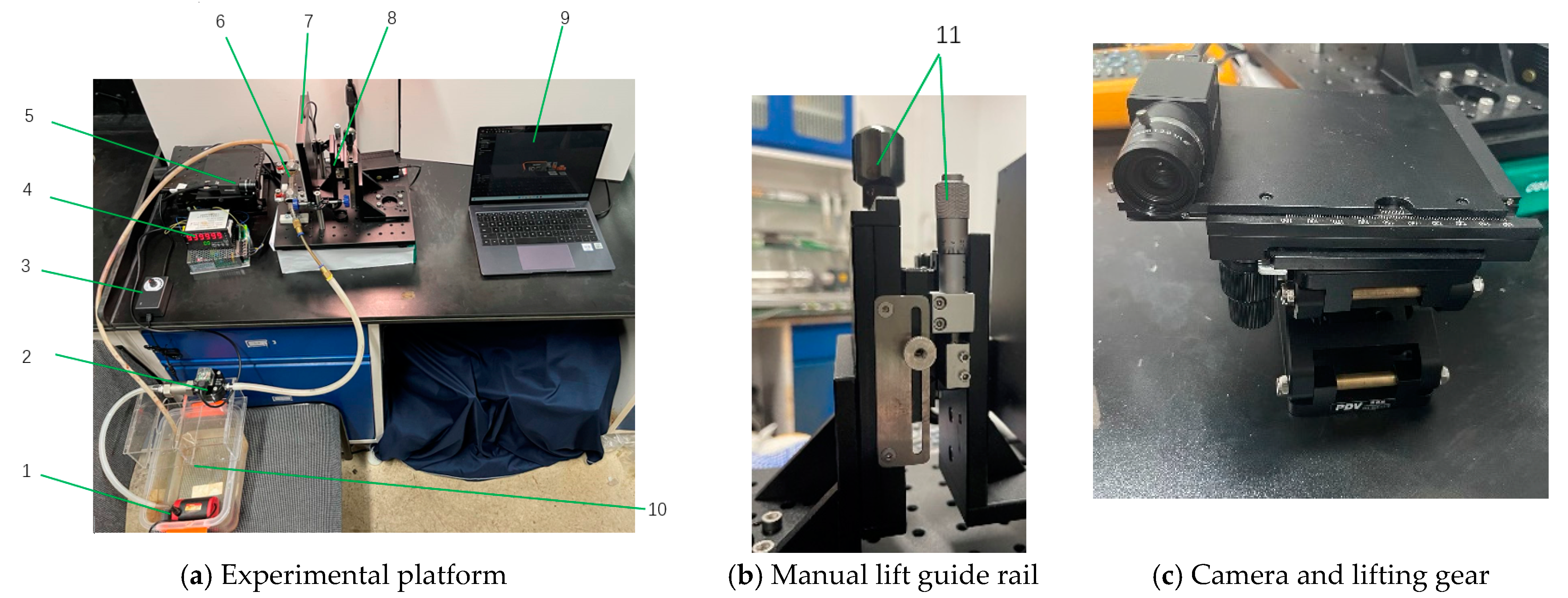
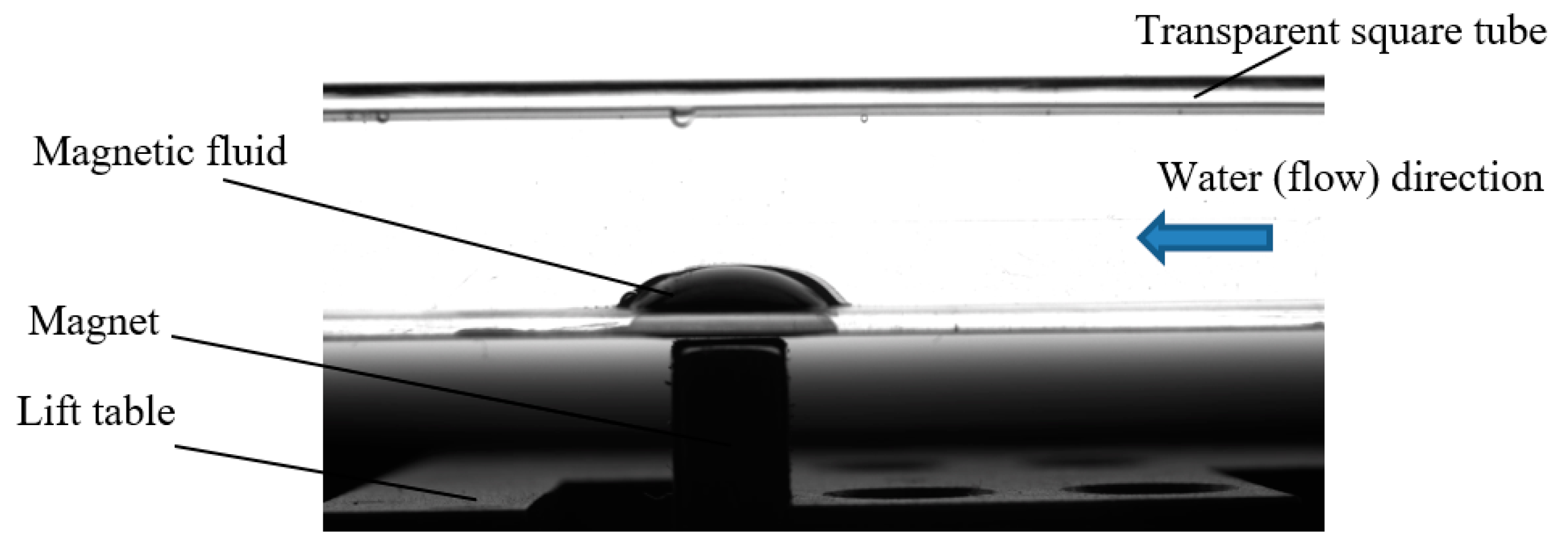
An experimental platform was designed and built to meet the requirements in this study. A general view of the experiment platform is shown in Figure 2. The magnet is fixed on the lift table. The lift table can be adjusted by the knob with accuracy of 0.01 mm. The max pump flow reaches 3000 mL/min and the flow velocity can be adjusted by a pump flow regulator. The flow velocity in the tube can be measured by a flow meter in the measurement range 100~10,000 mL/min, with an accuracy within 0.1% of the maximum range. The images of magnetic fluid can be visualized by a black and white camera (FA1610C from Kmoma Vision Company, Seoul, Republic of Korea) with a 16mm prime lens and transferred to the computer. Figure 3 shows the photograph of washout progress captured on camera.
A transparent square tube of PMMA was used as a fluid-flow pathway. Magnetic fluid was injected into the middle of the tube just above the rectangular magnet, using a syringe with a long needle. The injection volume of magnetic fluid was same in each set of trials.
2.4. Theory and Calculation
2.4.1. Ferrohydrodynamic Analysis of the Washout
Based on ferrohydrodynamic analysis (Rosensweig [17]), the magnetic force applied to magnetic fluid can be theoretically calculated in gaseous or liquid environments. As proposed by Rosensweig [17], the Bernoulli equation of ferrofluid dynamics under steady or time-varying magnetic fields is:
where p is the total pressure in the fluid, v is the velocity of the fluid, is the fluid density, g is the gravitational acceleration, h is the height of the fluid, M is the modules of magnetization, H is the magnetic field intensity, is the permeability of vacuum, M is the magnetization of the magnetic fluid.
The critical pressure value is determined by the difference between the maximum and the minimum magnetic field intensity. From the Bernoulli equation [19] applied on the magnetic fluid in the magnetic field, the total force density of the magnetic fluid can be approximately expressed as:
where Hmax and Hmin are the maximum and minimum magnetic field intensities on the horizontal line of half the height of the magnetic droplet; Bmax and Bmin are the maximum and minimum magnetic flux densities on the horizontal line of half the height of the magnetic droplet.
2.4.2. Mechanism of Magnetic Fluid Washout
There are two different methods of magnetic fluid washout, and their mechanisms are completely different. One involves washing away owing to the increasing water velocity. The other is washout at a fixed water velocity after working for a period, which is defined as wastage. The mechanism of magnetic fluid washout is not fully understood. Mitamura [20] believes that Kelvin–Helmholtz instability is a main reason for washout and causes the failure of magnetic fluid seals. Rosensweig [11] produced a criterion for instability in the magnetic Kelvin–Helmholtz problem with the following model:
where fluid a is a nonmagnetic fluid and fluid b is a magnetic fluid; Ua and Ub are the fluid velocities; and are the densities; and are the relative permeabilities of fluid a and b; is the interfacial surface tension; g is the gravity constant; and Hy is the applied magnetic field intensity parallel to the unperturbed surface.
As shown in Equation (3), the larger the applied field and the larger the difference in permeability across the interface, the greater the velocity contrast that can be withstood before destabilization. However, the model of Kelvin–Helmholtz instability neglects the influence of viscosity and assumes that both fluids are inviscid.
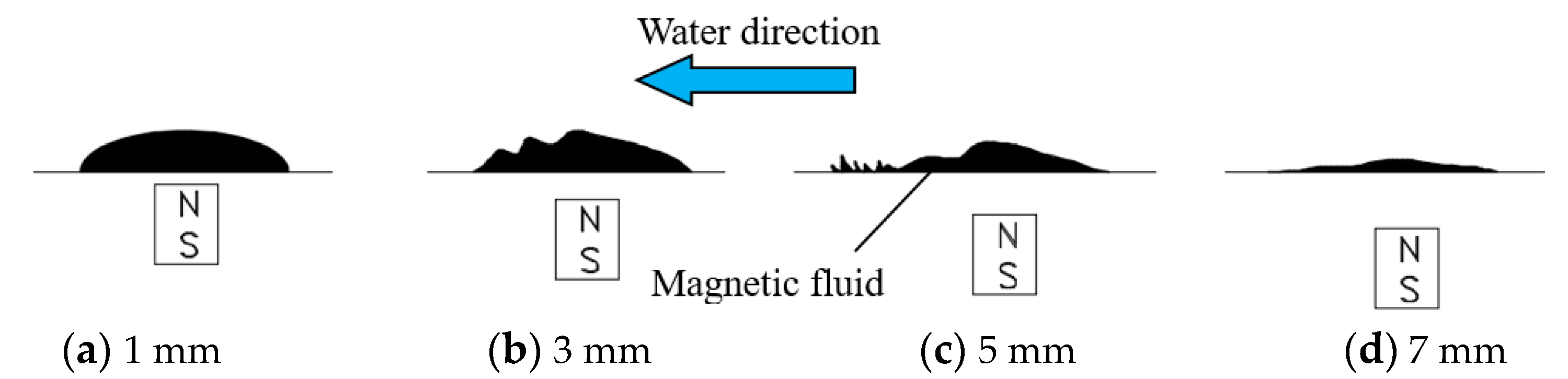
The process of magnetic fluid washout is shown in Figure 4 and the velocity of the water is constant. Figure 4a,b,c,d, respectively, demonstrate the magnetic droplet states with different distances between magnet and magnetic fluid. As the distance between magnet and magnetic fluid increases, the surface of the magnetic droplet starts to show unstable ripples and the fluctuation frequency increases. Finally, the droplet achieves balance under the magnetic force generated from the nonuniform magnetic field. When the magnetic force descends to a certain degree, the magnetic fluid starts being washed away. Once the process of washing away starts, it will not stop until the magnetic fluid reduces to a certain volume.
2.4.3. Chain Model of Magnetoviscous Effect
Under the influence of strong magnetic fields, magnetic particles can aggregate to form different shapes of microstructure, such as chain and droplet structures, which leads to significant changes in the viscosity of magnetic fluid [18]. This phenomenon is normally referred to as the magnetoviscosity effect. Under a certain magnetic field intensity, with the increase in shear rate, the viscosity of magnetic fluid decreases and the microstructure breaks. The chain model gives a reasonable explanation for the magnetoviscous effect, in which the magnetic interactions between particles must be strong enough to hold the chains together [21].
Odenbach [22] described magnetic fluid as a double dispersion system containing a large number of small particles and a small number of large particles. Under the assumption that the chain is rigid and straight, they formulated a chain model and calculated free energy in the following form:
where gn represents the chain length distribution function, mchain is the magnetic moment of a particular chain interacting with the field, k is the Boltzmann constant, T is the absolute temperature, represents the permeability of vacuum. The first term in the bracket in Equation (4) is the free energy of the ideal gas and the second term accounts for the interaction with the field. Hence, the maximum length of a chain can be treated as a function of shear rate, and the maximum number of particles in a chain can be calculated in the following equation [19]:
where is the viscosity of the zero magnetic field, represents the permeability of vacuum, M0 represents the spontaneous magnetization of the magnetic fluid, is the shear rate, d is the mean diameter of magnetic particles and is the surfactant layer thickness.
3. Results and Discussion
3.1. Magnetoviscous Property of Magnetic Fluids
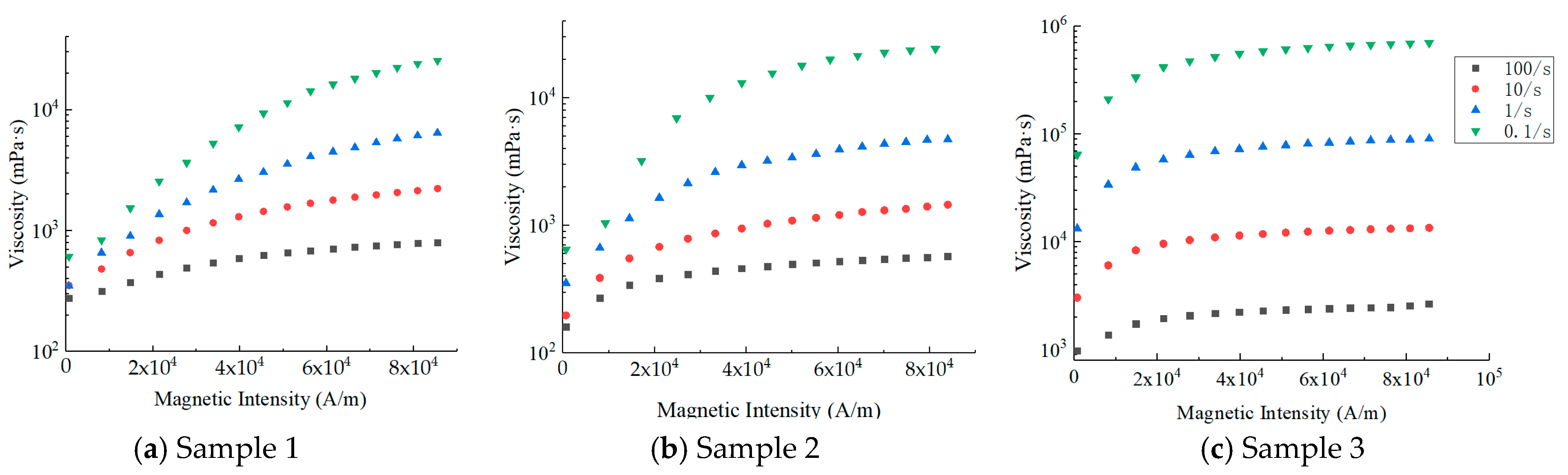
The relationships of viscosity and magnetic induction intensity of three magnetic fluids are shown in Figure 5. The temperature is maintained at 20 °C, the magnetic intensity is in the range of 0~90,000 A/m and the shear rates are set to 0.1/s, 1/s, 10/s, 100/s, respectively. In Figure 5, we can see that the viscosity increased 3~38 times due to the applied field, revealing the significant magnetoviscous effect.
When the system is in the flow state, the conformation of the macromolecular chain is forced to change due to the external force. When the shear rate is small, the conformational change speed of the molecular chain is decelerated by the magnetic field, which contributes to high viscosity macroscopically. In systems with high shear rates, the conformation of the polymer chain changes obviously and the orientation of large polymer chains is along the flow, which leads to a slow growth of viscosity as the magnetic field strength increases.
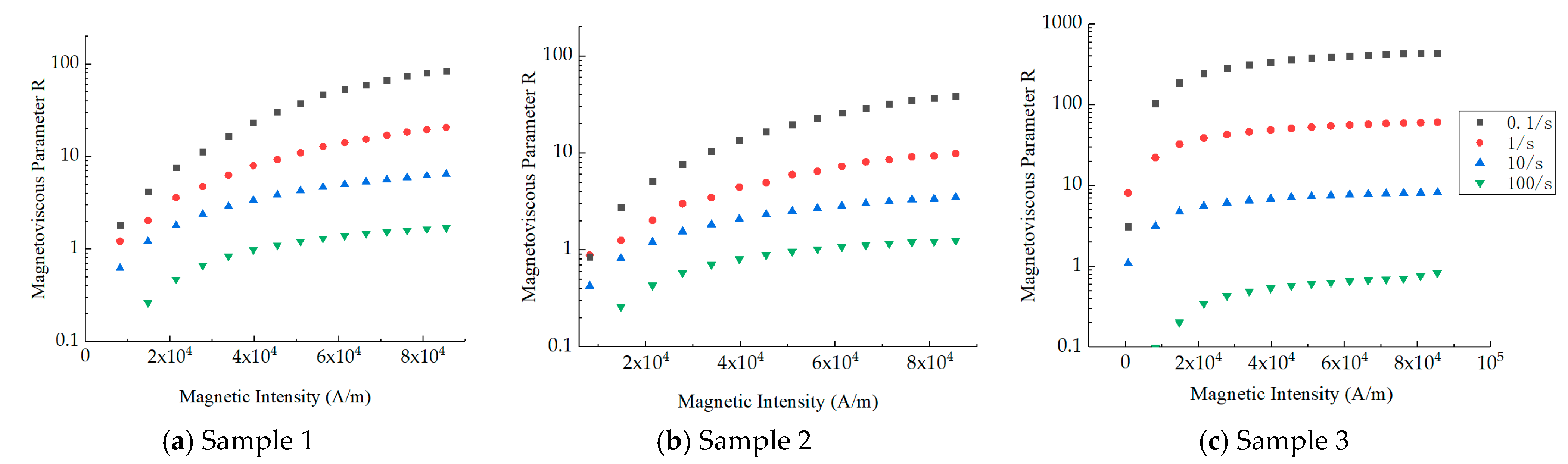
The extent of the magnetoviscous effect is usually quantified by the magnetoviscous parameter R [19]:
where and are the viscosities of the magnetic fluid at zero field and an applied field, respectively.
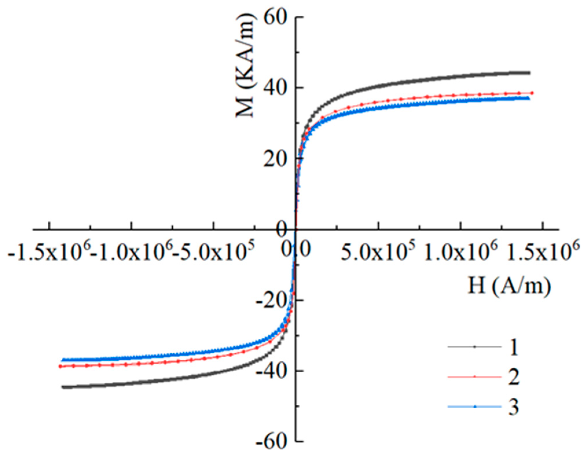
As shown in Figure 6, the magnetic field has an important influence on the viscosity of the three samples, especially under the condition of low shear rate. When the shear rate is 0.1/s and the magnetic intensity is over 40,000 A/m, the magnetoviscous parameters of samples are all above 10. While the shear rate is 100/s, the magnetoviscous parameters of the three samples are all below 2. From Equation (5), we can determine that the maximum number of particles in a chain nmax increases with a decrease in shear rate , which contributes to the rise of the viscosity at an applied field . Due to the high saturation magnetization and magnetization tendency shown in Figure 1 and the relationship between M0 and nmax, the M0 increases obviously with the magnetic intensity before 40,000 A/m so that has a rapid growth. It is concluded that the three samples of magnetic fluid have a strong magnetoviscous effect under a low shear rate.
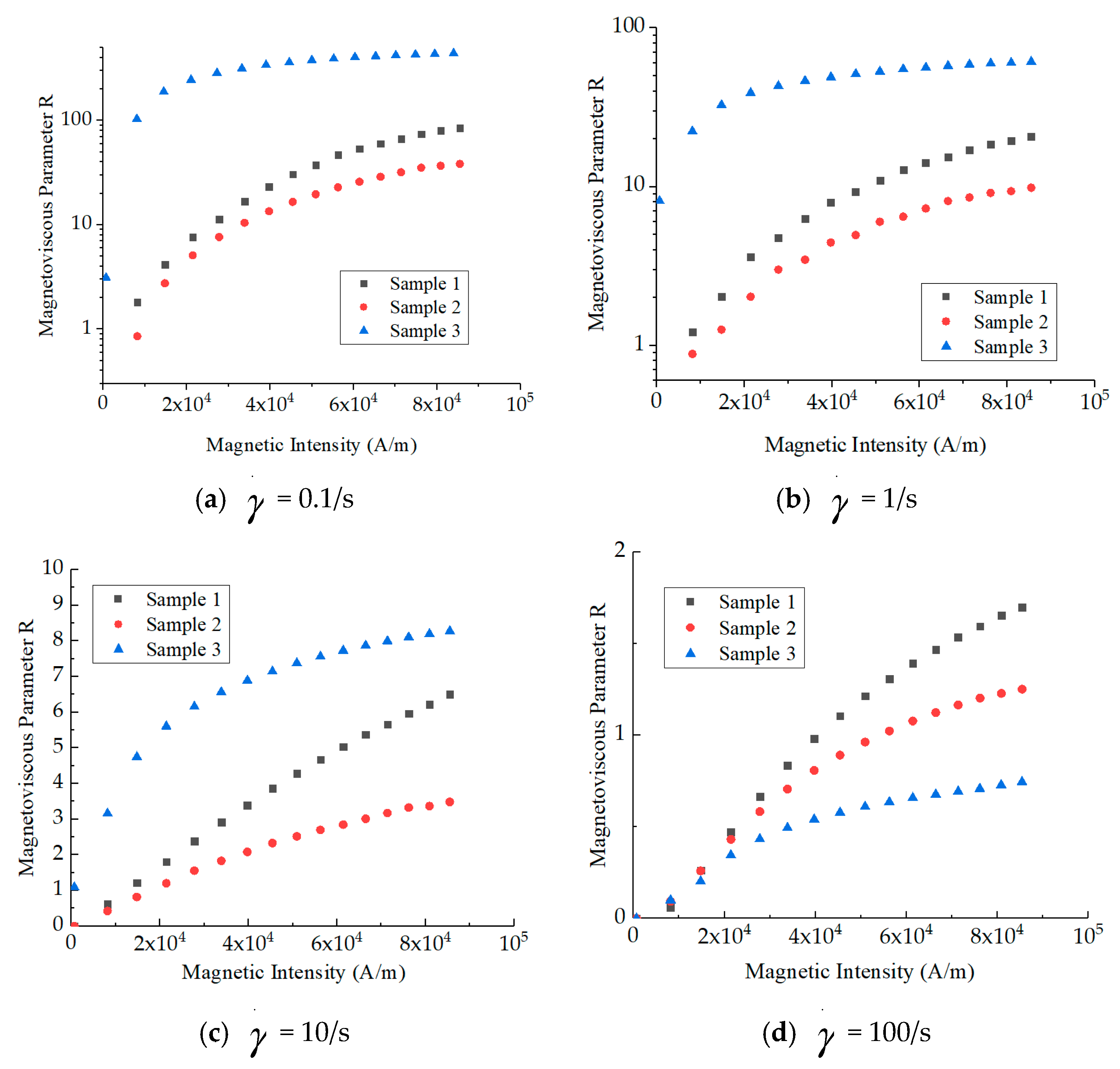
As shown in Figure 7, on the condition that the difference in values of viscosity is small, the magnetization intensity of magnetic fluids is influential and the magnetoviscous parameters of sample 1 are over those of sample 2 under different shear rates. The reason for this phenomenon is that the saturation magnetization of sample 1 is higher than that of sample 2, which increases the maximum number of particles in a chain from Equation (5), contributing to the magnetoviscous effect. The magnetoviscous parameters of sample 3 are higher than those of sample 1 and sample 2 under the shear rates of 0.1/s, 1/s and 10/s but lower under 100/s. When the shear rate is low (0.1/s, 1/s, 10/s), the single-chain structure of the magnetic fluid is linked in the high-viscosity base liquid, so that R of sample 3 is significantly higher than that of the other two kinds of magnetic fluids. In a strong shear field (100/s), the links between single chains of sample 3 decompose and the number of particles in the single chain decreases. Finally, all chains in the magnetic fluid are destroyed, and the magnetic viscosity effect is only caused by the response of individual particles to the magnetic field. In this condition, the intensity of the magnetoviscous effect lies in magnetization intensity of the magnetic fluid.
It can be seen from Figure 8, with the shear rate increasing from 0.01/s to 100/s, that the viscosity of sample 3 tremendously reduces by approximately 100 times, but the amplitude of variations of sample 1 and sample 2 is much smaller. The reason is that the base oil of sample 3 has many more macromolecular chains, and long chains that are aligned with the magnetic field direction are more sensitive to the change in shear rate. Even the spread of viscosity of sample 3 is the largest, and the viscosity under three different magnetic fields remains greater than 2800 mPa·s.
3.2. Washout Test of Magnetic Fluid
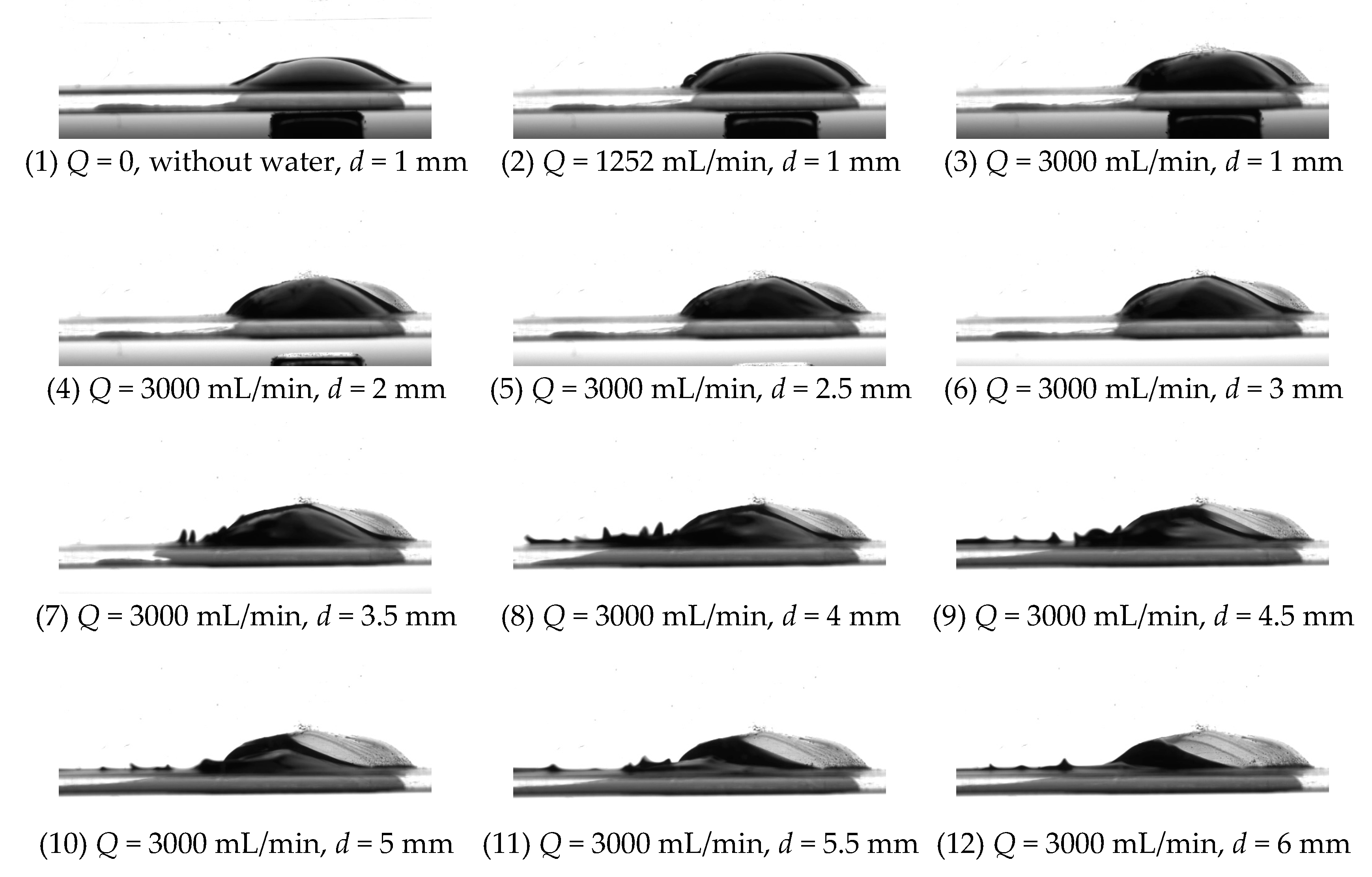
Initially, there was no gap between the magnet and the wall of the square tube of which the thickness was 1 mm. Thus, d is the distance from magnet to magnetic fluid base line, which is 1 mm initially. Q is the water flow rate and the direction of water flow is from right to left, as shown in Figure 9. After injecting the magnetic fluid of sample 1, the flow rate was enhanced gradually to 3000 mL/min. At the same time, the shape of the magnetic fluid is a little bit shaky but remains stable, as shown in Figure 9(3). As the magnet moved away, the magnetic force reduced, the shape of the magnetic fluid changed gradually to an oblique triangle and the long hypotenuse faced the direction that the current was coming from, as shown in Figure 9(4)–(6). The intensity of the magnetic fluid shaking was aggravated. When d = 3.5 mm, a small amount of magnetic fluid was washed away and flowed along the wall of the tube, which changed shape to become spines under the magnetic field, as shown in Figure 9(7). However, almost all the magnetic fluid washed a very short distance was pulled back by magnetic force, showing powerful self-recovery performance. The magnetic fluid started to be lost at the moment of d = 4 mm, and magnetic force was too weak to bring the magnetic fluid back. When d > 4 mm, the rate of washing out accelerated and the volume of magnetic fluid also affected the rate. When the flow rate is constant, the flow velocity is inversely proportional to sectional area, and the reduction of magnetic fluid volume causes the increase in the flow velocity of water over it.
Due to the magnetic field intensity decreasing with the distance from the magnet increasing, the Rosensweig–Kelvin–Helmholtz instability tends to occur at the interface between two liquids. Meanwhile, the velocity gradient of two liquids is also different, which leads to gradual removal of the magnetic fluid through friction.
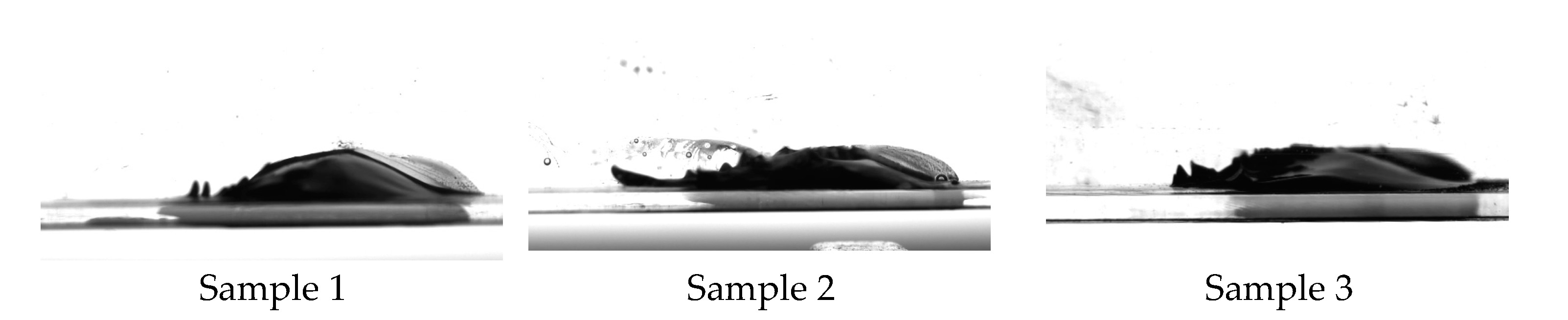
We tested all samples and found that the washout process of the magnetic fluid droplet was divided into three stages. In the first stage, the magnetic fluid surface was shaking under the wash of the current, but no part of the droplet was swept away. In this stage, the increasing velocity of water flow enhanced the fluctuation and shaking frequency and the surface shaking and fluctuation was like the shearing effect which reduced the viscosity of the magnetic fluid and made it easier to wash away. In the second stage, several parts of the droplet of a convex shape were continually washed away for a very short distance and were immediately pulled back by magnetic force. The speed of shaking and the frequency of producing spikes of sample 3 were much slower than that of the other two samples. In the third stage, more parts of the droplet were continually washed away until there was a small piece of magnetic fluid and a thin layer of magnetic fluid against the bottom wall. According to Equation (2), the total force of the magnetic fluid is directly proportional to M and the further the magnetic fluid is from the magnet, the weaker M is, which reduces the magnetic force. When the magnetic field intensity declined, the pieces of droplet far from the magnet were gradually washed away until the magnetic force on the remaining volume was big enough to withstand the current. That is how it affects the residual volume of the droplet. Images of three samples in an unstable state are shown in Figure 10.
What is noteworthy is that the distances from the magnet to MF when the magnetic fluid started being washed away are different for the three samples. In order to study the relationship between magnetic field intensity and washout, we recorded the distance from magnet to MF when first magnetic droplet started being washed away and defined this distance as the critical distance (e.g., Figure 9(7)).
The height of the magnetic fluid droplet is 2 mm and the length of it is 7.3 mm. Considering unsaturation of magnetic fluid under the magnetic field, the magnetization was calculated by interpolation. The magnetic fluid is superparamagnetic material, so there is no demagnetizing field caused by magnetic fluid. The magnetic field intensity was calculated by the finite-element method and the equations are as follows:
where is the magnetic induction intensity vector, is the magnetic intensity vector, is the magnetic potential. The magnetic induction intensity on the path increases with the decreasing of the distance from the center of the upper face of the magnet.
The magnetic field distribution of the magnet was calculated, as shown in Figure 11. The magnetic induction intensity on the horizontal line at half the height of the droplet was obtained.
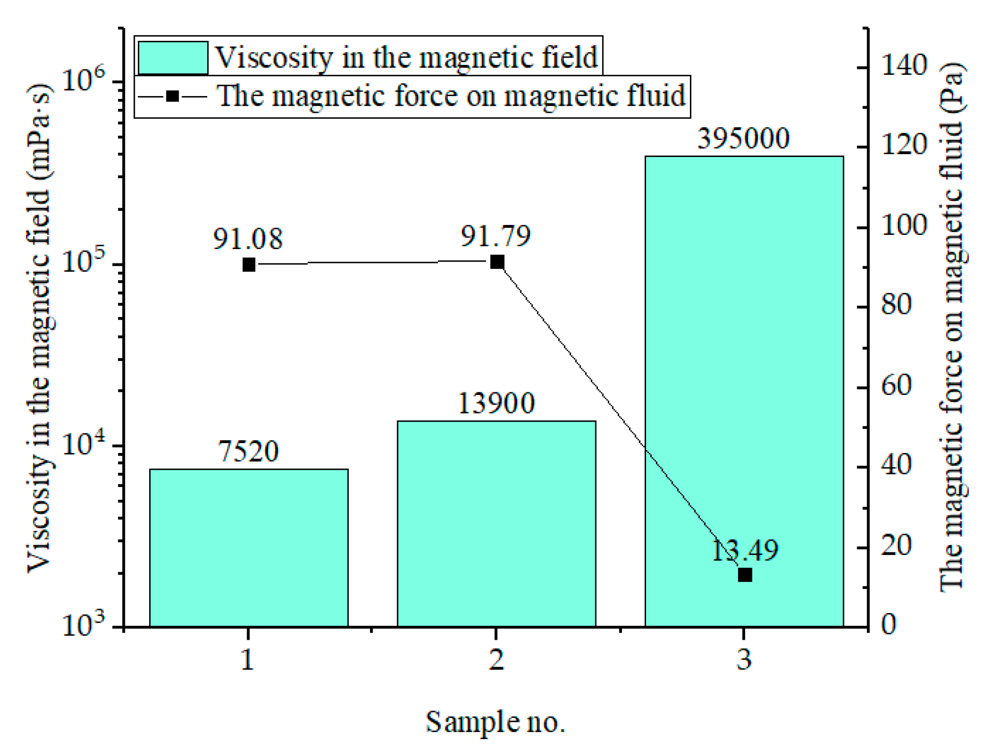
The magnetic force applied to the magnetic fluid droplet can be calculated using Equation (2). The critical distance and the force on each sample are presented in Table 2. The magnetic force increases with the distance decreasing. From Figure 12, we can see that the minimum magnetic force decreases with the increasing of viscosity. It indicates that the higher viscosity can prevent magnetic fluid from being washed away with lower magnetic force.
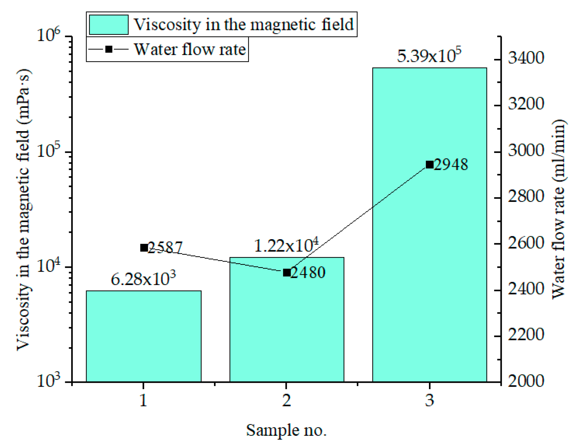
For sample 3, whose viscosity is 52.52 times greater than that of sample 1, the minimum magnetic force at which the drop is not washed away is 6.75 times less, which reveals the great influence of viscosity on washout resistance. In steady-state conditions, magnetic, scour force and viscosity forces are in balance, while magnetic fluid of higher viscosity requires lower magnetic force to remain stationary. The critical flow rates were obtained by fixing the distance between magnet and magnetic fluid, shown in Figure 13. Sample 3 of higher viscosity can resist a higher flow rate. Due to the delicate difference of viscosity between sample 1 and sample 2 and higher saturation magnetization of sample 1, the critical flow rates of sample 1 and sample 2 are not obvious.
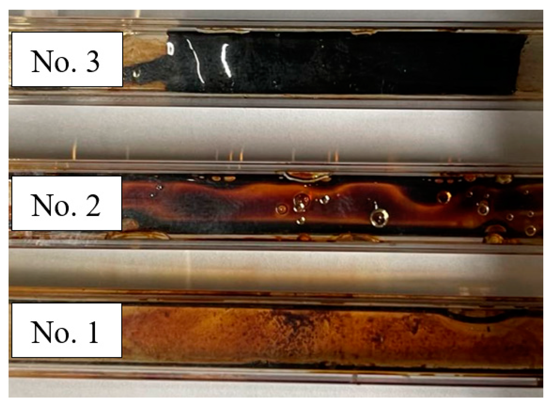
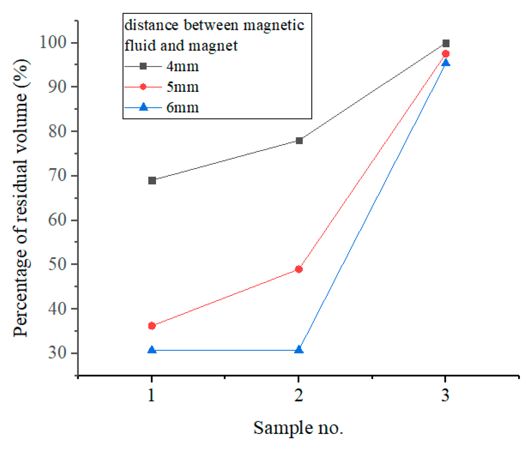
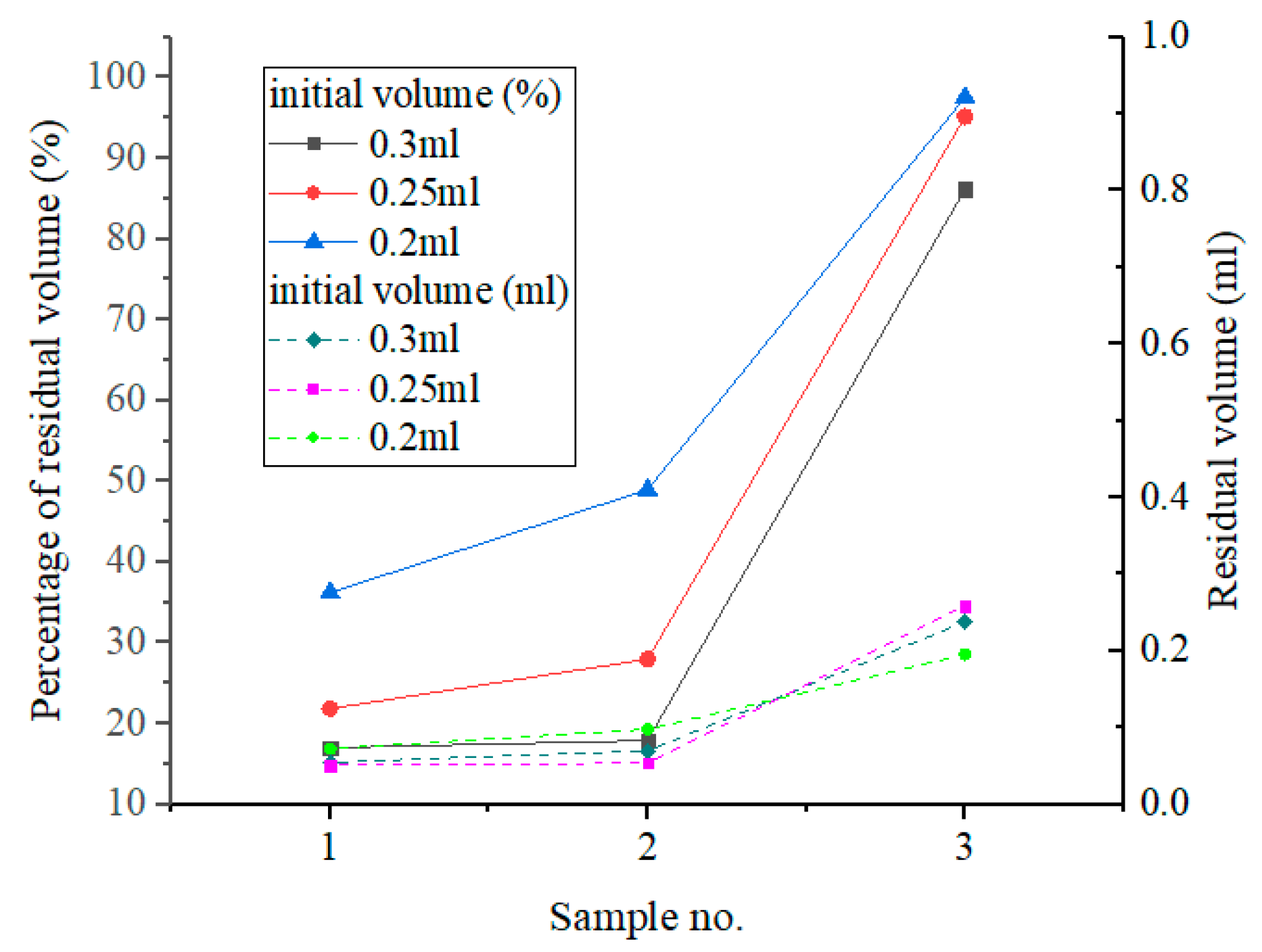
We carried out multiple washout tests with water flow of 2550 L/min and the washout time for each test was 10 min. The injection volume of samples was measured by injectors. The tubes after experiments with the same initial volume before blow-drying are shown in Figure 14 and the residual volume in descending order is 3, 2, 1. The tubes and magnetic fluid after washout experiments were blown dry at room temperature and their qualities were measured by a precision balance. We compared the residual volume of three samples after washout with different distances and initial volumes and the results are shown in Figure 15 and Figure 16.
Due to the magnetic field, there was a droplet of each sample left in the tube. As shown in Figure 15, decreasing the distance between magnet and magnetic fluid actually increased the residual volume in the tube, exactly like the trend observed in the washout experiment. The percentage of residual volume had a positive correlation with magnetic field. Figure 16 illustrates the trend that the percentage of residual volume increases with the sample number (or viscosity). The effect of magnetic field on magnetic fluid is also shown, in which residual volumes for each sample are almost the same. According to Equation (2) and calculation result of the magnetic field, the magnet can only supply enough magnetic intensity gradient in a particular area. So, the finite volume of the magnetic fluid was limited by the magnetic field and stayed in the tube and the rest was washed away by water flow due to insufficiency of the magnetic force.
4. Conclusions
In this study, magnetic fluids prepared with three kinds of carrier fluid of different viscosities were used to test the washout resistance and the specific conclusions are as follows:
- (1)
- The high-viscosity magnetic fluids were prepared with three kinds of mineral oil and the magnetoviscous effect of the three samples was studied. The viscosity of the three samples decreased at most by about 100 times with the shear rate increasing.
- (2)
- We designed and built a washout experimental platform and observed and summarized three phases of magnetic fluid washout. The magnetic fluid of higher viscosity can resist the same water flow with as little as 0.148 times the magnetic force than that of lower viscosity. Magnetic fluid of higher viscosity requires lower magnetic force to remain stationary. We also studied the relationship between viscosity and residual volume after washout in a quantitative way. From this research, it can be concluded that the viscosity of the magnetic fluid has a significant influence on washout resistance.
- (3)
- The ability to modify viscosity of magnetic fluid and resist washout in diverse operating environments is a crucial ingredient in developing liquid seals based on ferrofluids.
Author Contributions
Conceptualization, Z.L.; methodology, Z.L.; formal analysis, Y.L.; investigation, Z.L. and S.H.; data curation, Z.L. and S.H.; writing—original draft preparation, Z.L.; writing—review and editing, Z.L., Y.L. and D.L.; supervision, D.L.; project administration, D.L.; funding acquisition, D.L. All authors have read and agreed to the published version of the manuscript.
Funding
This research was funded by the National Key R&D Program of China (grant no. 2020YFB2006900), the National Major Scientific Research Instrument Development Project (grant no. 51927810) and National Natural Science Foundation of China (grant no. 51735006).
Institutional Review Board Statement
Not applicable.
Informed Consent Statement
Not applicable.
Data Availability Statement
Data are available from the authors upon reasonable request.
Conflicts of Interest
The authors declare no conflict of interest.
References
- Odenbach, S. Ferrofluids—Magnetically controlled suspensions. Colloids Surf. A Physicochem. Eng. Asp. 2003, 217, 171–178. [Google Scholar] [CrossRef]
- Kadau, H.; Schmitt, M.; Wenzel, M.; Wink, C.; Maier, T.; Ferrier-Barbut, I.; Pfau, T. Observing the Rosensweig instability of a quantum ferrofluid. Nature 2016, 530, 194–197. [Google Scholar] [CrossRef] [PubMed]
- Andrei, O.E.; Bica, I. Some mechanisms concerning the electrical conductivity of magnetorheological suspensions in magnetic field. J. Ind. Eng. Chem. 2009, 15, 573–577. [Google Scholar] [CrossRef]
- Omidbeygi, F.; Hashemabadi, S.H. Experimental study and CFD simulation of rotational eccentric cylinder in a magnetorheological fluid. J. Magn. Magn. Mater. 2012, 324, 2062–2069. [Google Scholar] [CrossRef]
- Szydlo, Z.; Matuszewski, L. Experimental research on effectiveness of the magnetic fluid seals for rotary shafts working in water. Pol. Marit. Res. 2007, 14, 53–58. [Google Scholar] [CrossRef]
- Szydlo, Z.; Szczech, M. Investigation of Dynamic Magnetic Fluid Seal Wear Process in Utility Water Environment. Key Eng. Mater. 2011, 490, 143–155. [Google Scholar] [CrossRef]
- Matuszewski, L.; Szydlo, Z. Life tests of a rotary single-stage magnetic-fluid seal for shipbuilding applications. Pol. Marit. Res. 2011, 18, 51–59. [Google Scholar] [CrossRef]
- Mitamura, Y.; Takahashi, S.; Amari, S.; Okamoto, E.; Murabayashi, S.; Nishimura, I. A magnetic fluid seal for rotary blood pumps: Effects of seal structure on long-term performance in liquid. J. Artif. Organs 2011, 14, 23–30. [Google Scholar] [CrossRef] [PubMed]
- Mitamura, Y.; Takahashi, S.; Amari, S.; Okamoto, E.; Murabayashi, S.; Nishimura, I. A magnetic fluid seal for rotary blood pumps: Long-term performance in liquid. Phys. Procedia 2010, 9, 229–233. [Google Scholar] [CrossRef]
- Kim, Y.S.; Kim, Y.H. Application of ferro-cobalt magnetic fluid for oil sealing. J. Magn. Magn. Mater. 2003, 267, 105–110. [Google Scholar] [CrossRef]
- Kurfess, J.; Müller, H.K. Sealing liquids with magnetic liquids. J. Magn. Magn. Mater. 1990, 85, 246–252. [Google Scholar] [CrossRef]
- Szczech, M. Experimental Study on the Leak Mechanism of the Ferrofluid Seal in a Water Environment. IEEE Trans. Magn. 2021, 57, 1–10. [Google Scholar] [CrossRef]
- Singh, C.; Das, A.K.; Das, P.K. Single-mode instability of a ferrofluid-mercury interface under a nonuniform magnetic field. Phys. Rev. E 2016, 94, 012803. [Google Scholar] [CrossRef]
- Kögel, A.; Völkel, A.; Richter, R. Calming the waves, not the storm: Measuring the Kelvin–Helmholtz instability in a tangential magnetic field. J. Fluid Mech. 2020, 903, A47. [Google Scholar] [CrossRef]
- Völkel, A.; Kögel, A.; Richter, R. Measuring the Kelvin-Helmholtz instability, stabilized by a tangential magnetic field. J. Magn. Magn. Mater. 2020, 505, 166693. [Google Scholar] [CrossRef]
- Cui, G.; Jacobi, I. Magnetic control of ferrofluid droplet adhesion in shear flow and on inclined surfaces. Langmuir 2020, 36, 10885–10891. [Google Scholar] [CrossRef] [PubMed]
- Bohlius, S.; Brand, H.R.; Pleiner, H. Rosensweig instability of ferrogel thin films or membranes. Eur. Phys. J. E 2008, 26, 275–282. [Google Scholar] [CrossRef] [PubMed]
- Li, W.; Li, Z.; Cheng, J. Effect of turbulence intensity of fluid medium interface layer on magnetic liquid seal in liquid environment. Chin. J. Mech. Eng. 2021; epub ahead of print. [Google Scholar]
- Li, Z.; Li, D.; Chen, Y. Influence of viscosity and magnetoviscous effect on the performance of a magnetic fluid seal in a water environment. Tribol. Trans. 2018, 61, 367–375. [Google Scholar] [CrossRef]
- Mitamura, Y.; Yano, T.; Nakamura, W. A magnetic fluid seal for rotary blood pumps: Behaviors of magnetic fluids in a magnetic fluid seal. Bio-Med. Mater. Eng. 2013, 23, 63–74. [Google Scholar] [CrossRef] [PubMed]
- Rosensweig, R.E. Ferrohydrodynamics; Cambridge University Press: Cambridge, UK, 1985. [Google Scholar]
- Pop, L.M.; Odenbach, S.; Wiedenmann, A.; Matoussevitch, N.; Bönnemann, H. Microstructure and rheology of ferrofluids. J. Magn. Magn. Mater. 2005, 289, 303–306. [Google Scholar] [CrossRef]
Figure 1.
Magnetization curves of three engine oil-based magnetic fluids.

Figure 2.
Experimental platform for washout test. 1—Pump. 2—Flow meter. 3—Pump flow regulator. 4—Flow indicator. 5—Black and white camera. 6—Square tube. 7—Backlight. 8—Manual lift guide rail. 9—Computer. 10—Water tank. 11—Height adjustment knob.
Figure 2.
Experimental platform for washout test. 1—Pump. 2—Flow meter. 3—Pump flow regulator. 4—Flow indicator. 5—Black and white camera. 6—Square tube. 7—Backlight. 8—Manual lift guide rail. 9—Computer. 10—Water tank. 11—Height adjustment knob.

Figure 3.
Photograph of washout progress.

Figure 4.
The magnetic droplet state with different distances between the magnet and magnetic fluid.
Figure 4.
The magnetic droplet state with different distances between the magnet and magnetic fluid.

Figure 5.
Change in viscosity of three types of magnetic fluids under different shear rates.

Figure 6.
Magnetoviscous parameter R of three types of magnetic fluids under different shear rates.

Figure 7.
Magnetoviscous parameter R of three types of magnetic fluids under different shear rates.

Figure 8.
Viscosity of three types of magnetic fluids under different magnetic fields.

Figure 9.
Images of magnetic fluid shape of washout under different d.

Figure 10.
Images of magnetic fluid shape in an unstable state.

Figure 11.
Calculation result of the finite-element method.

Figure 12.
Magnetic force and viscosity under the washout test.

Figure 13.
Critical flow rate and viscosity under the washout test.

Figure 14.
The tube after washout experiment and before blow-drying.

Figure 15.
Residual volume with different distances (initial volume is 0.2 mL).

Figure 16.
Residual volume with different initial volumes (distance between magnetic fluid and magnet is 5 mm).
Figure 16.
Residual volume with different initial volumes (distance between magnetic fluid and magnet is 5 mm).


Table 1.
Properties of magnetic fluids and the base liquids.
| Sample No. | Density (g/mL) | Zero Magnetic Field Viscosity (mPa·s) (100/s) | Saturation Magnetization (KA/m) |
|---|---|---|---|
| 1 | 1.4057 | 297.4 | 44.5 |
| 2 | 1.3569 | 377.9 | 38.7 |
| 3 | 1.4140 | 1456.9 | 37.0 |
| 4 | 0.8176 | 1.9 | - |
| 5 | 0.8343 | 14.5 | - |
| 6 | 0.8744 | 46.2 | - |
Table 2.
The magnetic force on magnetic fluid.
| Sample No. | The Distance from Magnet to MF When Magnetic Fluid Started Being Washed Away (mm) | The Magnetic Force on Magnetic Fluid (Pa) |
|---|---|---|
| 1 | 4.66 | 90.08 |
| 2 | 4.62 | 91.79 |
| 3 | 7.5 | 13.49 |
Disclaimer/Publisher’s Note: The statements, opinions and data contained in all publications are solely those of the individual author(s) and contributor(s) and not of MDPI and/or the editor(s). MDPI and/or the editor(s) disclaim responsibility for any injury to people or property resulting from any ideas, methods, instructions or products referred to in the content. |
© 2023 by the authors. Licensee MDPI, Basel, Switzerland. This article is an open access article distributed under the terms and conditions of the Creative Commons Attribution (CC BY) license (https://creativecommons.org/licenses/by/4.0/).
Share and Cite
MDPI and ACS Style
Li, Z.; Li, D.; Li, Y.; Han, S. Influence of High Viscosity and Magnetoviscous Effect on the Washout Resistance of Magnetic Fluid. Magnetochemistry 2023, 9, 134. https://doi.org/10.3390/magnetochemistry9050134
AMA Style
Li Z, Li D, Li Y, Han S. Influence of High Viscosity and Magnetoviscous Effect on the Washout Resistance of Magnetic Fluid. Magnetochemistry. 2023; 9(5):134. https://doi.org/10.3390/magnetochemistry9050134
Chicago/Turabian StyleLi, Zixian, Decai Li, Yanwen Li, and Shuntao Han. 2023. "Influence of High Viscosity and Magnetoviscous Effect on the Washout Resistance of Magnetic Fluid" Magnetochemistry 9, no. 5: 134. https://doi.org/10.3390/magnetochemistry9050134
Note that from the first issue of 2016, this journal uses article numbers instead of page numbers. See further details here.