Article

Novel Concentric Magnetic Continuum Robot with Multiple Stiffness Modes for Potential Delivery of Nanomedicine

1
State Key Laboratory of Robotics, Shenyang Institute of Automation, Chinese Academy of Sciences, Shenyang 110016, China
2
Institutes for Robotics and Intelligent Manufacturing, Chinese Academy of Sciences, Shenyang 110016, China
3
University of Chinese Academy of Sciences, Beijing 100049, China
*
Author to whom correspondence should be addressed.
Magnetochemistry 2023, 9(5), 129; https://doi.org/10.3390/magnetochemistry9050129
Submission received: 7 April 2023 / Revised: 6 May 2023 / Accepted: 9 May 2023 / Published: 12 May 2023
(This article belongs to the Section Magnetic Materials)

Abstract

:
The utilisation of miniature robots has become essential in the domain of minimally invasive surgery and long-distance delivery of nanomedicine. Among these, the miniature magnetic continuum robot (MCR) stands out because of its simple structure and dexterity, which allow it to penetrate small cavities, transport specialised tools such as a laser, and deliver medications to support surgical treatment. Nevertheless, because of their soft bodies with a single stiffness, conventional MCRs have limited controllability when navigating through intricate cavities. To address this limitation, we propose a novel concentric magnetic continuum robot (C-MCR) comprising a concentric magnetic catheter with a guidewire having varying stiffness. The C-MCR allows substantial curvature bending owing to its difference in stiffness, and its detachable nature allows it to have four working modes to adapt to specific application requirements with improved stiffness controllability. Experiments demonstrate the ability of the C-MCR to navigate complex pathways and deliver nanomedicines over long distances to specific areas via its internal channels using a large homemade eight-coil electromagnetic system. The C-MCR offers promising application prospects for the long-distance delivery of tailored nanomedicines because of its simple operation, reduced risks, and larger attainable workspace.

1. Introduction

Targeted nanomedicines have drawn significant attention as a strategy for cancer diagnosis and treatment strategy. Nevertheless, their delivery efficiency to solid tumours is limited, with a median of just 0.7% [1]. Although local targeting of nanomedicines has been successful in various organs, such as the brain, bladder, and stomach [2,3,4,5,6], their small size makes them susceptible to external environmental factors, resulting in suboptimal delivery. To address this challenge, miniature magnetic continuum robots (MCRs) have emerged as a viable alternative for improving the long-distance transport of nanomedicines because of their potential for actively navigating intricate pathways in a remotely controllable manner [7,8], as shown in Figure 1.
Although conventional continuum robots are more flexible and better adapted to surgical applications than rigid robots, their sizes are limited by their mechanical construction, materials, and control methods [9]. In contrast, magnetic control offers a remote wireless drive technique that provides precise control while shrinking the size of continuum robots. This unique feature enables surgeons to remotely control continuum robots to perform various surgical tasks, such as brain, eye, gastrointestinal, and other surgeries [10,11].
Research on MCRs has primarily focused on miniaturisation, dexterity, and functionalisation to expand their potential applications [12,13]. Using unique manufacturing techniques, the soft body of MCR can be uniformly distributed with ferromagnetic particles and covered with a hydrogel skin, providing them with the capabilities of omnidirectional steering and self-lubrication [14]. Additionally, the inclusion of embedded Hall-effect sensors enables MCRs to receive position feedback [15]. Specially designed catheter tips have been developed to treat blood clots, panretinal and twin-to-twin transfusion syndrome, and other diseases [16,17,18,19]. However, conventional MCRs have encountered issues with poor controllability owing to their soft bodies. To address this issue, researchers have explored various techniques for improving the controllability of MCRs. One viable approach involves achieving variable catheter stiffness via materials such as a low-melting-point alloy (LMPA) and conductive shape memory polymer (CSMP) [20,21,22,23]. Furthermore, in our previous work, we designed MCRs embedded with opposing magnets that enable soft catheters to actively deform in multiple modes, thereby increasing their dexterity [24,25,26]. However, most of these methods have fixed spacing between magnetic substances, which still limits the dexterity of MCRs for complicated and tortuous actual paths in the human body. Additionally, the opposing magnets fail to fully address issues caused by the lack of stiffness of the catheters, such as the inability to advance when they encounter obstructions. As a solution to these problems, we propose the C-MCR that employs two materials with different stiffness. The magnetic catheter and magnetic guidewire are independent of each other, and the relative position of the magnets can be adjusted and controlled according to different cavities, providing enhanced adaptability.
A dependable magnetic navigation system (MNS) is crucial for the adequate functioning of MCRs. Depending on the magnetic-field generation method, MNS can be classified into two primary categories: permanent magnets and electromagnets [27]. Although permanent magnets can manipulate the orientation of the MCRs to subject them to force or torque [28,29,30,31], the magnetic field size is restricted to a certain range because of the limited size of permanent magnets. For a larger magnetic field over a certain range, a large permanent magnet and a robot arm connected to it are required. However, the electromagnets generate a current-dependent magnetic field when energised to control the MCRs. In the case of electromagnets with an obvious orthogonal distribution, the working area is at the centre [32,33,34,35]. Distributed electromagnets allow for better layout constraints and more efficient energy use [36,37,38,39]. Furthermore, mobile-distributed electromagnetic equipment is being investigated to obtain a larger working space [40,41,42]. For the experiments detailed in this paper, we employed a large, homemade eight-coil electromagnetic system (Figure 1).
In this paper, we present a novel C-MCR that addresses the issue of poor controllability in conventional MCRs. The C-MCR consists of two concentric parts: a magnetic catheter and a magnetic guidewire. The C-MCR achieves controlled stiffness by combining the soft magnetic catheter with a large magnetic field response and the hard magnetic guidewire with good controllability. Compared with conventional MCRs, the C-MCR also offers mode selection and large curvature bending capabilities.
The following are the primary contributions of our work:
(1)
We propose the C-MCR, a concentric magnetic continuum robot that combines the advantages of soft and hard magnetic materials to achieve controlled stiffness;
(2)
We analyse the characteristics and potential applications of the four working modes of the C-MCR based on the response difference in different directions of the magnetic field;
(3)
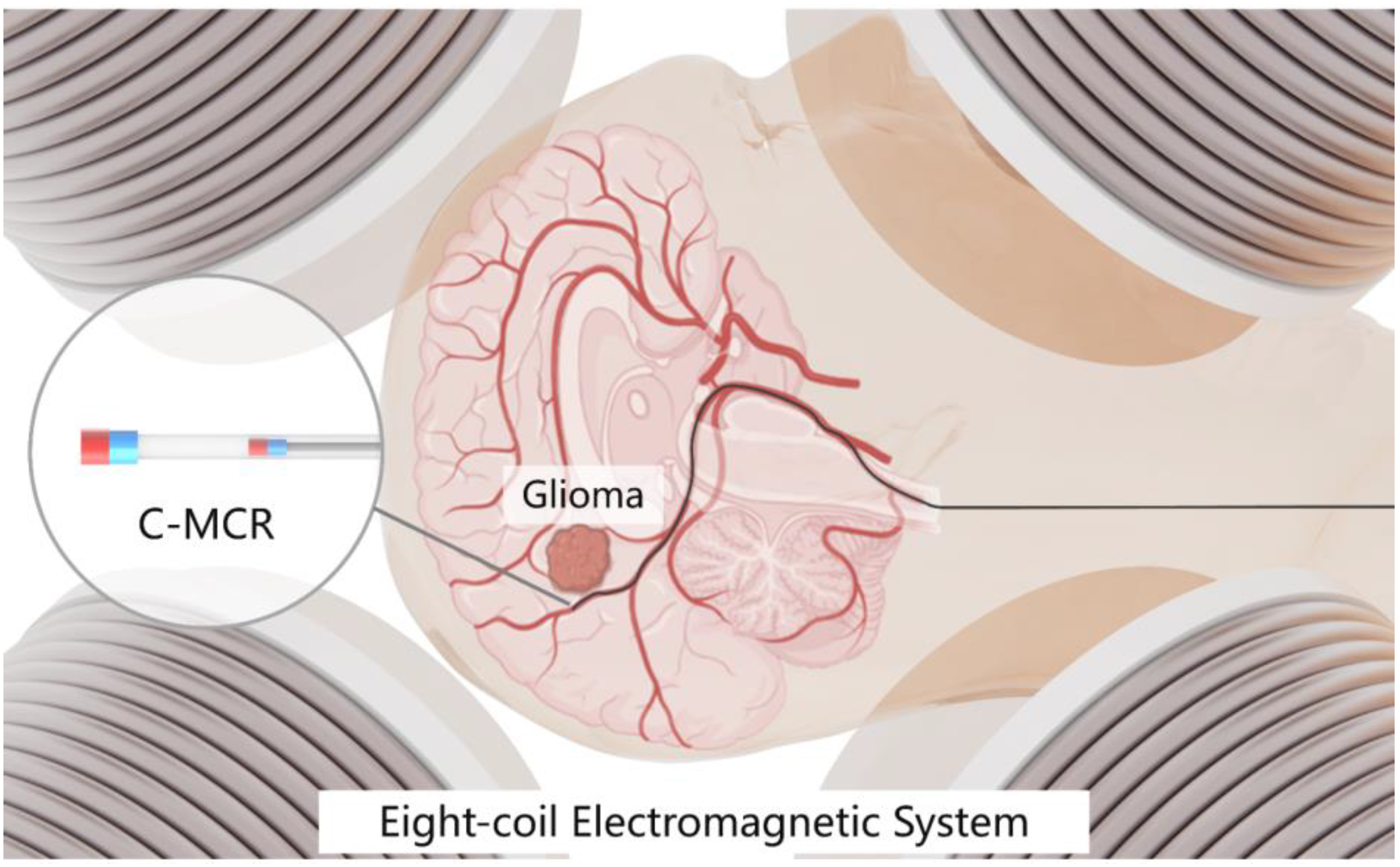
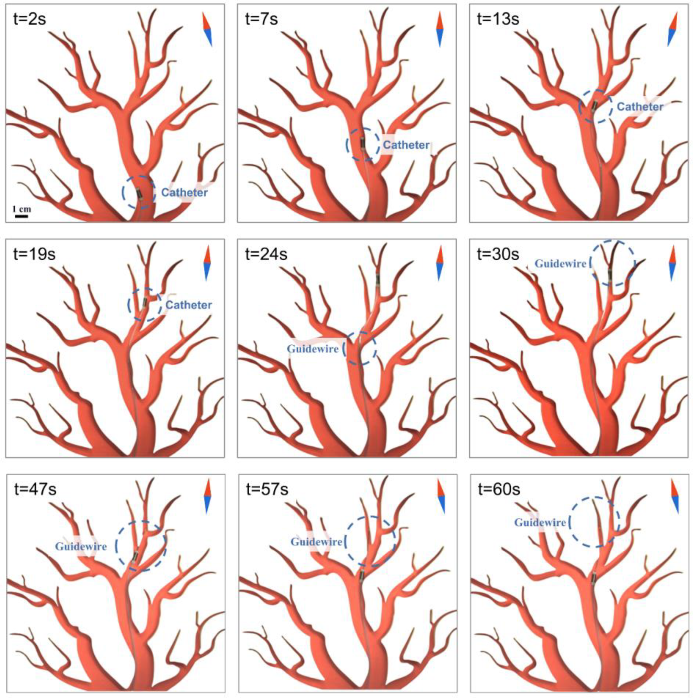
We demonstrate experimentally the ability of the C-MCR to navigate through complex cavities and address the issue of long-distance targeted nanomedicine delivery using the homemade eight-coil electromagnetic system.

2. Materials and Methods

2.1. Materials

N52 neodymium magnets were tailored to our specifications by Nanjing Chuangken Magnet Co. (Nanjing, China) and hollow rubber tubing was purchased from the Chunshi flagship store (Shanghai, China). Meso-Tetra(p-hydroxyphenyl) porphine (m-THPP) and dimethylsulfoxide (DMSO) were sourced from Aladdin Scientific Corp. Fluorenylmethoxycarbonyl-Leucine-Leucine-Leucine-OMe (Fmoc-L3-OMe) was obtained from NJ Peptide Company (Nanjing, China). The murine glioma cell line GL-261 was obtained from American Type Culture Collection (Manassas, VA, USA). All reagents were employed as received. Ultrapure water (Milli-Q) with a resistivity of 18.2 MΩ·cm was used for all experiments.

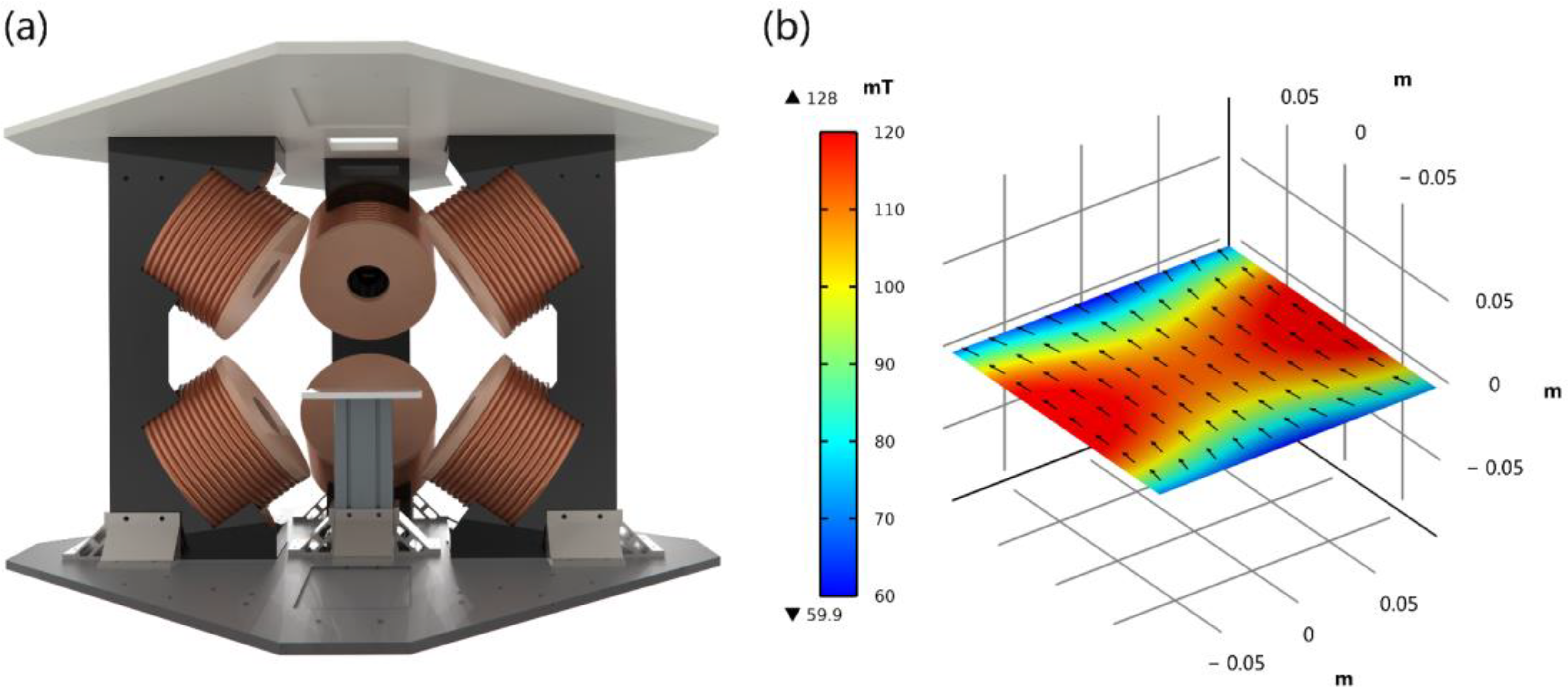
2.2. Magnetic Navigation System

To ensure a stable magnetic field for the C-MCR, we designed and built an eight-coil electromagnetic system, as shown in Figure 2. The system can produce a stable magnetic field in a 300 mm diameter spherical working space with a 120 mT magnetic field generated at the sphere’s centre.

2.3. Concentric Magnetic Continuum Robot

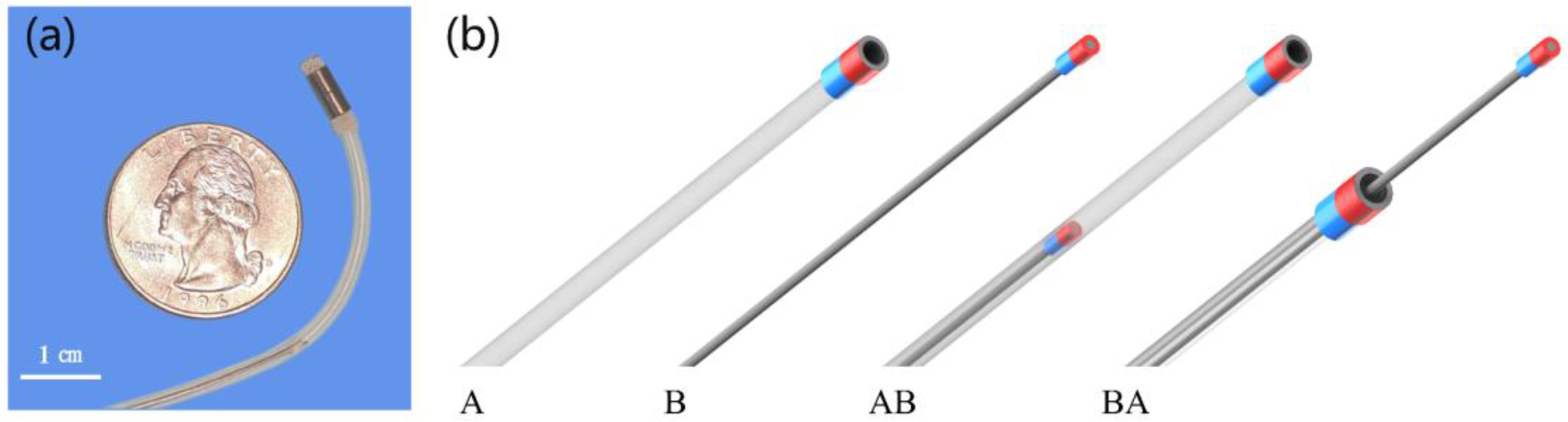
2.3.1. Structure Design
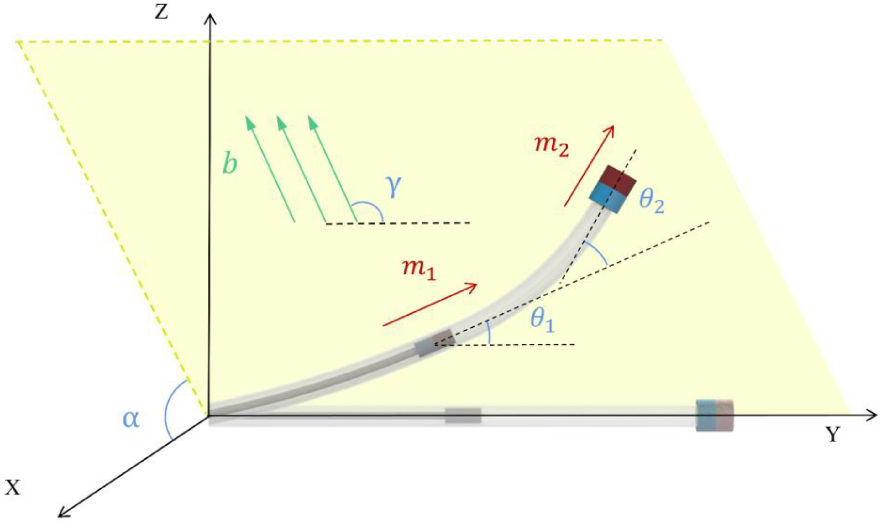
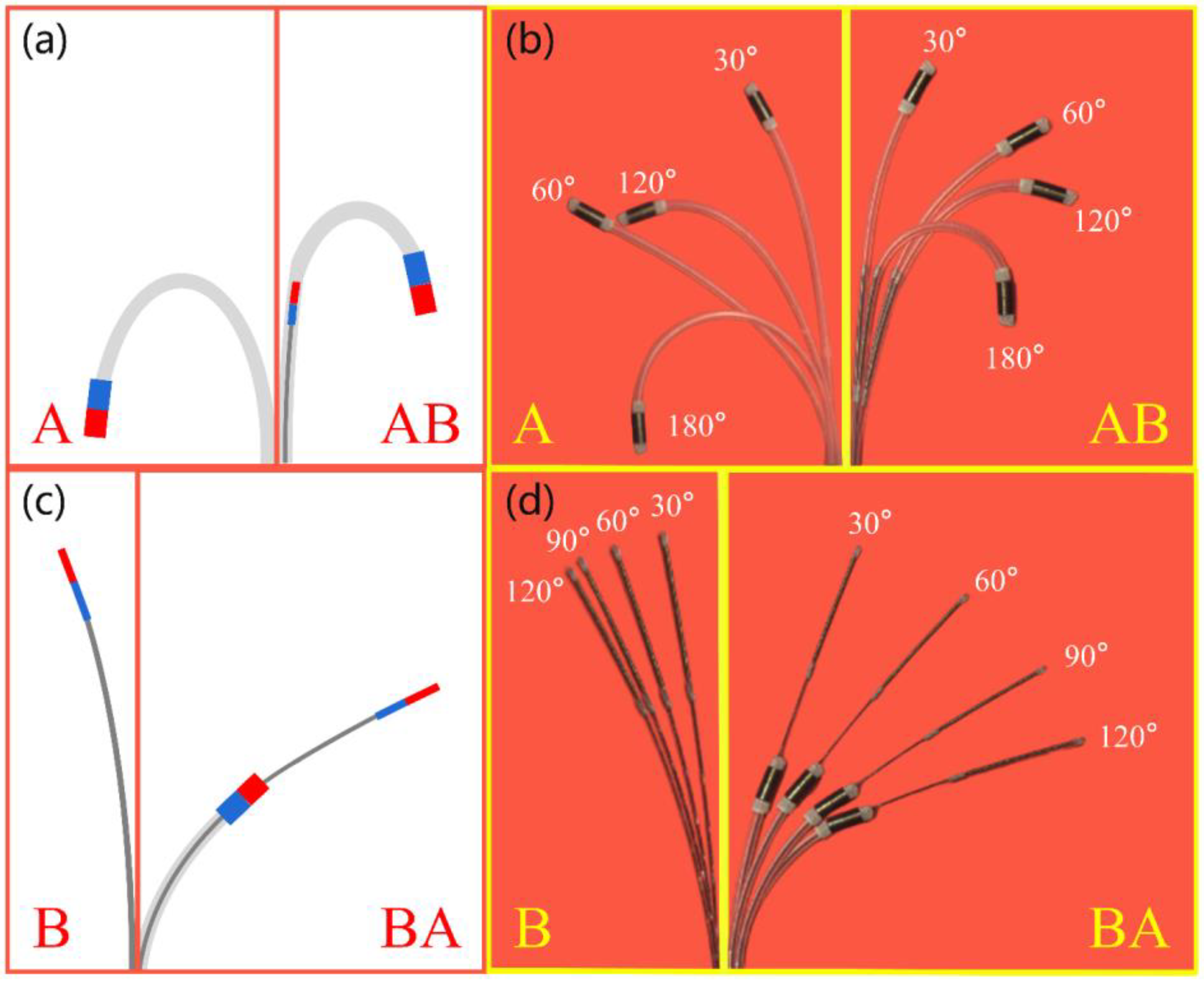
The C-MCR was designed to address the challenges associated with controlling and large curvature bending of conventional MCRs with too-soft bodies. The C-MCR consists of a hollow rubber catheter with an inner diameter of 1 mm, an outer diameter of 2 mm, and a 0.3 mm diameter solid nickel–titanium alloy guidewire. The significant discrepancy in stiffness between the two components can be attributed to the difference in materials. The front end of the catheter is equipped with two axially magnetised, hollow cylindrical N52 neodymium magnets, measuring 2.1 mm in inner diameter, 3 mm in outer diameter, and 3 mm in length. Similarly, the front of the guidewire features ten axially magnetised, hollow cylindrical N52 neodymium magnets, each measuring 0.4 mm in inner diameter, 0.6 mm in outer diameter, and 2 mm in length (Figure 3a).
Because both the catheter and guidewire have magnets at their front ends, they can respond to alterations in the magnetic field. However, owing to the varying stiffnesses of their soft parts, they respond differently to the same magnetic field. We have astutely used this difference to make the C-MCR available in four different modes (Figure 3b). Theoretically, Mode A is ideal for large-diameter and small-curvature cavities and can aid procedures such as drug delivery. Mode B is suitable for cavities with small diameters and curvatures. Mode AB is better suited for luminal tracts with greater curvature. The magnetic catheter provides a wider deflection angle to the magnetic guidewire in Mode BA, thereby creating a protective barrier. Based on these conjectures, we experimentally test these four working modes and provide a detailed analysis of their applications in the following sections.

2.3.2. Bending Mode

This section presents the classical AB bending model for the C-MCR, which serves as the basis for deriving the bending models for other modes. A homemade eight-coil electromagnetic system is used to control the magnetic field of the C-MCR. The magnitude of the dipole magnetic field produced by an individual electromagnetic coil is equivalent to the following equation:
B = μ 0 4 π p 3 3 ( m p ^ ) p ^ m ,
where p 3 denotes the position of the relative dipole, μ 0 = 4 π × 10 7 T m / A represents the vacuum permeability, and m indicates the dipole moment size. Notably, the strength of the magnetic field decreases at a rate of 3 as the distance increase.
The external magnetic field exerts a magnetic torque on the magnetised object, causing it to align with the field [43]. As shown in Figure 4, when the C-MCR undergoes a bending motion owing to the deflecting magnetic field, the magnetic torque t m i R 3 is generated in the bending plane, which can be expressed as follows:
t m i = m i b sin γ θ i i = 1,2 ,
where γ represents the pitch angle of the directional magnetic field b R 3 expressed in Equation (3). The magnetic moment of the i th magnet is denoted by m i and θ i represents the deflection angle of the i th small magnet. As shown in Figure 3, the C-MCR in classical mode comprises two small magnets. The first magnet is located close to the fixed position, and its deflection angle with respect to the y-axis is denoted by θ 1 . The second magnet is situated near the end of the tube, and its deflection angle with respect to the extension of the deflection direction of the first magnet is denoted by θ 2 .
b = A m sin γ cos α   sin γ sin α   cos γ T ,
where A m denotes the magnitude of the magnetic field, and α represents its yaw angle.
The recovery moment t r i R 3 for the C-MCR, which attempts to return to its original state, is equivalent to the following equation:
t r i = E i I A i θ i L C i           i = 1,2 ,
where E i and I A i represent the modulus of elasticity and area moment of inertia of the i th segment of the catheter, respectively, and L C i corresponds to the length between the end of the i th small magnet and the location at which the bending of that section occurs.
t m i = t r i           i = 1,2 ,
The steady state of the C-MCR is attained once Equation (5) is satisfied. It is possible to predict the deflection by tracing backwards.

2.4. Nanomedicine Preparation

We took 16 mg and 2 mg each of lyophilised Fmoc-L3-OMe and m-THPP and, respectively, dissolved them in 1 mL of DMSO. These solutions were mixed thoroughly in equal proportions. The resulting mixture was diluted tenfold by adding deionised water and agitating continuously. Subsequently, the mixture was centrifuged at 12,000 rpm for 10 min and then further diluted with DMEM medium to achieve the desired concentration.

2.5. Scanning Electron Microscopy

The micromorphology of the nanomedicine was examined using a Quattro S instrument (Thermo Fisher Scientific, Waltham, MA, USA) to capture a scanning electron microscopy (SEM) image. The nanomedicine suspension was uniformly applied onto a silicon wafer, dried, and then coated with a 20 nm thick gold film through ion sputtering.

2.6. Cell Culture

Commercially acquired GL-261 cells were cultivated in DMEM medium (Gibco), augmented with 10% fetal bovine serum (FBS) (Gibco), and 1% penicillin-streptomycin (HyClone), and incubated at 37 °C in a humidified atmosphere containing 5% CO2.

2.7. Cell Viability Test

The viability of primary glioma cancer cells was assessed using the CCK-8 kit (Dojindo, Japan), according to the manufacturer’s instructions. First, the desired concentration of the cell suspension was added to 96-well plates (0.1 mL per well) and incubated overnight. Subsequently, the nanomedicines carrying photosensitisers were added to the wells. Following a 5 h incubation period, red laser irradiation at 638 nm was administered to the sampling sites, and the incubation process was prolonged overnight. Finally, 10 μL of CCK-8 solution was added to each well and allowed to incubate in the dark for 2–4 h before being measured using a DNM-9602 G microplate reader (Perlong Medical, Beijing, China) with a wavelength of 450 nm.

2.8. Nanomedicine Delivery via C-MCR

Our homemade eight-coil electromagnetic system is capable of generating a magnetic field in any direction to guide the C-MCR. With the magnetic field deflection control and the advancing device, the C-MCR can precisely navigate through intricate cavities to reach the target location, such as a recess in a 3D-printed blood vessel-like model. To conduct the experiment, we placed a coverslip containing GL-261 cells in the recess. Upon reaching the target location, we removed the magnetic guidewire inside the magnetic catheter and injected the nanomedicine medium through the internal hollow cavity of the catheter using a syringe. After co-culturing the nanomedicine with the cells for 5 h, we captured the TIE image of the cells by Ti2-E inverted optical microscope (Nikon Corporation, Tokyo, Japan).

3. Experiments and Results

The C-MCR addresses the issue of poor controllability faced by conventional MCRs because of their softness. Leveraging the stiffness differential between the magnetic catheter and magnetic guidewire achieves variable stiffness, large-curvature bending, and four selectable working modes. We conducted experiments to evaluate three key aspects: four working modes, dexterity, and nanomedicine delivery. Based on the results of these experiments, we analyse and summarise the adaptability of the C-MCR to various application scenarios, its performance in vascular-like channels, and its efficacy in targeted nanomedicine delivery operations.

3.1. Four Working Modes

In this section, we present an experimental validation of the four working modes of the C-MCR (Mode A, B, AB, and BA) and investigate their unique responses to an identical magnetic field. Furthermore, we analyse the underlying causes of the observed response characteristics and explore their practical applicability.
Mode A and Mode B are two distinct modes, where Mode A pertains to a single magnetic catheter, and Mode B pertains to a single magnetic guidewire. The catheter body is constructed of soft rubber material, with a highly magnetic magnet at its front end, which makes it more responsive to changes in the magnetic field. Mode A is essentially a classical MCR, that satisfies the basic requirements for navigation in a simple large cavity. However, similar to most conventional MCRs, it suffers from poor controllability because of its too-soft body. In contrast, the guidewire body is composed of a hard nickel–titanium alloy with a small magnet that has a weaker front end owing to its size, resulting in a relatively small response to changes in the magnetic field. However, the hardness of the guidewire provides an unobstructed operation in scenarios such as thrombosis. We design the C-MCR to achieve controlled stiffness by ingeniously combining the catheter’s softness and the guidewire’s stiffness.
Figure 5a illustrates the classical deformations of Mode A and Mode AB. Mode AB is an extension of Mode A with a magnetic guidewire inserted into the catheter. With its greater stiffness, the magnetic guidewire provides more resistance to the deformation of the catheter near the fixed end. The test results, as shown in Figure 5b, demonstrate that the soft portion of Mode AB deforms similarly to that of Mode A, with the small magnets at the end of the catheter pointing in the same direction for both modes. However, the deformation of the catheter with the guidewire in Mode AB is restricted and smaller, permitting a larger curvature bend. This is evident from the difference in deformation between the two modes under a 180-degree magnetic field, as shown in Figure 5b. Furthermore, in Mode AB, the soft portion’s length can be adjusted to meet the required specifications.
Figure 5c illustrates the typical deformation of Mode B and Mode BA. Mode BA is the guidewire over the catheter based on Mode B. As shown in Figure 5d, Mode BA exhibits greater bending than Mode B under the same magnetic field, thereby addressing the issue of insufficient deformation owing to the excessive stiffness of the guidewire. Moreover, the external catheter offers additional protection to the guidewire during withdrawal, effectively preventing damage to the surrounding tissues, such as blood vessels, caused by the rigidity of the guidewire.

3.2. Dexterity

Dexterity is a crucial indicator of MCR and reflects the ability to navigate complex channels. By using 3D printing technology to fabricate a vessel-like channel and observing the C-MCR’s ability to navigate through it, we were able to gauge its dexterity. Figure 6 and the supported video demonstrate that the C-MCR in Mode AB can accurately reach the target location. In response to changes in the external magnetic field at 3 s, 8 s, and 20 s, the C-MCR successfully navigated the channel by steering itself in the direction of the magnetic field. The C-MCR demonstrated its ability to negotiate bends smoothly at 9 s, 14 s, and 19 s by manipulating the relative positioning between the inner guidewire and outer catheter. However, because of the softness of the catheter, its controllability during turning is suboptimal. The C-MCR can perform smoother turns by properly adjusting the position of the internal guidewire at the turning point and then utilising the external magnetic field.
The dexterity of the C-MCR in Mode BA is shown in Figure 7 and the supporting video. This task not only involves transitioning from Mode AB to Mode BA but also testing the ability to reach the two endpoints. In addition to the steering capability shown in Figure 6, the guidewire can extend through the internal hollow cavity of the catheter to reach more narrow places in 24 s to 30 s. Surprisingly, only the guidewire had difficulty reaching the endpoint at 30 s. However, this was achieved smoothly with the assistance of the external catheter. From 30 s to 60 s, the C-MCR deftly reached the other adjacent end via three operations: retreat, turn, and advance under Mode BA. Both experiments highlight the impressive dexterity of the C-MCR.

3.3. Nanomedicine Delivery

Owing to their small size, targeted nanomedicines have attracted extensive research in the area of long-distance delivery. The internal cavity of the C-MCR’s Mode A is a good conduit for the delivery of nanomedicines to specific locations. Figure 8a and the supported video show the efficient long-distance transport of nanomedicines by the C-MCR. A coverslip with cells grown over a 10 mm × 10 mm area was placed within the recess on the left side. The C-MCR could reach the recess smoothly by changing the magnetic field and advancing the catheter and guidewire. Once in position, the guidewire was removed, and the nanomedicine was injected into the specified recess using a syringe. At 42 s, it is evident that the nanomedicine in the DMEM medium is visibly transported to the intended location over a long distance. After that, we took TIE images of the cells after co-culturing them with nanomedicine for 5 h (Figure 8b). We prepared this nanomedicine incorporating the photosensitiser m-THPP. The m-THPP is a close congener of the approved photosensitiser 5,10,15,20-tetrakis(3-hydroxyphenyl)chlorin (m-THPC, temoporfin), and they can be used for photodynamic therapy of diseases of the brain, neck and skin diseases [44,45]. The SEM images (Figure 8c) demonstrate that the medicine is on the nanometre scale. By assaying cell viability using the CCK-8 kit, it is evident that low concentrations of the nanomedicine are innocuous to the cells in a light-deprived milieu (Figure 8d). However, when exposed to a laser with a central power point of 53.8 MW and a wavelength of 638 nm for 5 min, GL-261 cell viability declined as the concentration of the nanomedicine increased (Figure 8d). This demonstrates that nanomedicine can be used for photodynamic therapy of glioma cells. Additionally, this nanomedicine exhibits strong fluorescence emission properties, which can be easily visualised in a fluorescent environment. As seen in the TIE images (Figure 8b), the cells exhibit intense red fluorescence emission, which means that the cancer cells contain a large amount of nanomedicine. It confirms that the C-MCR delivered the nanomedicine to the specified location. Despite being a simple experiment, it successfully demonstrates the potential of the C-MCR to facilitate the long-distance transport of nanomedicines and offers promise for future applications in this field.

4. Discussion and Conclusions

Despite sharing similarities with the MCR with two small magnets in terms of navigation, the C-MCR has a simpler structure and a smaller form factor that allows greater dexterity and mode changes. Mode AB resolves the issue of poor controllability inherent in a too-soft catheter and allows bending with a large curvature. On the other hand, Mode BA addresses the limitations posed by an excessively stiff guidewire, enhances the magnetic field response, and safeguards the surrounding tissue. Moreover, Mode BA can reach narrower lumens compared to Mode AB, and its stiff anterior guidewire can pass through some vessel obstacles such as thrombus. The C-MCR achieves controlled stiffness with greater flexibility and adaptability by adjusting the relative positions of the small magnet at the front of the magnetic catheter and the small magnet at the front of the magnetic guidewire. The surgeon can switch freely between these four working modes based on specific cavity requirements. In contrast to the conventional MCR, the C-MCR can achieve a greater bending curvature, controllable stiffness, and mode selectivity. Furthermore, our experiments show that the C-MCR not only possesses exceptional dexterity but also provides a potential solution to the problem of targeted long-range delivery of nanomedicines. Theoretically, the C-MCR can be utilised for laser irradiation, internal cavity sample collection, and other related procedures. The above-mentioned experiments provide compelling evidence of the immense clinical potential of C-MCR.
In this paper, we present the structural design of a C-MCR, along with a preliminary performance analysis. The C-MCR, which comprises a magnetic catheter and guidewire, is challenging to miniaturise due to space limitations. Additionally, the limited space within the magnetic catheter results in a reduced magnet size for the magnetic guidewire, thereby weakening the magnetic field’s control over the guidewire. The current research on the C-MCR’s control is inadequate, and our future objective is to integrate a variety of feedback devices, such as cameras, ultrasound, and other sensors, to establish closed-loop control of the C-MCR. In addition, we intend to optimise its functionality to target specific diseases, thereby enhancing its clinical relevance. To explore the practical value of the C-MCR, we must consider its intended application environment and simulate the environment of the human body during testing. Ultimately, we hope to conduct experimental tests on isolated tumour tissues or in vivo, such as rats and rabbits, to validate its clinical application. We firmly believe in the value of the C-MCR and will continue our in-depth investigation of this technology.

Supplementary Materials

The following supporting information can be downloaded at: https://www.mdpi.com/article/10.3390/magnetochemistry9050129/s1, Video S1: Testing of C-MCR for Dexterity and Nanomedicine Delivery by the Eight-coil Electromagnetic System.

Author Contributions

Conceptualisation, N.L. and D.L.; methodology, N.L.; software, N.L. and D.L.; validation, N.L., D.L., J.W. and Q.G.; formal analysis, N.L.; investigation, X.H.; resources, D.L.; data curation, N.L.; writing—original draft preparation, N.L.; writing—review and editing, N.J.; visualisation, N.L.; supervision, N.J.; project administration, N.J.; funding acquisition, N.J. All authors have read and agreed to the published version of the manuscript.

Funding

This work was supported by the CAS Project for Young Scientists in Basic Research (Grant No. YSBR-036), the National Natural Science Foundation of China (Grant Nos. 62273331, 61925307, 62127811, 61821005), and the CAS/SAFEA International Partnership Program for Creative Research Teams.

Institutional Review Board Statement

Not applicable.

Informed Consent Statement

Not applicable.

Data Availability Statement

Not applicable.

Conflicts of Interest

The authors declare no conflict of interest.

References

  1. Wilhelm, S.; Tavares, A.J.; Dai, Q.; Ohta, S.; Audet, J.; Dvorak, H.F.; Chan, W.C.W. Analysis of Nanoparticle Delivery to Tumours. Nat. Rev. Mater. 2016, 1, 1–12. [Google Scholar] [CrossRef]
  2. Bruckmann, F.d.S.; Nunes, F.B.; Salles, T.D.R.; Franco, C.; Cadoná, F.C.; Bohn Rhoden, C.R. Biological Applications of Silica-Based Nanoparticles. Magnetochemistry 2022, 8, 131. [Google Scholar] [CrossRef]
  3. Wu, Z.; Li, L.; Yang, Y.; Hu, P.; Li, Y.; Yang, S.-Y.; Wang, L.V.; Gao, W. A Microrobotic System Guided by Photoacoustic Computed Tomography for Targeted Navigation in Intestines In Vivo. Sci. Robot. 2019, 4, eaax0613. [Google Scholar] [CrossRef] [PubMed]
  4. Zhang, H.; Li, Z.; Gao, C.; Fan, X.; Pang, Y.; Li, T.; Wu, Z.; Xie, H.; He, Q. Dual-Responsive Biohybrid Neutrobots for Active Target Delivery. Sci. Robot. 2021, 6, eaaz9519. [Google Scholar] [CrossRef] [PubMed]
  5. Hortelão, A.C.; Carrascosa, R.; Murillo-Cremaes, N.; Patiño, T.; Sánchez, S. Targeting 3D Bladder Cancer Spheroids with Urease-Powered Nanomotors. ACS Nano 2019, 13, 429–439. [Google Scholar] [CrossRef] [PubMed]
  6. Wu, J.; Ma, S.; Li, M.; Hu, X.; Jiao, N.; Tung, S.; Liu, L. Enzymatic/Magnetic Hybrid Micromotors for Synergistic Anticancer Therapy. ACS Appl. Mater. Interfaces 2021, 13, 31514–31526. [Google Scholar] [CrossRef]
  7. Yang, G.-Z.; Bellingham, J.; Dupont, P.E.; Fischer, P.; Floridi, L.; Full, R.; Jacobstein, N.; Kumar, V.; McNutt, M.; Merrifield, R.; et al. The Grand Challenges of Science Robotics. Sci. Robot. 2018, 3, eaar7650. [Google Scholar] [CrossRef]
  8. Burgner-Kahrs, J.; Rucker, D.C.; Choset, H. Continuum Robots for Medical Applications: A Survey. IEEE Trans. Robot. 2015, 31, 1261–1280. [Google Scholar] [CrossRef]
  9. Zhong, Y.; Hu, L.; Xu, Y. Recent Advances in Design and Actuation of Continuum Robots for Medical Applications. Actuators 2020, 9, 142. [Google Scholar] [CrossRef]
  10. Heunis, C.; Sikorski, J.; Misra, S. Flexible Instruments for Endovascular Interventions: Improved Magnetic Steering, Actuation, and Image-Guided Surgical Instruments. IEEE Robot. Autom. Mag. 2018, 25, 71–82. [Google Scholar] [CrossRef]
  11. Yang, Z.; Yang, H.; Cao, Y.; Cui, Y.; Zhang, L. Magnetically Actuated Continuum Medical Robots: A Review. Adv. Intell. Syst. 2023, 2200416. [Google Scholar] [CrossRef]
  12. Liu, D.; Liu, X.; Chen, Z.; Zuo, Z.; Tang, X.; Huang, Q.; Arai, T. Magnetically Driven Soft Continuum Microrobot for Intravascular Operations in Microscale. Cyborg Bionic Syst. 2022, 2022, 9850832. [Google Scholar] [CrossRef] [PubMed]
  13. Zhang, J.; Fang, Q.; Xiang, P.; Sun, D.; Xue, Y.; Jin, R.; Qiu, K.; Xiong, R.; Wang, Y.; Lu, H. A Survey on Design, Actuation, Modeling, and Control of Continuum Robot. Cyborg Bionic Syst. 2022, 2022, 13. [Google Scholar] [CrossRef]
  14. Kim, Y.; Parada, G.A.; Liu, S.; Zhao, X. Ferromagnetic Soft Continuum Robots. Sci. Robot. 2019, 4, eaax7329. [Google Scholar] [CrossRef] [PubMed]
  15. Fischer, C.; Boehler, Q.; Nelson, B.J. Using Magnetic Fields to Navigate and Simultaneously Localize Catheters in Endoluminal Environments. IEEE Robot. Autom. Lett. 2022, 7, 7217–7223. [Google Scholar] [CrossRef]
  16. Charreyron, S.L.; Boehler, Q.; Danun, A.N.; Mesot, A.; Becker, M.; Nelson, B.J. A Magnetically Navigated Microcannula for Subretinal Injections. IEEE Trans. Biomed. Eng. 2021, 68, 119–129. [Google Scholar] [CrossRef]
  17. Charreyron, S.L.; Gabbi, E.; Boehler, Q.; Becker, M.; Nelson, B.J. A Magnetically Steered Endolaser Probe for Automated Panretinal Photocoagulation. IEEE Robot. Autom. Lett. 2019, 4, xvii–xxiii. [Google Scholar] [CrossRef]
  18. Wang, Q.; Du, X.; Jin, D.; Zhang, L. Real-Time Ultrasound Doppler Tracking and Autonomous Navigation of a Miniature Helical Robot for Accelerating Thrombolysis in Dynamic Blood Flow. ACS Nano 2022, 16, 604–616. [Google Scholar] [CrossRef]
  19. Lussi, J.; Gervasoni, S.; Mattille, M.; Dreyfus, R.; Boehler, Q.; Reinehr, M.; Ochsenbein, N.; Nelson, B.J.; Moehrlen, U. Magnetically Guided Laser Surgery for the Treatment of Twin-to-Twin Transfusion Syndrome. Adv. Intell. Syst. 2022, 4, 2200182. [Google Scholar] [CrossRef]
  20. Lussi, J.; Mattmann, M.; Sevim, S.; Grigis, F.; De Marco, C.; Chautems, C.; Pané, S.; Puigmartí-Luis, J.; Boehler, Q.; Nelson, B.J. A Submillimeter Continuous Variable Stiffness Catheter for Compliance Control. Adv. Sci. 2021, 8, 2101290. [Google Scholar] [CrossRef]
  21. Piskarev, Y.; Shintake, J.; Chautems, C.; Lussi, J.; Boehler, Q.; Nelson, B.J.; Floreano, D. A Variable Stiffness Magnetic Catheter Made of a Conductive Phase-Change Polymer for Minimally Invasive Surgery. Adv. Funct. Mater. 2022, 32, 2107662. [Google Scholar] [CrossRef]
  22. Chautems, C.; Tonazzini, A.; Boehler, Q.; Jeong, S.H.; Floreano, D.; Nelson, B.J. Magnetic Continuum Device with Variable Stiffness for Minimally Invasive Surgery. Adv. Intell. Syst. 2020, 2, 1900086. [Google Scholar] [CrossRef]
  23. Mattmann, M.; De Marco, C.; Briatico, F.; Tagliabue, S.; Colusso, A.; Chen, X.-Z.; Lussi, J.; Chautems, C.; Pané, S.; Nelson, B. Thermoset Shape Memory Polymer Variable Stiffness 4D Robotic Catheters. Adv. Sci. 2022, 9, 2103277. [Google Scholar] [CrossRef] [PubMed]
  24. Lin, D.; Jiao, N.; Wang, Z.; Liu, L. A Magnetic Continuum Robot With Multi-Mode Control Using Opposite-Magnetized Magnets. IEEE Robot. Autom. Lett. 2021, 6, 2485–2492. [Google Scholar] [CrossRef]
  25. Lin, D.; Li, N.; Jiao, N.; Wang, Z.; Liu, L. Kinematic Analysis of Multi-Section Opposite Magnetic Catheter Robots With Solution Multiplicity. IEEE Trans. Autom. Sci. Eng. 2022, 1–12. [Google Scholar] [CrossRef]
  26. Lin, D.; Chen, W.; He, K.; Jiao, N.; Wang, Z.; Liu, L. Position and Orientation Control of Multisection Magnetic Soft Microcatheters. IEEEASME Trans. Mechatron. 2023, 28, 907–918. [Google Scholar] [CrossRef]
  27. Yang, Z.; Zhang, L. Magnetic Actuation Systems for Miniature Robots: A Review. Adv. Intell. Syst. 2020, 2, 2000082. [Google Scholar] [CrossRef]
  28. Zhang, W.; Meng, Y.; Huang, P. A Novel Method of Arraying Permanent Magnets Circumferentially to Generate a Rotation Magnetic Field. IEEE Trans. Magn. 2008, 44, 2367–2372. [Google Scholar] [CrossRef]
  29. Armacost, M.P.; Adair, J.; Munger, T.; Viswanathan, R.R.; Creighton, F.M.; Curd, D.T.; Sehra, R. Accurate and Reproducible Target Navigation with the Stereotaxis Niobe® Magnetic Navigation System. J. Cardiovasc. Electrophysiol. 2007, 18, S26–S31. [Google Scholar] [CrossRef]
  30. Ciuti, G.; Valdastri, P.; Menciassi, A.; Dario, P. Robotic Magnetic Steering and Locomotion of Capsule Endoscope for Diagnostic and Surgical Endoluminal Procedures. Robotica 2010, 28, 199–207. [Google Scholar] [CrossRef]
  31. Kim, Y.; Genevriere, E.; Harker, P.; Choe, J.; Balicki, M.; Regenhardt, R.W.; Vranic, J.E.; Dmytriw, A.A.; Patel, A.B.; Zhao, X. Telerobotic Neurovascular Interventions with Magnetic Manipulation. Sci. Robot. 2022, 7, eabg9907. [Google Scholar] [CrossRef] [PubMed]
  32. Yu, J.; Zhang, L. Reversible Swelling and Shrinking of Paramagnetic Nanoparticle Swarms in Biofluids with High Ionic Strength. IEEEASME Trans. Mechatron. 2019, 24, 154–163. [Google Scholar] [CrossRef]
  33. Huang, C.; Xu, T.; Liu, J.; Manamanchaiyaporn, L.; Wu, X. Visual Servoing of Miniature Magnetic Film Swimming Robots for 3-D Arbitrary Path Following. IEEE Robot. Autom. Lett. 2019, 4, 4185–4191. [Google Scholar] [CrossRef]
  34. Keller, H.; Juloski, A.; Kawano, H.; Bechtold, M.; Kimura, A.; Takizawa, H.; Kuth, R. Method for Navigation and Control of a Magnetically Guided Capsule Endoscope in the Human Stomach. In Proceedings of the 2012 4th IEEE RAS & EMBS International Conference on Biomedical Robotics and Biomechatronics (BioRob), Rome, Italy, 24–27 June 2012; pp. 859–865. [Google Scholar]
  35. Chen, R.; Folio, D.; Ferreira, A. Performance Metrics for a Robotic Actuation System Using Static and Mobile Electromagnets. In Proceedings of the 2019 International Conference on Robotics and Automation (ICRA), Montreal, QC, Canada, 20–24 May 2019; pp. 2474–2480. [Google Scholar]
  36. Kummer, M.P.; Abbott, J.J.; Kratochvil, B.E.; Borer, R.; Sengul, A.; Nelson, B.J. OctoMag: An Electromagnetic System for 5-DOF Wireless Micromanipulation. IEEE Trans. Robot. 2010, 26, 1006–1017. [Google Scholar] [CrossRef]
  37. Son, D.; Dong, X.; Sitti, M. A Simultaneous Calibration Method for Magnetic Robot Localization and Actuation Systems. IEEE Trans. Robot. 2019, 35, 343–352. [Google Scholar] [CrossRef]
  38. Salmanipour, S.; Diller, E. Eight-Degrees-of-Freedom Remote Actuation of Small Magnetic Mechanisms. In Proceedings of the 2018 IEEE International Conference on Robotics and Automation (ICRA), Brisbane, QLD, Australia, 21–25 May 2018; pp. 3608–3613. [Google Scholar]
  39. Dreyfus, R.; Boehler, Q.; Nelson, B.J. A Simulation Framework for Magnetic Continuum Robots. IEEE Robot. Autom. Lett. 2022, 7, 8370–8376. [Google Scholar] [CrossRef]
  40. Du, X.; Yang, L.; Yu, J.; Chan, K.F.; Chiu, P.W.Y.; Zhang, L. RoboMag: A Magnetic Actuation System Based on Mobile Electromagnetic Coils With Tunable Working Space. In Proceedings of the 2020 5th International Conference on Advanced Robotics and Mechatronics (ICARM), Shenzhen, China, 18–21 December 2020; pp. 125–131. [Google Scholar]
  41. Yang, L.; Du, X.; Yu, E.; Jin, D.; Zhang, L. DeltaMag: An Electromagnetic Manipulation System with Parallel Mobile Coils. In Proceedings of the 2019 International Conference on Robotics and Automation (ICRA), Montreal, QC, Canada, 20–24 May 2019; pp. 9814–9820. [Google Scholar]
  42. Sikorski, J.; Heunis, C.M.; Franco, F.; Misra, S. The ARMM System: An Optimized Mobile Electromagnetic Coil for Non-Linear Actuation of Flexible Surgical Instruments. IEEE Trans. Magn. 2019, 55, 1–9. [Google Scholar] [CrossRef]
  43. Xu, T.; Yu, J.; Yan, X.; Choi, H.; Zhang, L. Magnetic Actuation Based Motion Control for Microrobots: An Overview. Micromachines 2015, 6, 1346–1364. [Google Scholar] [CrossRef]
  44. Hurtado, C.R.; Hurtado, G.R.; de Cena, G.L.; Queiroz, R.C.; Silva, A.V.; Diniz, M.F.; dos Santos, V.R.; Trava-Airoldi, V.; Baptista, M.d.S.; Tsolekile, N.; et al. Diamond Nanoparticles-Porphyrin MTHPP Conjugate as Photosensitizing Platform: Cytotoxicity and Antibacterial Activity. Nanomaterials 2021, 11, 1393. [Google Scholar] [CrossRef]
  45. Ahmadi, V.; Zabihi, F.; Rancan, F.; Staszak, A.A.; Nie, C.; Dimde, M.; Achazi, K.; Wiehe, A.; Vogt, A.; Haag, R. Amphiphilic Co-Polypeptides Self-Assembled into Spherical Nanoparticles for Dermal Drug Delivery. ACS Appl. Nano Mater. 2021, 4, 6709–6721. [Google Scholar] [CrossRef]
Figure 1. Overview of the C-MCR for glioma treatment surgical platform. The orientation of the C-MCR is primarily controlled by a remotely controllable homemade eight-coil electromagnetic system.
Magnetochemistry 09 00129 g001
Figure 2. (a) Schematic of the main unit of the eight-coil electromagnetic system (where the two coils in front are hidden for easy observation). (b) Simulation of the magnetic field in the working centre plane of an eight-coil electromagnetic system, where we set the forward current for the four coils on one side and the reverse current for the other side.
Magnetochemistry 09 00129 g002
Figure 3. (a) Physical view of the C-MCR. (b) Four working modes of the C-MCR. A: Single magnetic catheter robot mode; B: Single magnetic guidewire robot mode; AB: Magnetic guidewire inside magnetic catheter robot mode; BA: Magnetic guidewire outside magnetic catheter robot mode.
Magnetochemistry 09 00129 g003
Figure 4. Bending mode under the deflecting magnetic field.
Magnetochemistry 09 00129 g004
Figure 5. Typical diagram of the four working modes and experimental test results. (a) Classical deformation diagram of Mode A and AB. (b) Actual deformation of Mode A and AB under different magnetic field directions. (c) Classical deformation diagram of Mode B and BA. (d) Actual deformation of Mode B and BA under different magnetic field directions.
Magnetochemistry 09 00129 g005
Figure 6. Dexterity of Mode AB. During the experiment, Mode AB of the C-MCR passes through a section of the channel. The insets show the relative pose of the C-MCR to each key moment. Please see the supporting video for more details.
Magnetochemistry 09 00129 g006
Figure 7. Dexterity of Mode BA. During the experiment, Mode BA of the C-MCR passes through a section of the channel. The insets show the relative orientation of the C-MCR at each key moment. Please see the supporting video for more details (Video S1).
Magnetochemistry 09 00129 g007
Figure 8. Nanomedicine delivery experiment with C-MCR. (a) Nanomedicine delivery via C-MCR in designated locations. The insets show the relative orientation of the C-MCR at each key moment. Please see the supporting video for more details. (b) TIE images of GL-261 cells stained with C-MCR delivered nanomedicine suspension after 5 h of co-culture. (c) SEM image of gold-plated nanomedicine. (d) Viability of GL-261 cells with (red) and without (black) 635 nm wavelength light irradiation.
Magnetochemistry 09 00129 g008
Disclaimer/Publisher’s Note: The statements, opinions and data contained in all publications are solely those of the individual author(s) and contributor(s) and not of MDPI and/or the editor(s). MDPI and/or the editor(s) disclaim responsibility for any injury to people or property resulting from any ideas, methods, instructions or products referred to in the content.

