Article

Investigation of Cubic and Spherical IONPs’ Rheological Characteristics and Aggregation Patterns from the Perspective of Magnetic Targeting

by
Maria-Cristina Ioncica
1,
Sulalit Bandyopadhyay
2,
Nesrine Bali
2,
Vlad Socoliuc
3 and
Sandor I. Bernad
1,3,*
1
Research Center for Engineering of Systems with Complex Fluids, Politehnica University Timisoara, Mihai Viteazul Str. 1, 300222 Timisoara, Romania
2
Particle Engineering Centre, Department of Chemical Engineering, Faculty of Natural Science, Norwegian University of Science and Technology (NTNU), NO-7491 Trondheim, Norway
3
Romanian Academy-Timisoara Branch, Centre for Fundamental and Advanced Technical Research, Mihai Viteazul Str. 24, 300223 Timisoara, Romania
*
Author to whom correspondence should be addressed.
Magnetochemistry 2023, 9(4), 99; https://doi.org/10.3390/magnetochemistry9040099
Submission received: 6 March 2023 / Revised: 28 March 2023 / Accepted: 31 March 2023 / Published: 2 April 2023
(This article belongs to the Special Issue Advances in Magnetic Nanocarrier for Biomedical Applications)

Abstract

:
Based on our prior research, we synthesized iron-oxide nanoparticles (IONPs) in two shapes (spherical and cubic) and sized them for the current inquiry. This research examined the magnetic, rheological, and sedimentation properties of the suspensions containing PEG-coated IONPs, considering that both produced particles are intended to be employed for magnetic targeting applications. The saturation magnetization of both IONPs was lower than the magnetite domain magnetization of 92 emu/g due to the surfactant and the dead surface magnetic layer. Under each investigated magnetic field (0, 34 and 183 mT), the shear viscosity behaviour of the MNP suspensions of both kinds was comparable. Shear thinning behaviour was seen for both particle suspensions in the low shear rate area (0.1 s−1 to 1 s−1). The rheological curves from this paper show that the suspensions present a higher viscosity at lower shear rates for spherical and cubic PEG-coated nanoparticles when a magnetic field is applied. The aggregation behaviour demonstrates that cubic-shaped IONPs are more stable throughout time, with hydrodynamic diameter measurements showing a relatively slow variation of the DLS size distribution from 250 nm to 210 nm in the first 600 s; contrarily, the hydrodynamic diameter of spherical IONPs fluctuated significantly, from 855 nm to 460 nm. Another key finding relates to the sedimentation profile, specifically that PEG-coated IONPs with spherical shapes have a stronger tendency to sediment than those with cubic forms, which are more stable.

1. Introduction

To improve size, shape, magnetism, stability, toxicity, biocompatibility, and biodistribution, various magnetic nanoparticles (MNPs) have been synthesized using multiple synthetic routes and coated with different materials [1,2,3]. However, several challenges still need to be resolved. For example, the size of the nanoparticle must be large enough that it has a strong magnetism for effective magnetic targeting and can transport drugs deep into the body. Critical considerations for in vivo medical applications include [4]: (i) Particles smaller than 10 nm are quickly eliminated by renal clearance; (ii) Particles larger than 5 μm cause capillary blockade; (iii) Particles more prominent than 200 nm are excreted by the liver and spleen; and (iv) The upper size limit for the appearance of superparamagnetic properties of MNPs is 120 nm. Therefore, MNPs should be synthesized with 10–100 nm diameters for magnetically controlled drug release systems [4].
MNPs must be manufactured from a non-toxic substance with small particle sizes to stay in circulation after injection and pass through the capillary systems of organs and tissues, preventing vessel embolism, in order to be used for drug targeting applications. Additionally, they must be highly magnetized to be fixed near the targeted diseased tissue and to allow magnetic field control of their mobility in the blood [5,6].
The drug-targeting process using a magnetic carrier is based on the competition between forces exerted on the particles by the blood and magnetic forces generated from the external magnet.
By far the most prevalent type of iron oxide nanoparticles (IONPs) utilized in medicine is magnetite (Fe3O4). When this kind of particle is being used for biomedical applications, it is vital that their size is smaller than 20 nm (especially if this utilization of the particles is for diagnostic magnetic resonance imaging) to quickly enter and migrate throughout the human body [7].
The magnetic particles can carry medications to a particular location of interest when the magnetic forces are more significant than the drag force generated by the linear blood flow in arteries (flow velocity 10 cm/s) or capillaries (flow velocity 0.05 cm/s) [6,8,9]. Therefore, the loading of IONPs, the strength of the external magnetic field, and the size and magnetism of the nanoparticles are all directly correlated with the targeting performance of magnetic drug delivery systems [10].
In general, the saturation magnetization decreases as the size of IONPs increases [11]. Different saturation magnetizations are produced depending on the Fe2+/Fe3+ ratios in the tetrahedral or octahedral cationic sublattices affected by the synthesis process [11]. The two basic chemical processes for making MNPs are coprecipitation in an aqueous solution employing polymers or charged molecules as surfactants, and thermal decomposition of the iron organometallic compounds in a higher boiling point organic solvent [11,12,13,14].
Based on our prior research [8], we have synthesized IONP particles in two shapes (spherical vs. cubic) and sized them for the current inquiry. This research examined the magnetic, rheological, and sedimentation properties of the suspensions containing PEG-coated IONPs. In addition, investigations were carried out considering that both produced particles are intended to be employed for magnetic targeting applications.
This article differs in the following ways from results that have already been published:
-
Compared to the PEG-coated nanocomposite MNCs used in earlier work [8,9], the PEG-coated IONPs particles generated using the thermal decomposition synthesis process were used as carriers;
-
This study investigated the PEG-coated spherical and cubic-shaped IONPs against the spherical nanocomposite previously employed;
-
The employed magnetic nanoparticle size ranged from 10 to 15 nm (ideal for particle targeting), as opposed to the 40 to 150 nm PEG-coated magnetoresponsive nanocomposite in our earlier work.

2. Materials and Methods

2.1. Chemicals

For the preparation of magnetic iron-oxide nanoparticles (IONPs’), the following chemicals have been used: ferric oleate, 1-octadecene, oleic acid (for the spherical nanoparticles), sodium oleate (for the cubic nanoparticles), hexane, acetone, isopropanol, and toluene. The ferric oleate precursor was prepared from ferric chloride hexahydrate.
For the phase transfer of the MNP, the synthesis required using α,ω-Bis(2-[(3-carboxy-1-oxopropyl)amino]ethyl)polyethylene glycol (PEG diacid, MW: 3000 g/mol), N-hydroxy-succinimide (NHS), dicyclohexylcarbodiimide (DCC), dopamine hydrochloride, chloroform (CHCl3), N, N-dimethylformamide (DMF), anhydrous sodium bicarbonate (Na2CO3), and hexane.
All the chemicals presented were obtained from Sigma-Aldrich in analytical or pure-grade quality.

2.2. Syntheses

2.2.1. Ferric Oleate Synthesis

A mixture of ferric chloride hexahydrate (5.395 g, 0.02 mol), sodium oleate (18.25 g, 0.06 mol), MQ Water (water obtained using Milli-Q Direct Water Purification System) (25 mL, 1.38 mol), hexane (70 mL, 0.56 mol), and ethanol (40 mL, 0.69 mol) was refluxed in an oil bath with magnetic stirring for 4 h at 70 °C. After that, the solution was left to cool down before washing it three times with MQ water using a separatory funnel. Finally, the excess hexane and ethanol were removed using a rotavapor until a waxy solution was obtained. The ferric oleate and the magnetic nanoparticle synthesis were based on the protocol published in the previous work [15].

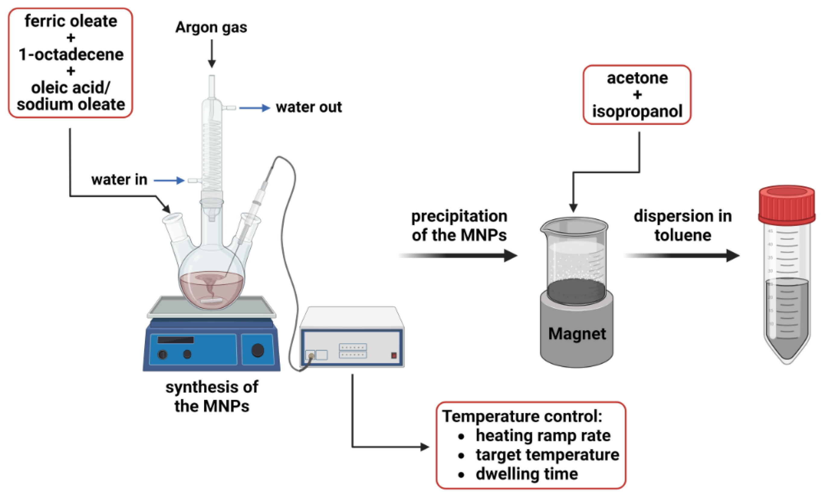
2.2.2. Magnetic Nanoparticles Synthesis

Hydrophobic monodispersed magnetic nanoparticles were synthesized through thermal decomposition. The synthesis of the MNPs relies on reducing the iron oleate at high temperatures. Iron oleate (1.6 g, 1.78 mmol), oleic acid (600 µL, 1.78 mmol) and 1-octadecene (25 mL, 1.9 mmol) were added to a two-necked round bottom flask (RBF), which was then connected to a reflux-condenser and a thermocouple. The mixture was magnetically stirred under Argon atmosphere while the temperature was gradually increased to 320 °C. The inert (Argon) atmosphere from the synthesis process was used to avoid possible oxygen contamination and to reduce the particles’ size [16]. The heating ramp rate of the process was 3 °C/min. After the first hour of the reaction, the mixture changed colour from dark orange to black, indicating the nucleation of crystallites. The reaction mixture was kept at the target temperature of 320 °C for 45 min, which had the purpose of growing the nanoparticles. Next, the RBF was cooled down to room temperature. Next, 25 mL of hexane was added to the mixture, transferred to a beaker, and placed on a magnet. Hexane is used to prevent flocculation and facilitate MNPs’ dispersion.
The magnetic nanoparticles were precipitated by adding a mixture of a 1:1 molar ratio of acetone and isopropanol. When all the particles were wholly precipitated, the supernatant was discarded entirely. Since magnetite oxidizes to maghemite while exposed to air [17], consequently, the obtained nanoparticles were washed thrice with acetone and then redispersed in 30 mL toluene. Figure 1 shows a generalized perspective of the synthesis strategy.
The presented method was used to synthesize spherical iron oxide nanoparticles. For the cubic nanoparticles, the same procedure was applied but with the following adjustments:
  • The precursors and the corresponding quantities were iron oleate (0.833 g, 0.96 mmol), sodium oleate (0.213 g, 0.7 mmol), and 1-octadecene (14 mL, 1.06 mmol);
  • The target temperature was 325 °C;
  • The heating ramp rate of the process was 2.8 °C/min.

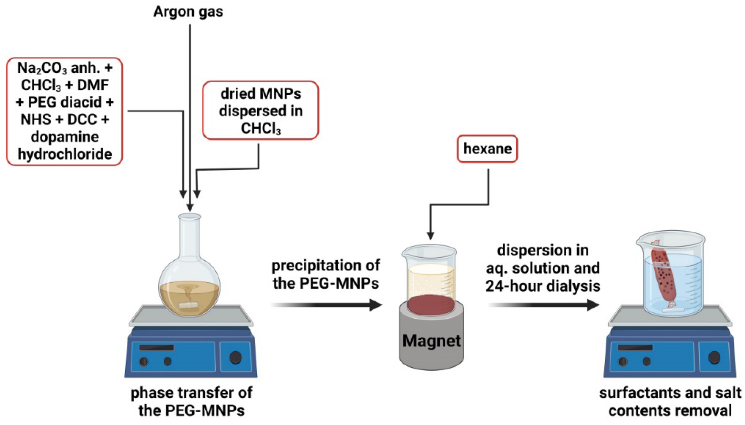
2.2.3. Phase Transfer of the Magnetic Nanoparticles

The protocol for the phase transfer process corresponds to the work performed by [18]. In a 25 mL RBF, anhydrous Na2CO3 (10 mg, 0.094 mmol) was dissolved in CHCl3 (2 mL, 0.025 mmol) and DMF (1 mL, 0.013 mmol), after which PEG diacid (20 mg, 0.007 mmol), NHS (2 mg, 0.017 mmol), DCC (3 mg, 0.015 mmol), and dopamine hydrochloride (1.27 mg, 0.0083 mmol) were added to the mixture and magnetically stirred for two hours at room temperature. After that, 5 mg of dried MNPs dispersed in 1 mL CHCl3 were added slowly. The solution was left overnight while stirring under an inert atmosphere. The solution was transferred to a beaker, where the PEG-MNPs were precipitated with hexane and magnetically separated. The functionalized nanoparticles were left to dry for at least 24 h and then redispersed in a 5 mL aqueous phase (MQ Water). Dispersed nanoparticles were left for 24 h dialysis to certify the removal of surfactants or salt contents. While in the dialysis bag, the water was changed every two hours thrice. Figure 2 shows a generalized perspective of the phase transfer process.

2.3. Characterization

The shape and core diameter of the magnetic nanoparticles were examined using a bright field scanning transmission electron microscope (BFSTEM; Hitachi S-5500, Hitachi High-Tech Corporation, Tokyo, Japan). The samples were prepared by drying a small amount of the diluted MNP solution on carbon-coated copper grids. The particles’ hydrodynamic size and zeta potential were measured using an Anton Paar Litesizer (Anton Paar GmbH, Graz, Austria) and a Malvern Zetasizer Nano-ZS device (Malvern Panalytical Ltd., Malvern, UK). Before the measurements, the samples were diluted to a 0.1 mg/mL concentration. For the PEG-MNP, disposable cuvettes (for size measurements) and Omega cuvettes (for zeta potential measurements) were employed, whereas glass cuvettes were used for the bare nanoparticles. An Alternating Gradient Magnetometer (AGM), Princeton PMC Model 2900 (Lake Shore Cryotronics, Inc., Westerville, OH 43082, USA), and a vibrating sample magnetometer (VSM 880-ADE Technologies, Westwood, MA, USA) were used to measure the MNPs’ saturation magnetization (Ms) curves. The instrument’s sensitivity was adjusted to 500 memu, with a 104 Oe maximum magnetic field applied. The average duration was 300 ms, and the applied field increment was 100 Oe. A rotating rheometer (Anton Paar MCR 300 Physica, Anton Paar GmbH, Graz, Austria) with a 20 mm diameter plate–plate magnetorheological cell (MRD 170/1T-SN80730989) was used to test the magneto-viscous properties of the pegylated nanoparticles at 25 °C in both the presence and absence of a magnetic field.

3. Results

3.1. MNPs’ Synthesis and Morphology
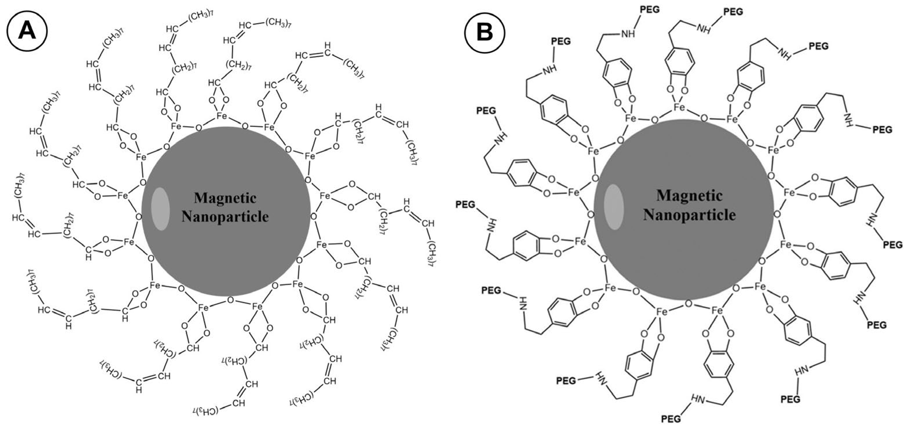
The final shape of the magnetic nanoparticles is influenced by the solution content, temperature, pressure, and synthesis technique [19].
Magnetic nanoparticles synthesized using the thermal decomposition method can have a consistent particle dispersion [20]. This technique’s key benefit is that it produces monodisperse, small-sized, and highly crystalline magnetic nanoparticles [21].
Iron (III)-oleate was thermally decomposed to produce the nanoparticles, using oleic acid as a stabilizing ligand.
The purpose of precipitating the nanoparticles with acetone, followed by rigorous stirring, was to remove the leftover oleate precursor and surplus oleic acid. After discharging the supernatant, the nanoparticles were redispersed in toluene and stored at 4 °C. Table 1 provides an overview of the synthesis procedures for cubic- and spherical-shaped nanoparticles.

3.1.1. Oleic Acid

The MNPs’ coating affects stability, upcoming functionalization, or hydrophobic or hydrophilic behaviour [22].
Oleic acid is widely used as a capping agent in ferrite nanoparticle synthesis. It can form a dense protective monolayer film, strongly bonded to the surface of the particle. This capping agent leads to the formation of highly uniform and monodispersed particles [23,24]. However, coating MNPs with OA makes them dispersible only in organic solvents, consequently limiting their use for biomedical applications [25]. Therefore, this hydrophobic coating must be replaced with a hydrophilic coating for biomedical applications in aqueous environments.
Oleic acid was employed as the coating surfactant in our work because it can stop particle oxidation and aggregation. The MNPs aggregate and become unstable in solution if not coated with surfactants [26].
Paper [26] shows that the strong bond between oleic acid and the surface of the nanoparticles is caused by the terminal carboxylic group, with a negative charge from the acid’s chain interacting with the positive charge from the surface (Figure 3A). Additionally, the cis-double bond from the oleic acid chain generates a kink required for the MNP to stabilize well [27]. In the phase transfer process mentioned in Section 2.2.2, when bonding the PEG to the surface of the magnetic nanoparticle, the following interactions took place [28]: first, the dopamine was linked to one of the carboxylic groups of the PEG diacid through the NHS reagent, which is used to trigger the reaction. Second, the dopamine-linked PEG bound covalently to the surface of the nanoparticle due to dopamine’s high affinity to iron oxide. In the process, the oleate was displaced from nanoparticle’s surface in the organic solution of CHCl3/DMF, which enabled the phase transfer of the PEG-covered MNP to aqueous solution (Figure 3B).

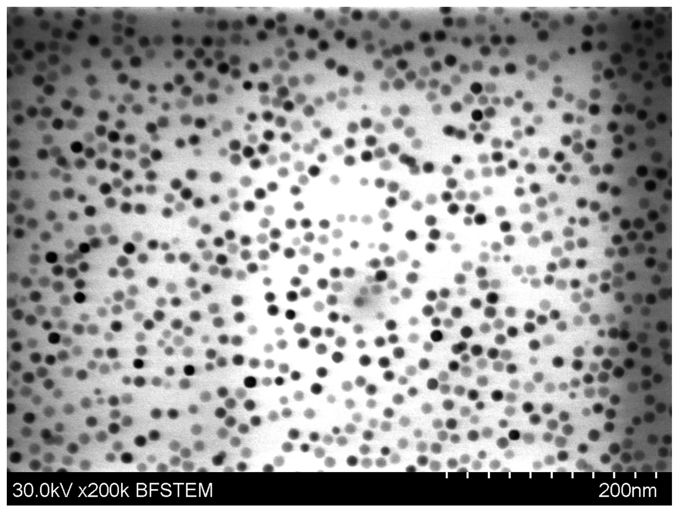
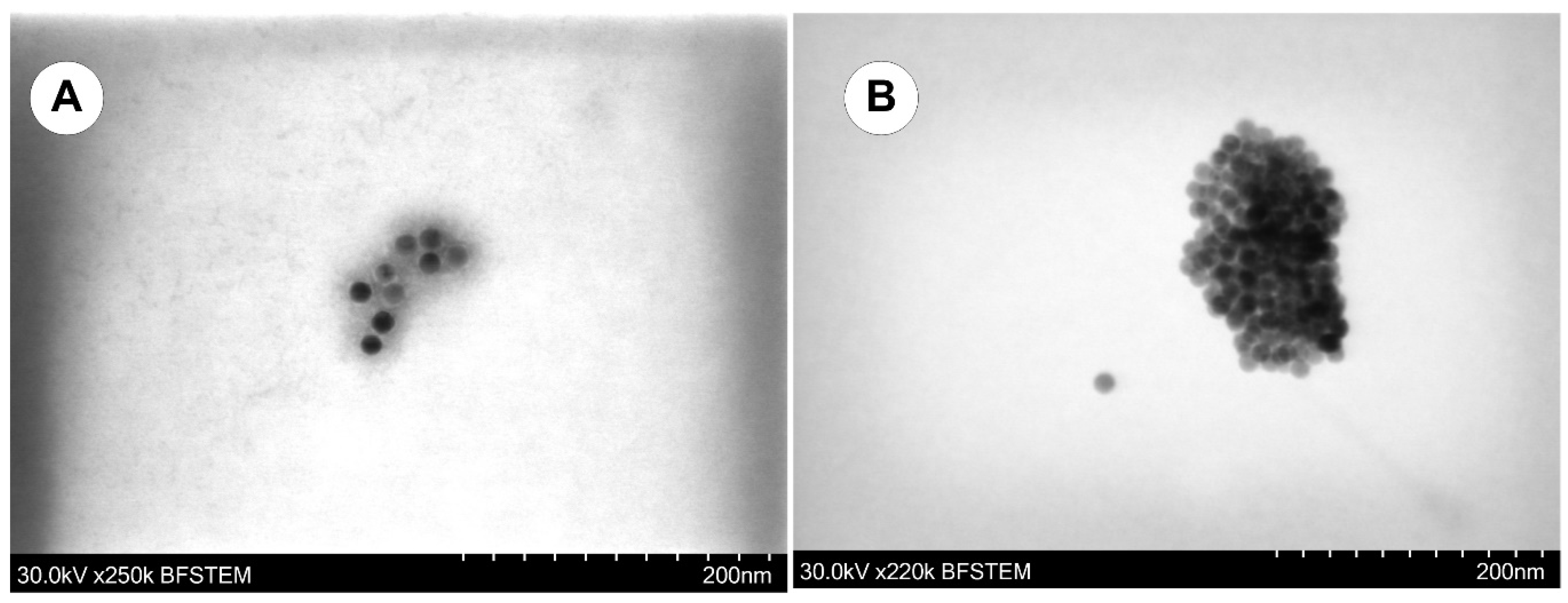
3.1.2. MNPs’ Morphology

Bright-field scanning transmission electron microscopy (BFSTEM; Hitachi S-5500) was used to conduct a primary analysis of the size and form of both spherical (Figure 4) and cubic (Figure 5) individual core particles. The diameters of 300 cores were extracted from the TEM images using the program ImageJ [https://imagej.nih.gov/ij/ (accessed on 10 February 2023)] to produce a frequency distribution of the MNPs’ core diameter. The mean core sizes of the spherical and cubic shapes were, respectively, 10.2 nm (Figure 6A) and 15.6 nm (Figure 6C), according to the fit of the log-normal [29] distribution of the core diameters.
Positive skewness can be seen in the diameter distribution for both spherical and cubic IONPs, with a mean diameter of 10 nm for spherical IONPs (Figure 6A) and a mean edge length of 15.5 nm for cubic IONPs (Figure 6C).

3.1.3. MNPs’ Colloidal Stability

DLS measurements were used to confirm the different MNPs’ aqueous colloidal stability. In addition, a Zetasizer Nano series was used to assess the size distribution and surface charge of the nanoparticles at room temperature of 25 °C using dynamic light scattering (DLS) and zeta potential (Malvern Instruments, Malvern, UK).
The effectiveness of hydrodynamic diameter measurements was utilized to test the colloidal stability of IONPs [30]. Aggregation and larger effective hydrodynamic diameters indicate a decrease in colloidal stability. The zeta descriptor determines NP’s colloidal stability, quantifying the electrostatic potential between the NP’s shear plane and the solvent. Charge differences over (>±10 mV) cause higher interparticle repulsion.
A Malvern Instrument Zetasizer Nano series with a He-Ne laser (λ = 633 nm, max 5 mW) and a scattering angle of 173° was used for all DLS experiments. A quartz cuvette measuring the dimensions of 10 mm by 10 mm was filled with 1 mL of particle suspension for each measurement.
It was discovered that the hydrodynamic diameter of the original IONPs in toluene before polymer coating was around 20 ± 0.4 nm for spherical MNPs (Figure 6B) and 25 ± 5.7 nm for cubic MNPs (Figure 6D), with polydispersity index values less than 0.14 for spherical MNPs and, respectively, 0.11 for cubic MNPs (Table 2).
Moreover, a Zetasizer Nano Series device (Malvern Instruments Ltd., Malvern, UK) was used to measure the coated IONPs’ zeta potential (ZP). ZP values typically fall within the −100 to +100 mV range. According to [31], colloidal stability can be predicted by the magnitude of ZP. Lower dispersions ZP values (where attraction defeats repulsion) will cause aggregation, coagulation, or flocculation due to van der Waals interparticle attraction [31]. In contrast, the ZP of MNPs with values of −25 mV or + 25 mV usually have a high degree of stability (which prevents the particles from aggregating due to electric repulsion) [31].
Table 2 shows that the cubic MNPs have a ZP of −23.9 mV rather than the −14 mV found in spherical shaped MNPs, indicating that the cubic MNPs are more stable. The samples were homogenized for 10 min in an ultrasonic bath before each measurement, followed by 2 min of repose.

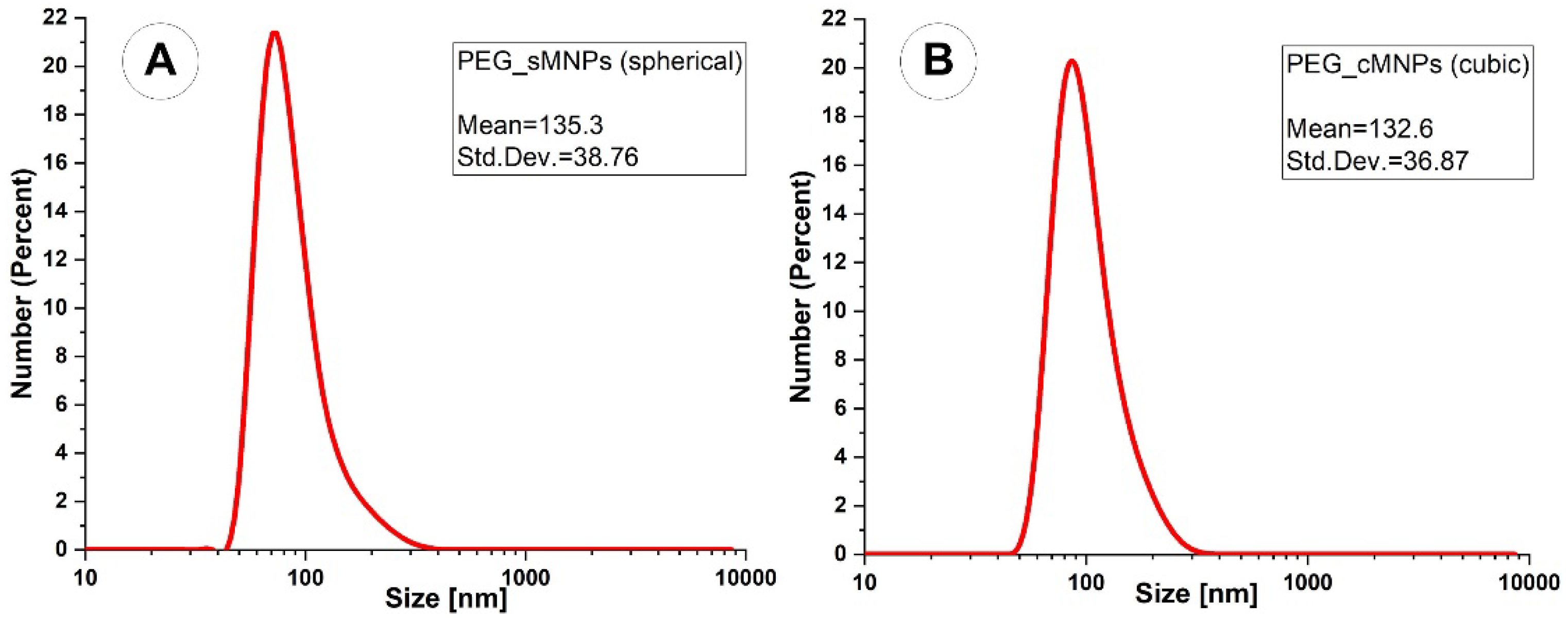
3.2. Synthesis of the PEG-coated IONPs

If a biomedical use is envisioned, addressing the colloidal stability of the MNPs under physiological settings is crucial. These nanoparticle aggregates would represent an immediate hazard to health if the prepared nanoparticles were administered topically to a living being. Additionally, unprotected inorganic nanoparticles are vulnerable to opsonization, an innate immune system defensive mechanism in which specific serum proteins bind to the particle surface and trigger phagocytosis. As a result, it is essential to swap out the hydrophobic protective shell for hydrophilic ligands, which provide excellent colloidal stability in an aqueous environment and shield serum proteins from opsonizing the material under physiological circumstances.
It has been demonstrated that surface alterations or polymer coatings enhance the stability, dispersity, and biocompatibility of MNPs [32].
To stop NP aggregation or agglomeration, polyethene glycol (PEGylation) is frequently used [33]. Although it often slows down the process, the PEGylation of NPs does not ensure the eradication of NP aggregation or agglomeration. In addition, even PEGylated NPs have the potential to self-associate over time, either due to the PEG layer degrading or the introduction of instability factors into the colloidal system [34]. Therefore, PEGylated and non-PEGylated samples should be concerned with the distribution of these self-associated structures.
Before the polymer coating, it was discovered that the original spherical IONPs in toluene had a hydrodynamic diameter of 19.8 nm. Following the polymer coating, the equivalent hydrodynamic diameters for the PEG-coated IONPs were 135.3 ± 38.8 nm for spherical particles and 132.6 ± 36.9 nm for cubic particles; see Table 3 and Figure 7. Note that we used a 220 nm filter to filter the particles because the hydrodynamic particle size after PEG coating was more than 250 nm (the literature states that the size is recommended to be lower than 250 to 300 nm). For instance, the initial hydrodynamic diameter of coated cubic IONPs was between 260 and 320 nm, whereas coated spherically shaped particles ranged between 300 and 900 nm. Afterwards, in Section 4.1.2, this outcome will be described.
Zeta potential studies revealed that the average zeta potential for the cubic nanoparticles was −28.3 mV. For the spherical nanoparticles, it was −26.9 mV, indicating better biocompatibility and successful surface passivation for both coated IONPs.

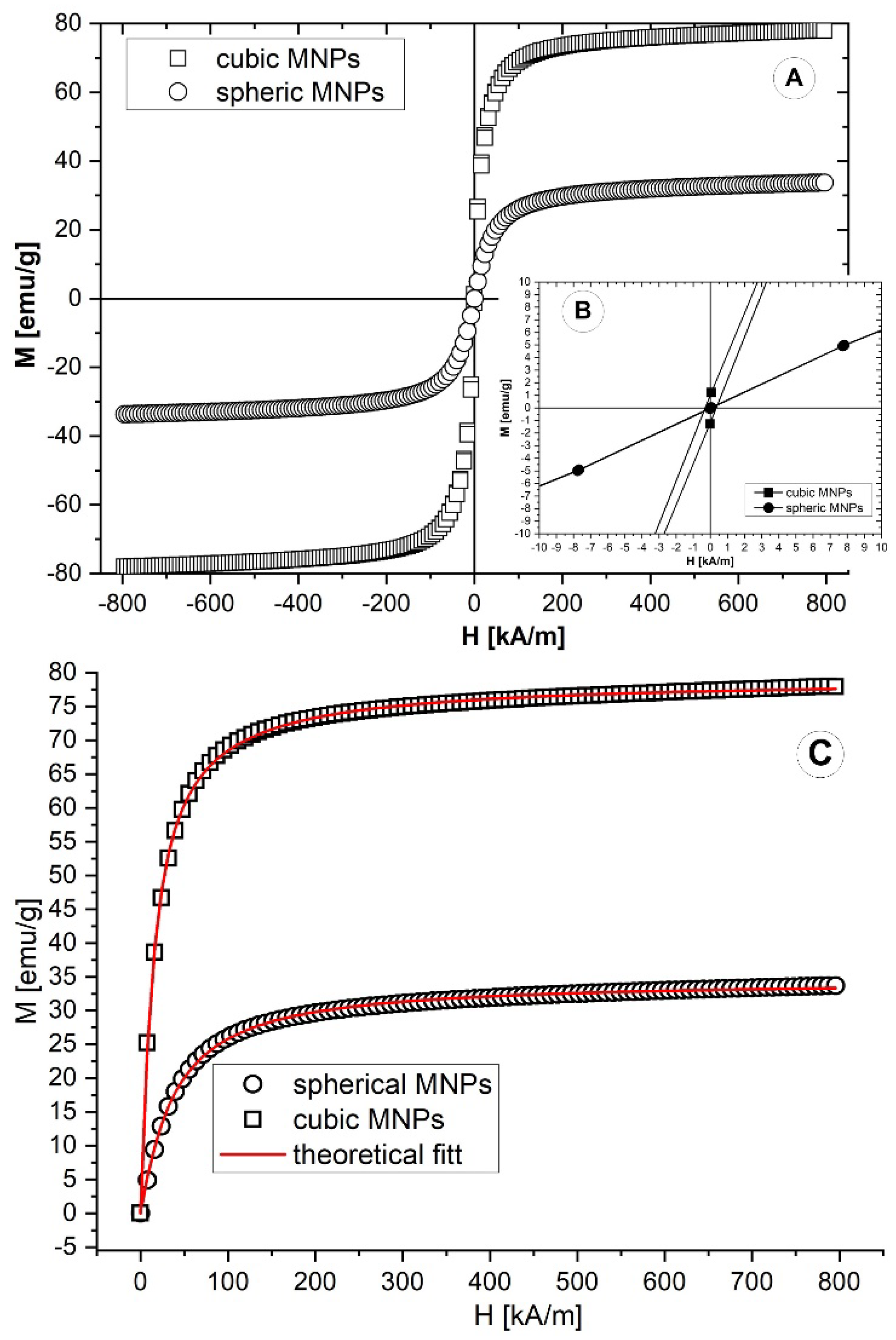
3.3. IONPs’ Magnetic Property

The DC magnetization of the two IONPs under investigation was measured at room temperature using a magnetometer (Alternating Gradient Magnetometer (AGM), Princeton PMC Model 2900, Westerville, OH, USA; VSM 880-ADE Technologies, Westwood, MA, USA) with a field range of 0 kA/m to 900 kA/m.
The hysteresis (M-H) loops for both samples are shown in Figure 8A,B at 294 K. The magnetic characteristics of the IONPs are summarized in Table 4. The spherical IONPs have zero remanence, while the cubic IONPs have 1.1 emu/g remanent magnetization due to their shape anisotropy. The reduced values of the squareness ratio, Mr/Ms, indicate that the particles are superparamagnetic and that their magnetization is dominated by thermal fluctuations [35]. The saturation magnetization (Ms) at 900 kA/m is 34 emu/g for spheres and 78 emu/g for cubes. The saturation magnetization of both IONPs is lower than the magnetite domain magnetization, 92 emu/g [36], due to the surfactant and the dead surface magnetic layer [37]. The latter is confirmed by the discrepancy between SPIONs’ TEM and magnetic diameter (see Table 2). The SPIONs’ magnetic diameter was determined by fitting the first magnetization curves (Figure 8C—symbols) with a theoretical model for highly concentrated magnetic colloids [38,39].
Table 4 compares the saturation magnetization of the MNPs synthesized in this paper and the different values presented in the literature.

3.4. Rheological Properties of the IONP’s Aqueous Dispersion

3.4.1. Model Suspension Preparation and Characteristics

Glycerol–water solutions with a density (1060 kg/m3) identical to that of blood served as the carrier fluid (CF) in our research [8,9]. These solutions were created by combining calculated weights of glycerol and distilled water. This CF facilitated the experimental studies by adequately reproducing the rheological behaviour of the fluid flow at the implanted stent site. In addition, the model suspension of magnetic carriers used in experiments was made by mixing PEG-coated IONPs with a carrier fluid (CF) at a mass concentration of 0.15 per cent.
Figure 9 displays the comparison of the blood sample [8] (obtained from a 38-year-old female volunteer in good health), the model suspension’s viscosity curve (CF + 0.15% PEG_IONPs) at T = 25 °C, and the findings reported in the literature [41].
The generated magnitude of the applied field determines the amount of change in the model suspension. The PEG-coated IONPs utilized in the model suspensions demonstrated the necessary responsiveness to a magnetic field’s action, as seen in Figure 10. When a magnet is placed next to the bottle, the magnetic IONPs are drawn to it (Figure 10A,B), but the functionalized IONPs can quickly disperse in the suspensions when there is no magnetic field.

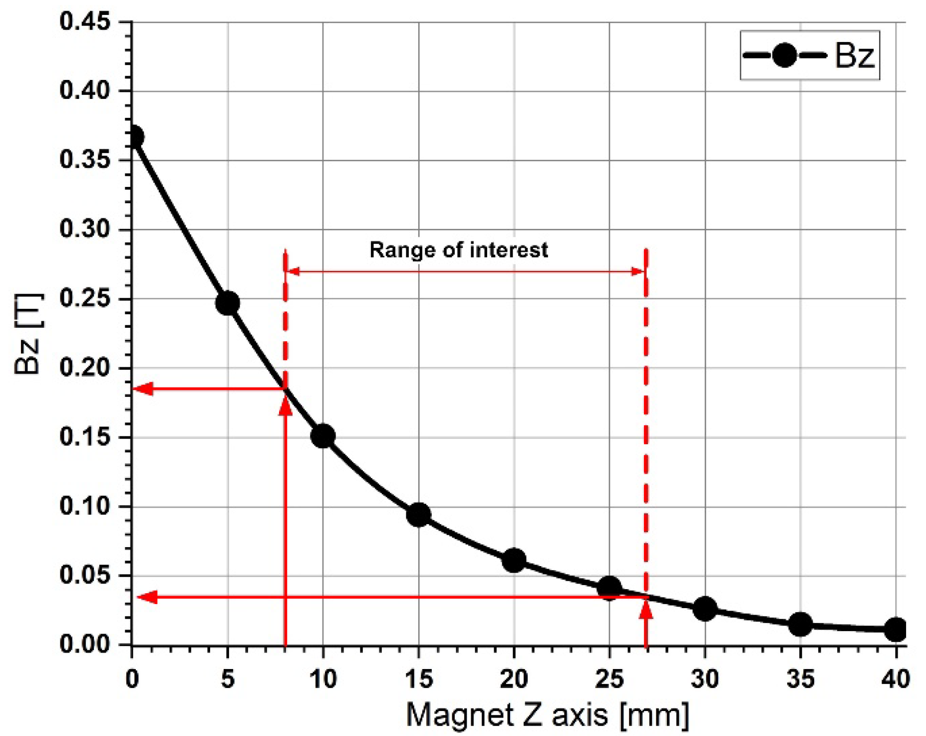
3.4.2. Magnetic Field

This paper aims to examine the potential of manufactured nanoparticles in drug-targeting applications; hence, it is crucial to understand the rheological behaviour of both simple and functionalized (with PEG) particles in the presence or absence of an external magnetic field that influences them.
Because the magnetic field’s force must outweigh the hydrodynamic (drag) force and the shear effects produced by the running blood cells, the magnetic capture of nanoparticles at flow conditions typical of larger arteries may be more challenging. The magnetic field gradients and the flow dynamics consequently govern the behaviour of magnetic particles in circulation and the effectiveness of their aggregation in addition to the nanoparticle features [43].
External magnetic stimuli can affect magnetic suspensions and cause them to react. Whether a static magnetic field is homogenous or inhomogeneous affects how an object reacts [42]. If the field is homogenous (uniform in direction and amplitude), the material will undergo microstructural changes that will significantly affect its rheological and macroscopic features, such as the agglomeration of the particles into chains or columns [44].
In this paper, we used a Neodymium-type 52 magnet (NdFeB52) to produce the magnetic field with a maximum energy product (BxH) of 52 MGOe. In addition, we investigated the magnetic particle targeting in our research for magnetic fields generated between 0.18 T and 0.04 T, which corresponded to the magnet position between 8 mm and 27 mm from the magnet surface (along with the magnet z-axis—Figure 11).

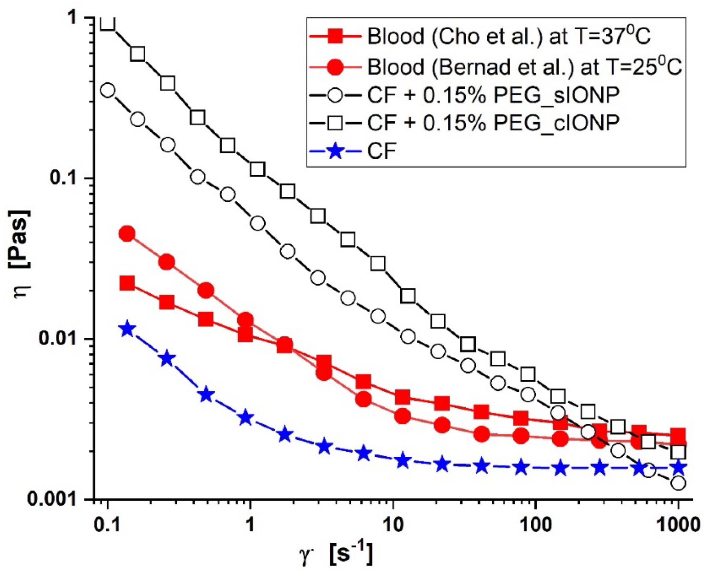
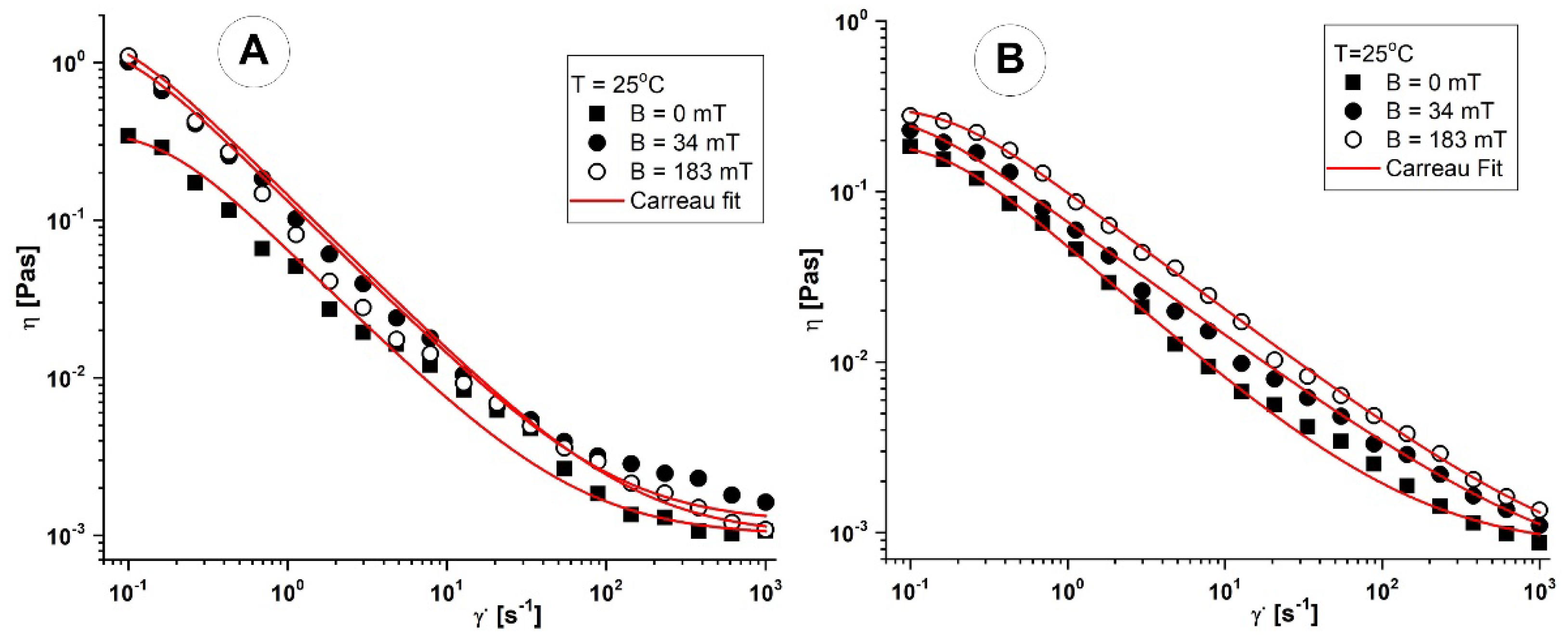
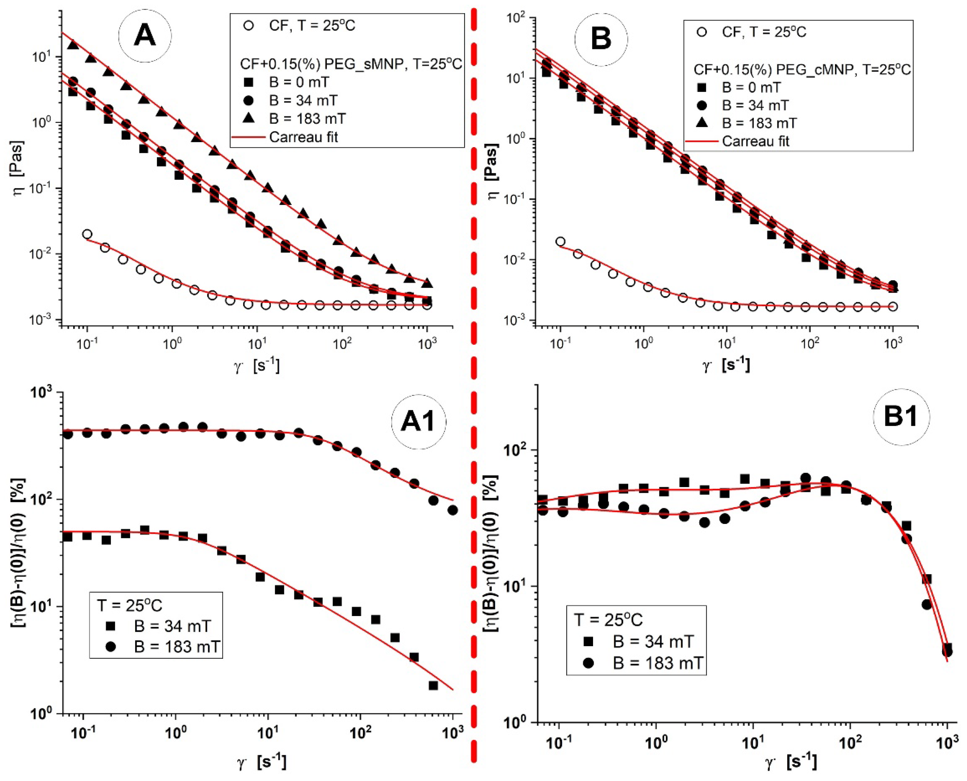
3.4.3. Viscosity Curves of the Spherical and Cubic MNPs Aqueous dispersions

In both the presence and absence of an external magnetic field, MNPs particle suspensions’ steady-state shear flow behaviour was assessed. Because shear flow is the predominant flow element in most applications, the study was restricted to it. The viscosity curves were used to define the behaviour of the MNPs particle suspensions. The shear rate regime was selected to encompass the range of shear rates necessary for the drug targeting applications.
Parallel plate geometry was used to apply steady shear strain to the suspensions. A shear rate ramp-up in the 0.1–1000 s−1 range was used to obtain the viscosity curves of apparent viscosity (η) vs. shear rate ( γ ˙ ). The magnetorheological (MR) accessory produced a perpendicular external magnetic field to the shear flow. The temperature for all rheological testing was 25.0 °C. For these tests, the materials were placed into the rheometer immediately following ultrasonic homogenization (for all the samples, the applied energy was 2000 J with 0.5 cycles and an amplitude of 80% in three consecutive steps), and we used freshly made suspensions for these tests.
Figure 12 depicts the variations in the shear viscosity of the cubic and spherical IONPs mixture suspensions as a function of shear rate for three distinct magnetic field intensities ranging from 0 to 183 mT. Stepwise, as the magnetic field intensity rose, the shear viscosity increased. However, the shear viscosity behaviour of the MNP suspensions of both kinds was comparable under each magnetic field. In addition, shear thinning behaviour was seen for both particle suspensions in the low shear rate area (0.1 s−1 to 1 s−1), demonstrating that the structures of the dispersed magnetic particles formed under the external magnetic field persisted until the shear rate reached 400 s−1.
The Carreau model (Equation (1)) and the data from the η = f( γ ˙ ) were associated [45]:
η ( γ ˙ ) = η + ( η o η ) 1 + ( C γ ˙ ) 2 p ,
in which C [s] represents the Carreau constant (the value of the slope of the viscosity curve in the log–log scale at high values of the shear rate γ ˙ ), p [−] is the Carreau exponent, η0 is the viscosity at infinitely low shear rates, and η [Pas] is viscosity at infinitely high shear rates.

4. Discussion

4.1. Perspective of Biomedical Applications for the Cubic and Spherical Shape MNPs

The functionalized MNPs enter the bloodstream by intravenous injection and pass through the cardiovascular system. At this stage, protein adsorption might cause a considerable change in the surface chemistry, highlighting the need for effective shielding of the MNPs [46].
The injected MNPs will gradually diffuse outside the blood vessels and into the surrounding extracellular matrix (ECM). As a result, the local MNPs concentration in the blood is relatively high after injection, proportionate to the extravascular area. In this condition, some NPs are absorbed by tissue cells once they reach the extravascular space. In contrast, others are maintained in the interstitial fluid and eventually enter the lymphatic system [47].
It has been demonstrated that surface alterations, particularly polymer coatings, enhance the biocompatibility, dispersity, and stability of MNPs [32].
The steric repulsion prevents particle aggregation after the PEG surface coating since the nanoparticles are always expected to stay enclosed by their protective ligand shell.
The manufactured spherical and cubic PEG-coated MNPs were dispersed in an aqueous carrier (blood analogue fluid) to form the model suspensions, which precisely reflected the rheological behaviour of the fluid flow during the magnetic drug targeting application.
The model suspension results from the carrier fluid (CF) combination and 0.15 per cent mass concentration of the PEG-coated MNPs and the preparation of the blood analogue fluid (the carrier fluid) were presented in our previous chapter.

4.1.1. Rheological Aspects of the PEG-Coated Cubic and Spherical IONPs Suspension from the Application Point of View

External magnetic stimuli have an impact on magnetic suspensions and can control them. For example, suppose the external magnetic field is homogenous (uniform in direction and strength). In that case, the material will undergo microstructural changes (such as the aggregation of the particles into chains), which will significantly affect the rheological characteristics of the suspensions.
So, from the perspective of magnetic targeting, altering the rheological behaviour of the injected therapeutical suspension can significantly impact the targeting processes’ effectiveness. Therefore, in the following chapter, we will investigate the rheological behaviour of the model suspension both with and without an external magnetic field.
As mentioned in the previous chapter, a coil integrated into the plate–plate magnetorheological cell and set perpendicular to the plane of the plates created a homogeneous magnetic field that was used to measure the viscosity curves of the two model suspensions both with and without it.
First, we discuss how viscosity changes with the shear rate when the magnetic field strength is zero. Figure 13A,B display the logarithmically scaled viscosity curves of the suspensions with PEG-coated spherical and cubic magnetite that are not in a magnetic field. The two PEG-coated MNP suspensions behaved similarly and did not significantly differ. The aggregation of the particles caused the shear thinning of both samples (reduction in viscosity with increasing shear rate). When the shear rate was low, the particles attracted one another and stayed together in the suspension’s volume.
The Van der Waals attraction force between the coated MNPs drives the agglomeration without a magnetic field. The higher viscosity (η ≈ 1–10 Pas) of the MNPs suspensions at low shear is caused by this network of agglomerated particles (both for PEG-coated spherical and cubic MNPs) (Figure 13A,B).
Shear forces destroy the particle network as the suspension starts to flow and the shear rate rises. As a result, the size of the agglomerates continues to decrease with increasing γ ˙ , which lowers the viscosity. The viscosity may attain a constant value at high shear rates, at which point shear forces alone cannot decrease the size of the clusters.
All suspensions showed altered flow behaviour in a magnetic field. Figure 13A,B compare the viscosity curves for zero magnetic fields and two different field strengths. Both suspensions displayed the previously noted shear-thinning property in a magnetic field.
The values obtained for the fit parameters are listed in Table 5. As expected, in the presence of the magnetic field, the values of the fit parameters η0, C, and p increase with the intensification of the field.
Additionally, to better compare the characteristics of the two nanoparticles under different conditions, Table 6 summarize the rheological properties of the MNPs under an applied magnetic field.
The single-domain IONPs provide the particle aggregates with a persistent magnetic dipole moment. The difference in magnetic permeability between the particles and the dispersion medium also induces a magnetic dipole moment in an external magnetic field. In a magnetic field, the attraction force is amplified due to the appearance of dipole–dipole interactions, which causes chain-like structures to develop parallel to the field. The suspensions in a magnetic field are more viscous due to this attractive structure perpendicular to the shear flow.
When the applied shear rate rises, the nanoparticles organize themselves in the shearing direction. Additionally, as the shear rate increases, aggregate formations with a chain-like structure are destroyed, which causes the viscosity to decrease.
The magneto-viscous effect (MVE) is the term used to describe the relative increase in viscosity caused by a magnetic field. This effect is most pronounced when using weak magnetic fields; as the magnetic field increases, it usually decreases.
It can be observed in Figure 13(A1,B1) that the effect of MVE on the range of low shear rates is almost independent of the shear rate but significantly decreases at high speeds. At this point, the particle agglomerations are destroyed.
The main finding of this study is that, compared to cubic IONPs, spherical IONPs exhibit a significantly higher shift in flow behaviour due to the external magnetic field (Figure 13). This finding is crucial for magnetic targeting because it can impact the injectability and workability of the active suspension [48] when changes in the rheological properties of the model suspensions occur when an external magnetic field is present.

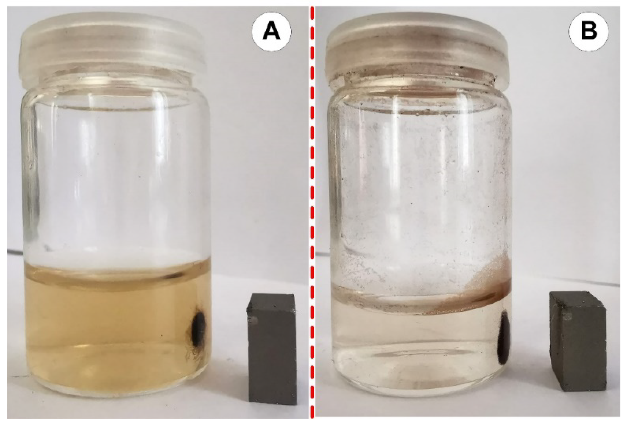
4.1.2. PEG-Coated IONPs Sedimentation

This investigation also looked at the sedimentation of the PEG-coated nanoclusters (Figure 14). The sedimentation was recorded throughout 24 h as a function of time. The current findings demonstrate that the PEG-coated IONPs dispersion was stable enough to be used in the experimental study, given that the injection period of the model suspension used for experimental investigations in our prior work [8] was roughly 30 s.
Moreover, as can be seen from Figure 14, the cubic nanoparticles are more stable compared to the spherical ones. This could be due to the zeta potential value, which is two times larger for the cubic nanoparticles (Table 2), and which is known to influence the stability of nanoparticles in suspension [49]. A large positive or negative value for zeta potential indicates good stability as a result of the electrostatic repulsion of the particles. On the other hand, small values for zeta potential may lead to particle aggregation and flocculation. This is the result of the van der Waals attractive forces that act upon the particles [50].

4.1.3. PEG-Coated IONPs Aggregation

Monitoring the particles’ colloidal stability is another crucial application of DLS [51]. Thus, it is essential to employ DLS to monitor the aggregation kinetic of MNPs to give precise input regarding the duration of this process [52].
In our investigations, the IONPs particles considerably agglomerate during storage in the suspensions. Therefore, the practical solutions were bath sonicated before each experiment to disperse these agglomerates and achieve a consistent initial particle size.
In this chapter, we assessed how the two synthesized IONPs aggregated. The increase in hydrodynamic radius caused by particle–particle aggregation was measured using DLS.
Several published sources detailing nanoparticle synthesis mention cluster sizes far more prominent than the initial size [53].
Following synthesis, the measured hydrodynamic radius for spherical and cubic MNPs was 19.8 nm and 25 nm, respectively, 2 and 1.7 times bigger than the individual particle radius reported by TEM investigations. In addition, the PEG coating of the particles raised their measured radius by ≈13 times, to 153 nm for spherical IONPs and 154 nm for cubic IONPs, respectively.
Figure 15 shows that the IONPs particles strongly agglomerate after being stored in suspensions for 24 h. So, for an hour, we looked at the aggregation behaviour of both IONPs. As previously noted, the suspensions underwent a 10 min bath sonication procedure before the measurements began. When particle clusters more prominent than 200 nm in diameter are found during DLS measurements, accumulation is seen. It is essential to mention that the hydrodynamic diameter of both IONPs after PEGylation was around 135 nm (Figure 7).
These clusters, which most likely developed during the production of nanomaterials, were very hard to break apart by bath sonication or solution agitation (Figure 14 and Figure 15).
The aggregation behaviour depicted in Figure 15 aligns with earlier studies [54] looking at the aggregation of nanoparticles and nanoparticle clusters.
Figure 16 demonstrates that cubic-shaped IONPs are more stable throughout time. Hydrodynamic diameter measurements show a relatively slow variation of the DLS size distribution from 250 nm to 210 nm in the first 600 s. The PEG_cIONPs continue to have a diameter of about 210 nm after that. Contrarily, over the 60 min investigation period, the hydrodynamic diameter of PEG_sIONPs fluctuated significantly, from 855 nm to 460 nm.
The findings showed that most MNCs are soldered in substantial permanent clusters because of bridge contacts between polymer shells.
Another key finding relates to the sedimentation profile, specifically that PEG-coated IONPs with spherical shapes have a stronger tendency to sediment than those with cubic shapes, which are more stable.
Given that the average sizes of the IONPs particles (as determined by DLS) are 19.8 ± 0.4 nm for spherical IONPs and 24.7 ± 5.7 nm for cubic IONPs, it is assumed that the significant structures produced in the range of several hundred nanometres might result from the MVE’s characteristics discussed in the previous chapter.

5. Conclusions

Different synthesis routes lead to nanoparticles with contrasting dimensions, morphologies, and magnetization. Moreover, an essential aspect of synthesis is the type of reagent used and its concentration. In our work, MNPs were synthesized through thermal decomposition. Two morphologies were obtained, spherical and cubic, by altering the reagent, the heating ramp rate, and the target temperature. The spherical and cubic nanoparticles had similar dimensions but significant magnetization differences. Even though the particles had superparamagnetic characteristics, the magnetic saturation obtained for the cubic particles (d = 15 nm) was more than twice the one for the spherical particles (d = 10 nm), a difference that may be influenced by the 5 nm distinction between the two core types. Additionally, the low magnetic saturation values may result as an effect of the oleic acid coating, which is considered to influence the magnetic moment from the particle’s surface.
After PEGylation, the MNPs aggregated with 130–140 nm hydrodynamic diameters. These diameters exceeded the average values of 10–100 nm, which they must integrate to be used for medical purposes [55]. In addition, by investigating the particles for 24 h, it was observed that the cubic ones were more stable in suspension than the spherical ones.
In the case of using PEGylated nanoparticles for medical applications such as drug targeting, several aspects need to be known and understood, including the use of a suitable magnetic field and the rheological characteristics of the nanoparticles. Furthermore, the rheological behaviour of the active suspension containing PEG-coated IONPs should be as similar as possible to that of the blood. The rheological curves from this paper showed that the suspensions present a higher viscosity at lower shear rates for spherical and cubic PEG-coated nanoparticles when a magnetic field is applied. In the case of the PEG-coated spherical nanoparticles, when a higher magnetic field is used (B = 183 mT), the corresponding values show a sharp increase. In contrast, the PEG-coated cubic nanoparticles’ rheological curves are almost superimposed regardless of the magnetic field’s intensity. This suggests that the rheological behaviour of the PEG-coated cubic nanoparticles is weakly influenced if different values for the magnetic field are applied.
Considering all the above, both spherical and cubic magnetic nanoparticles can be suitable for medical applications due to their appropriate dimensions and high magnetization. However, a different method for coating the MNPs with PEG needs to be investigated to reduce the formation of aggregates and, consequently, the hydrodynamic diameters.

Author Contributions

Conceptualization, S.I.B. and M.-C.I.; methodology, S.I.B., M.-C.I. and V.S.; investigation, M.-C.I., S.B., N.B. and V.S.; resources, S.I.B. and S.B.; writing—original draft preparation, M.-C.I., S.I.B. and V.S.; writing—review and editing, M.-C.I. and S.I.B.; visualization, M.-C.I., S.B. and N.B.; supervision, S.I.B. and S.B. All authors have read and agreed to the published version of the manuscript.

Funding

This research received no external funding.

Institutional Review Board Statement

Not applicable.

Informed Consent Statement

Not applicable.

Data Availability Statement

Not applicable.

Acknowledgments

For S.I. Bernad, this work was supported by the RA-TB/CFATR/LHC multiannual research program 2023–2024. For V. Socoliuc, this work was supported partially by the RA-TB/CFATR/LMF multiannual research program 2023–2024 and by a grant from the Ministry of Research, Innovation and Digitization, CNCS/CCCDI-UEFISCDI, project number PN-III-P2-2.1-PED-2021-2049, within PNCDI III. For M.C. Ioncica, this work was supported partially by a grant from the Ministry of Research, Innovation and Digitization, CNCS/CCCDI-UEFISCDI, project number PN-III-P2-2.1-PED-2021-2049, within PNCDI III, and partially by the Twinning project SIRAMM (Structural Integrity and Reliability of Advanced Materials Obtained through Additive Manufacturing), European Union Horizon 2020 H2020-WIDESPREAD-2018-03, grant agreement No. 857124. Contribution: All the synthesis and functionalization experiments, starting from the iron oxide NPs, their functionalization and surface modification, were performed at the Norwegian University of Science and Technology, Norway. TEM investigations were conducted at the Norwegian University of Science and Technology, Norway. The Research Council of Norway is acknowledged for the support to the Norwegian Micro- and Nano-Fabrication Facility, NorFab, project number 295864. The magnetic characterization studies were carried out at the Norwegian University of Science and Technology, Norway, and the Research Centre for Engineering of Systems with Complex Fluids, Politehnica University Timisoara, Romania. DLS characterization studies for spherical nanoparticles were carried out at the Norwegian University of Science and Technology, Norway, and for cubic nanoparticles at the Research Centre for Engineering of Systems with Complex Fluids, Politehnica University Timisoara, Romania. All the rheological investigations were carried out at the Research Centre for Engineering of Systems with Complex Fluids, Politehnica University Timisoara, Romania.

Conflicts of Interest

The authors declare no conflict of interest.

References

  1. Mccarthy, J.; Weissleder, R. Multifunctional Magnetic Nanoparticles for Targeted Imaging and Therapy. Adv. Drug Deliv. Rev. 2008, 60, 1241–1251. [Google Scholar] [CrossRef] [Green Version]
  2. Masood, F. Polymeric Nanoparticles for Targeted Drug Delivery System for Cancer Therapy. Mater. Sci. Eng. C 2016, 60, 569–578. [Google Scholar] [CrossRef] [PubMed]
  3. Cherkasov, V.R.; Mochalova, E.N.; Babenyshev, A.V.; Vasilyeva, A.V.; Nikitin, P.I.; Nikitin, M.P. Nanoparticle Beacons: Supersensitive Smart Materials with On/Off-Switchable Affinity to Biomedical Targets. ACS Nano 2020, 14, 1792–1803. [Google Scholar] [CrossRef] [PubMed]
  4. Shabatina, T.I.; Vernaya, O.I.; Shabatin, V.P.; Melnikov, M.Y. Magnetic Nanoparticles for Biomedical Purposes: Modern Trends and Prospects. Magnetochemistry 2020, 6, 30. [Google Scholar] [CrossRef]
  5. Nguyen, L.T.H.; Muktabar, A.; Tang, J.; Dravid, V.P.; Thaxton, C.S.; Venkatraman, S.; Ng, K.W. Engineered Nanoparticles for the Detection, Treatment and Prevention of Atherosclerosis: How Close Are We? Drug Discov. Today 2017, 22, 1438–1446. [Google Scholar] [CrossRef] [PubMed]
  6. George, T.A.; Hsu, C.-C.; Meeson, A.; Lundy, D.J. Nanocarrier-Based Targeted Therapies for Myocardial Infarction. Pharmaceutics 2022, 14, 930. [Google Scholar] [CrossRef] [PubMed]
  7. Sun, S.-N.; Wei, C.; Zhu, Z.-Z.; Hou, Y.-L.; Venkatraman, S.S.; Xu, Z.-C. Magnetic Iron Oxide Nanoparticles: Synthesis and Surface Coating Techniques for Biomedical Applications. Chin. Phys. B 2014, 23, 037503. [Google Scholar] [CrossRef]
  8. Bernad, S.I.; Craciunescu, I.; Sandhu, G.S.; Dragomir-Daescu, D.; Tombacz, E.; Vekas, L.; Turcu, R. Fluid Targeted Delivery of Functionalized Magnetoresponsive Nanocomposite Particles to a Ferromagnetic Stent. J. Magn. Magn. Mater. 2021, 519, 167489. [Google Scholar] [CrossRef]
  9. Bernad, S.I.; Susan-Resiga, D.; Bernad, E. Hemodynamic Effects on Particle Targeting in the Arterial Bifurcation for Different Magnet Positions. Molecules 2019, 24, 2509. [Google Scholar] [CrossRef] [Green Version]
  10. Wu, L.; Wang, C.; Li, Y. Iron oxide nanoparticle targeting mechanism and its application in tumor magnetic resonance imaging and therapy. Nanomedicine 2022, 17, 1567–1583. [Google Scholar] [CrossRef]
  11. Nigam, S.; Barick, K.C.; Bahadur, D. Development of Citrate-Stabilized Fe3O4 Nanoparticles: Conjugation and Release of Doxorubicin for Therapeutic Applications. J. Magn. Magn. Mater. 2011, 323, 237–243. [Google Scholar] [CrossRef]
  12. Lin, J.-F.; Wu, J.; Zhu, J.; Mao, Z.; Said, A.H.; Leu, B.M.; Cheng, J.; Uwatoko, Y.; Jin, C.; Zhou, J. Abnormal Elastic and Vibrational Behaviors of Magnetite at High Pressures. Sci. Rep. 2014, 4, 6282. [Google Scholar] [CrossRef] [Green Version]
  13. Hui, C.; Shen, C.; Yang, T.; Bao, L.; Tian, J.; Ding, H.; Li, C.; Gao, H.-J. Large-Scale Fe3O4 Nanoparticles Soluble in Water Synthesized by a Facile Method. J. Phys. Chem. C 2008, 112, 11336–11339. [Google Scholar] [CrossRef]
  14. Ramírez-Cando, L.J.; De Simone, U.; Coccini, T. Toxicity Evaluation of Iron Oxide (Fe3O4) Nanoparticles on Human Neuroblastoma-Derived SH-SY5Y Cell Line. J. Nanosci. Nanotechnol. 2017, 17, 203–211. [Google Scholar] [CrossRef] [PubMed]
  15. Sharma, A.; Foppen, J.W.; Banerjee, A.; Sawssen, S.; Bachhar, N.; Peddis, D.; Bandyopadhyay, S. Magnetic Nanoparticles to Unique DNA Tracers: Effect of Functionalization on Physico-chemical Properties. Nanoscale Res. Lett. 2021, 16, 24. [Google Scholar] [CrossRef]
  16. Kim, D.K.; Zhang, Y.; Voit, W.; Rao, K.V.; Muhammed, M. Synthesis and Characterization of Surfactant-Coated Superparamagnetic Monodispersed Iron Oxide Nanoparticles. J. Magn. Magn. Mater. 2001, 225, 30–36. [Google Scholar] [CrossRef]
  17. Salazar-Alvarez, G.; Qin, J.; Šepelák, V.; Bergmann, I.; Vasilakaki, M.; Trohidou, K.N.; Ardisson, J.D.; Macedo, W.A.A.; Mikhaylova, M.; Muhammed, M.; et al. Cubic versus Spherical Magnetic Nanoparticles: The Role of Surface Anisotropy. J. Am. Chem. Soc. 2008, 130, 13234–13239. [Google Scholar] [CrossRef]
  18. McDonagh, B.H.; Staudinger, C.; Normile, P.S.; De Toro, J.A.; Bandyopadhyay, S.; Glomm, W.R.; Singh, G. New Insights into Controlling the Twin Structure of Magnetic Iron Oxide Nanoparticles. Appl. Mater. Today 2021, 24, 101084. [Google Scholar] [CrossRef]
  19. Wu, W.; Wu, Z.; Yu, T.; Jiang, C.; Kim, W.-S. Recent Progress on Magnetic Iron Oxide Nanoparticles: Synthesis, Surface Functional Strategies and Biomedical Applications. Sci. Technol. Adv. Mater. 2015, 16, 023501. [Google Scholar] [CrossRef]
  20. Unni, M.; Uhl, A.M.; Savliwala, S.; Savitzky, B.H.; Dhavalikar, R.; Garraud, N.; Arnold, D.P.; Kourkoutis, L.F.; Andrew, J.S.; Rinaldi, C. Thermal Decomposition Synthesis of Iron Oxide Nanoparticles with Diminished Magnetic Dead Layer by Controlled Addition of Oxygen. ACS Nano 2017, 11, 2284–2303. [Google Scholar] [CrossRef]
  21. Dadfar, S.M.; Roemhild, K.; Drude, N.I.; von Stillfried, S.; Knüchel, R.; Kiessling, F.; Lammers, T. Iron Oxide Nanoparticles: Diagnostic, Therapeutic and Theranostic Applications. Adv. Drug Deliv. Rev. 2019, 138, 302–325. [Google Scholar] [CrossRef]
  22. Bunge, A.; Leoștean, C.; Radu, T.; Tripon, S.C.; Borodi, G.; Turcu, R. Substituted Poly(Vinylphosphonate) Coatings of Magnetite Nanoparticles and Clusters. Magnetochemistry 2022, 8, 79. [Google Scholar] [CrossRef]
  23. Gelbrich, T.; Feyen, M.; Schmidt, A.M. Magnetic Thermoresponsive Core−Shell Nanoparticles. Macromolecules 2006, 39, 3469–3472. [Google Scholar] [CrossRef]
  24. Bronstein, L.M.; Huang, X.; Retrum, J.; Schmucker, A.; Pink, M.; Stein, B.D.; Dragnea, B. Influence of Iron Oleate Complex Structure on Iron Oxide Nanoparticle Formation. Chem. Mater. 2007, 19, 3624–3632. [Google Scholar] [CrossRef]
  25. Toster, J.; Kusumawardani, I.; Eroglu, E.; Iyer, K.S.; Rosei, F.; Raston, C.L. Superparamagnetic Imposed Diatom Frustules for the Effective Removal of Phosphates. Green Chem. 2014, 16, 82–85. [Google Scholar] [CrossRef]
  26. Soares, P.I.P.; Alves, A.M.R.; Pereira, L.C.J.; Coutinho, J.T.; Ferreira, I.M.M.; Novo, C.M.M.; Borges, J.P.M.R. Effects of Surfactants on the Magnetic Properties of Iron Oxide Colloids. J. Colloid Interface Sci. 2014, 419, 46–51. [Google Scholar] [CrossRef]
  27. Patil, R.M.; Shete, P.B.; Thorat, N.D.; Otari, S.V.; Barick, K.C.; Prasad, A.; Ningthoujam, R.S.; Tiwale, B.M.; Pawar, S.H. Non-Aqueous to Aqueous Phase Transfer of Oleic Acid Coated Iron Oxide Nanoparticles for Hyperthermia Application. RSC Adv. 2014, 4, 4515–4522. [Google Scholar] [CrossRef]
  28. Guerrini, L.; Alvarez-Puebla, R.; Pazos-Perez, N. Surface Modifications of Nanoparticles for Stability in Biological Fluids. Materials 2018, 11, 1154. [Google Scholar] [CrossRef] [Green Version]
  29. Cogoni, G.; Grosso, M.; Baratti, R.; Romagnoli, J.A. Time evolution of the PSD in crystallization operations: An analytical solution based on Ornstein-Uhlenbeck process. AIChE J. 2012, 58, 3731–3739. [Google Scholar] [CrossRef]
  30. Hühn, J.; Carrillo-Carrion, C.; Soliman, M.G.; Pfeiffer, C.; Valdeperez, D.; Masood, A.; Chakraborty, I.; Zhu, L.; Gallego, M.; Yue, Z.; et al. Selected Standard Protocols for the Synthesis, Phase Transfer, and Characterization of Inorganic Colloidal Nanoparticles. Chem. Mater. 2017, 29, 399–461. [Google Scholar] [CrossRef]
  31. Horie, M.; Fujita, K. Toxicity of Metal Oxides Nanoparticles. In Advances in molecular toxicology; Elsevier: Amsterdam, The Netherlands, 2011; pp. 145–178. [Google Scholar] [CrossRef]
  32. Illés, E.; Szekeres, M.; Kupcsik, E.; Tóth, I.Y.; Farkas, K.; Jedlovszky-Hajdú, A.; Tombácz, E. PEGylation of Surfacted Magnetite Core–Shell Nanoparticles for Biomedical Application. Colloids Surf. A Physicochem. Eng. Asp. 2014, 460, 429–440. [Google Scholar] [CrossRef] [Green Version]
  33. Oh, E.; Susumu, K.; Goswami, R.; Mattoussi, H. One-Phase Synthesis of Water-Soluble Gold Nanoparticles with Control over Size and Surface Functionalities. Langmuir 2010, 26, 7604–7613. [Google Scholar] [CrossRef] [PubMed]
  34. Zhang, G.; Yang, Z.; Lu, W.; Zhang, R.; Huang, Q.; Tian, M.; Li, L.; Liang, D.; Li, C. Influence of Anchoring Ligands and Particle Size on the Colloidal Stability and in Vivo Biodistribution of Polyethylene Glycol-Coated Gold Nanoparticles in Tumor-Xenografted Mice. Biomaterials 2009, 30, 1928–1936. [Google Scholar] [CrossRef] [PubMed] [Green Version]
  35. Kaiser, R.; Miskolczy, G. Magnetic Properties of Stable Dispersions of Subdomain Magnetite Particles. J. Appl. Phys. 1970, 41, 1064–1072. [Google Scholar] [CrossRef]
  36. Kittel, C. Introduction to Solid State Physics; Wiley: New York, NY, USA, 1967. [Google Scholar]
  37. Rosensweig, R.E. Ferrohydrodynamics; Cambridge University Press: Cambridge, UK, 1985; p. 344. [Google Scholar] [CrossRef]
  38. Ivanov, A.O.; Kantorovich, S.S.; Reznikov, E.N.; Holm, C.; Pshenichnikov, A.F.; Lebedev, A.V.; Chremos, A.; Camp, P.J. Magnetic properties of polydisperse ferrofluids: A critical comparison between experiment, theory, and computer simulation. Phys. Rev. E 2007, 75, 061405. [Google Scholar] [CrossRef] [Green Version]
  39. Socoliuc, V.; Vekas, L.; Turcu, R. Magnetically induced phase condensation in an aqueous dispersion of magnetic nanogels. Soft Matter 2013, 9, 3098–3105. [Google Scholar] [CrossRef]
  40. Gholizadeh, A. A comparative study of physical properties in Fe3O4 nanoparticles prepared by coprecipitation and citrate methods. J. Am. Ceram. Soc. 2017, 100, 3577–3588. [Google Scholar] [CrossRef]
  41. Cho, Y.I.; Kensey, K.R. Effects of the non-Newtonian viscosity of blood on flows in a diseased arterial vessel. Part 1: Steady flows. Biorheology 1991, 28, 241–262. [Google Scholar] [CrossRef]
  42. Bernad, S.I.; Bernad, E. Magnetic Forces by Permanent Magnets to Manipulate Magnetoresponsive Particles in Drug-Targeting Applications. Micromachines 2022, 13, 1818. [Google Scholar] [CrossRef]
  43. Ta, H.T.; Truong, N.P.; Whittaker, A.K.; Davis, T.P.; Peter, K. The Effects of Particle Size, Shape, Density and Flow Characteristics on Particle Margination to Vascular Walls in Cardiovascular Diseases. Expert Opin. Drug Deliv. 2018, 15, 33–45. [Google Scholar] [CrossRef] [Green Version]
  44. Bernad, S.I.; Socoliuc, V.; Susan-Resiga, D.; Crăciunescu, I.; Turcu, R.; Tombácz, E.; Vékás, L.; Ioncica, M.C.; Bernad, E.S. Magnetoresponsive Functionalized Nanocomposite Aggregation Kinetics and Chain Formation at the Targeted Site during Magnetic Targeting. Pharmaceutics 2022, 14, 1923. [Google Scholar] [CrossRef]
  45. Carreau, P.J. Rheological Equations from Molecular Network Theories. Trans. Soc. Rheol. 1972, 16, 99–127. [Google Scholar] [CrossRef]
  46. Cedervall, T.; Lynch, I.; Lindman, S.; Berggård, T.; Thulin, E.; Nilsson, H.; Dawson, K.A.; Linse, S. Understanding the nanoparticle-protein corona using methods to quantify exchange rates and affinities of proteins for nanoparticles. Proc. Natl. Acad. Sci. USA 2007, 104, 2050–2055. [Google Scholar] [CrossRef] [Green Version]
  47. Bhang, S.H.; Won, N.; Lee, T.-J.; Jin, H.; Nam, J.; Park, J.; Chung, H.; Park, H.-S.; Sung, Y.-E.; Hahn, S.K.; et al. Hyaluronic Acid−Quantum Dot Conjugates for In Vivo Lymphatic Vessel Imaging. ACS Nano 2009, 3, 1389–1398. [Google Scholar] [CrossRef] [PubMed]
  48. Jiao, Y.; Gyawali, D.; Stark, J.M.; Akcora, P.; Nair, P.; Tran, R.T.; Yang, J. A rheological study of biodegradable injectable PEGMC/HA composite scaffolds. Soft Matter 2012, 8, 1499–1507. [Google Scholar] [CrossRef] [PubMed] [Green Version]
  49. Rasmussen, M.K.; Pedersen, J.N.; Marie, R. Size and surface charge characterization of nanoparticles with a salt gradient. Nat. Commun. 2020, 11, 2337. [Google Scholar] [CrossRef] [PubMed]
  50. Joseph, E.; Singhvi, G. Chapter 4—Multifunctional nanocrystals for cancer therapy: A potential nanocarrier. In Nanomaterials for Drug Delivery and Therapy; Grumezescu, A.M., Ed.; William Andrew Publishing: Norwich, NY, USA, 2019; pp. 91–116. [Google Scholar] [CrossRef]
  51. Wiogo, H.T.R.; Lim, M.; Bulmus, V.; Yun, J.; Amal, R. Stabilization of magnetic iron oxide nanoparticles in biological media by fetal bovine serum (FBS). Langmuir 2011, 27, 843–850. [Google Scholar] [CrossRef]
  52. Yeap, S.P.; Toh, P.Y.; Ahmad, A.L.; Low, S.C.; Majetich, S.A.; Lim, J.K. Colloidal stability and magnetophoresis of gold-coated iron oxide nanorods in biological media. J. Phys. Chem. C 2012, 116, 22561–22569. [Google Scholar] [CrossRef]
  53. Petosa, A.R.; Jaisi, D.; Quevedo, I.; Elimelech, M.; Tufenkji, N. Aggregation and deposition of engineered nanomaterials in aquatic environments: Role of physicochemical interactions. Environ. Sci. Technol. 2010, 44, 6532–6549. [Google Scholar] [CrossRef] [Green Version]
  54. Vikesland, P.J.; Rebodos, R.L.; Bottero, J.Y.; Rose, J.; Masion, A. Aggregation and sedimentation of magnetite nanoparticle clusters. Environ. Sci. Nano 2016, 3, 567–577. [Google Scholar] [CrossRef] [Green Version]
  55. El-Boubbou, K. Magnetic iron oxide nanoparticles as drug carriers: Clinical relevance. Nanomedicine 2018, 13, 953–971. [Google Scholar] [CrossRef] [PubMed]
Figure 1. Schematic illustration of the magnetic nanoparticles synthesis strategies using the thermal decomposition method. Image “Created with BioRender”.
Magnetochemistry 09 00099 g001
Figure 2. Schematic illustration describing the principle of the MNPs polymer coating process. Image “Created with BioRender”.
Magnetochemistry 09 00099 g002
Figure 3. Schematic illustrations of (A) the structure of the oleic acid-coated MNP and (B) the PEG-covered MNP after the displacement of the oleate in the phase transfer process.
Magnetochemistry 09 00099 g003
Figure 4. The morphologies of the magnetic nanoparticles for the synthesized hydrophobic systems. Representative TEM image of the iron oxide nanospheres. The samples have a regular spherical shape distribution. Figures show a round uniform structure of magnetic nanoparticles, well dispersed, with an average diameter of 10 nm.
Magnetochemistry 09 00099 g004
Figure 5. Representative TEM image of the core–shell iron oxide hydrophobic magnetic nanoparticles with the cubic structure of edge length of 15 ± 2 nm. TEM image of the cubic shape MNPs. The nanocubes have a very regular cubic shape without any edge truncations.
Magnetochemistry 09 00099 g005
Figure 6. IONPs’ core size distribution by TEM images for spherical (A,C) cubic MNPs. The mean hydrodynamic diameter was measured using the Malvern Instrument Zetasizer Nano series for (B) spherical MNPs, and (D) cubic MNPs. Subfigure (B) shows three measurements for the same spherical MNPs sample.
Magnetochemistry 09 00099 g006
Figure 7. The hydrodynamic diameters of the spherical PEG-coated MNPs (A) and cubic MNPs (B) were obtained from DLS measurement in the figure: PEG-sMNPs—PEG-coated spherical MNPs, and PEG-cMNPs—PEG-coated cubic MNPs.
Magnetochemistry 09 00099 g007
Figure 8. (A) Sphere- and cubic-shaped nanoparticle magnetization curves at room temperature (300 K). (B) Inset to (A): detail of the hysteresis loop. (C) Initial magnetization curve. Magnetic diameter is calculated from these curves.
Magnetochemistry 09 00099 g008
Figure 9. Viscosity curves for blood (values from the literature and a healthy volunteer) and model suspension fluid (carrier fluid + 0.15% PEG-coated IONPs), (Cho et al. [41], Bernad et al. [42]).
Magnetochemistry 09 00099 g009
Figure 10. PEG-coated IONPs separation in the presence of the magnetic field. (A) cubic IONPs, (B) spherical IONPs.
Magnetochemistry 09 00099 g010
Figure 11. A magnetic field generated by the NbFeB52 permanent magnet, and field distribution at various Z-axis positions from the magnet surface, measured using an F.W. Bell Gaussmeter, model 5080.
Magnetochemistry 09 00099 g011
Figure 12. Viscosity curves in the absence and presence of the magnetic field for investigated IONPs. (A) Spherical shape MNPs. (B) Cubic shape MNPs.
Magnetochemistry 09 00099 g012
Figure 13. The model suspension viscosity curve in the presence and absence of the magnetic field: (A) suspension with spherical MNPs; (B) suspension with cubic MNPs. Magneto-viscous effects (MVE) as a function of shear rate at different magnetic flux densities: (A1) for suspension with spherical MNPs and (B1) suspension with cubic MNPs. CF—carrier fluid. All measurements were made at temperature T = 25 °C.
Magnetochemistry 09 00099 g013
Figure 14. Sedimentation as a function of time for the PEG-coated IONPs suspensions.
Magnetochemistry 09 00099 g014
Figure 15. Iron oxide spherical nanoparticles coated with the PEG ligand according to the presented protocol. The 2D clusters were obtained after PEGylation of the IONPs. (A,B) A sample of the clustering after PEGylation, resulting from TEM investigation.
Magnetochemistry 09 00099 g015
Figure 16. Aggregation behaviour of the PEG-coated IONPs. Notation in the figure: PEG_cIONPs—PEG-coated cubic IONPS, PEG_sIONPs—PEG-coated spherically shaped IONPs.
Magnetochemistry 09 00099 g016
Table 1. The synthesis protocol for spherical- and cubic-shaped MNPs.
Particle ShapeParticle Core Diameter/Edge Length [nm]Heating Rate [°C/min]Target Temperature [°C]Dwelling Time [min]
Spherical8–113.032045
Cubic14–162.832545
Table 2. MNP size is determined by magnetization, TEM and DLS measurements.
SampleDm [nm]DTEM [nm]DH [nm]DH–DTEM [nm]The Polydispersity Index (PDI)Zeta Potential (mV)
Spherical MNPs7.3 ± 1.610 ± 1.219.8 ± 0.49.8 ± 0.80.14−14
Cubic MNPs9.0 ± 1.615.6 ± 1.624.7 ± 5.79.2 ± 4.20.11−23.9
Where Dm is the magnetic diameter (see Section 3.3), DTEM [nm] is the particle diameter measured using TEM images, and DH [nm] is the particle hydrodynamic diameter measured by DLS (z-average).
Table 3. DLS measurements of the PEG-coated MNPs.
SampleDH before Coating [nm]DH after Coating [nm]Zeta Potential (mV)
Spherical MNPs19.8 ± 0.4135.3 ± 38.8−26.9
Cubic MNPs24.7 ± 5.8132.6 ± 36.9−28.3
Where DH [nm] is the particle hydrodynamic diameter measured by DLS (z-average).
Table 4. Magnetization saturation of the synthesized MNPs and comparison with published values.
ParticlesSynthesis ProcedureSize, DTEM [nm]Magnetic Diameter, DM [nm]Saturation Magnetization, Ms [emu/g]References
SphericalThermal decomposition10 ± 1.27.3 ± 1.634Our results
CubicThermal decomposition15.6 ± 1.69.0 ± 1.678Our results
SphericalThermal decomposition14.5-75 ± 1[17]
CubicThermal decomposition12 -75 ± 1[17]
SphericalThermal decomposition18.5 ± 1.710.7 ± 5.674[20]
SphericalControlled co-precipitation7.2 ± 0.02 5.642.1[16]
SphericalCo-precipitation128.752.03[40]
SphericalCo-precipitation10-34 (CMOA = 16 mM)
45 (CMOA = 64 mM)
[26]
Where CMOA—molar concentration (CM) of the oleic acid (OA) (for Fe3O4 nanoparticles colloids functionalized with oleic acid).
Table 5. The values of the fit parameters obtained by fitting the viscosity curves with the Carreau model for different magnetic flux density values for spherical and cubic nanoparticles at T = 25 °C.
ParticleB [mT]η [Pas]η0 [Pas]C [s]p [−]r2
Spherical00.001915.467.60.43250.971
340.001920.267.90.43350.971
1830.0026140.0116.60.4740.989
Cubic00.0029087.40.4540.982
340.00213095.40.4600.984
1830.00210061.90.3950.941
Where T [°C] is the carrier fluid temperature, B [T] is magnetic flux density, η [Pas] is the viscosity at infinite shear rates, η0 [Pas] is zero shear viscosity, C [s] is the characteristic time constant, and p [–] flows behaviour index. The r2 values for all fits are close to unity, indicating an excellent fit (r2 is the coefficient of determination used to evaluate the quality of the Carreau fits).
Table 6. Viscosity evolution of the spherical and cubic MNPs for different values of the shear rate for the investigated magnetic field.
Viscosity Values [Pa∙s]
B [mT] γ ˙ = 1000 s−1 γ ˙ = 100 s−1 γ ˙ = 10 s−1 γ ˙ = 1 s−1 γ ˙ = 0.1 s−1
sMNPscMNPssMNPscMNPssMNPscMNPssMNPscMNPssMNPscMNPs
00.00130.00110.00410.00340.01030.00790.05250.02890.35310.1341
340.00170.001270.00450.00380.01590.00980.06960.03180.81240.1494
1830.00290.001660.00760.00390.01750.01220.10690.10031.20860.699
Where sMNPs—spherical magnetic nanoparticles, and cMNPs—cubic magnetic nanoparticles.
Disclaimer/Publisher’s Note: The statements, opinions and data contained in all publications are solely those of the individual author(s) and contributor(s) and not of MDPI and/or the editor(s). MDPI and/or the editor(s) disclaim responsibility for any injury to people or property resulting from any ideas, methods, instructions or products referred to in the content.

