
PTA-Welded Coatings with Saturation Magnetization above 1.3 T Using FeCrBSi Powders with Chemical Composition Similar to AISI 430 Ferrite Stainless Steel
 ,
,
Abstract
:1. Introduction
2. Experiment
2.1. PTA Welding Materials and Process
2.2. Microstructure and Properties’ Characterization
3. Discussion
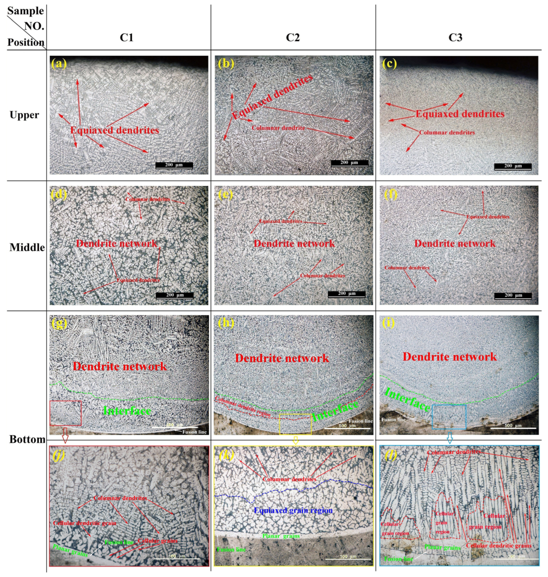
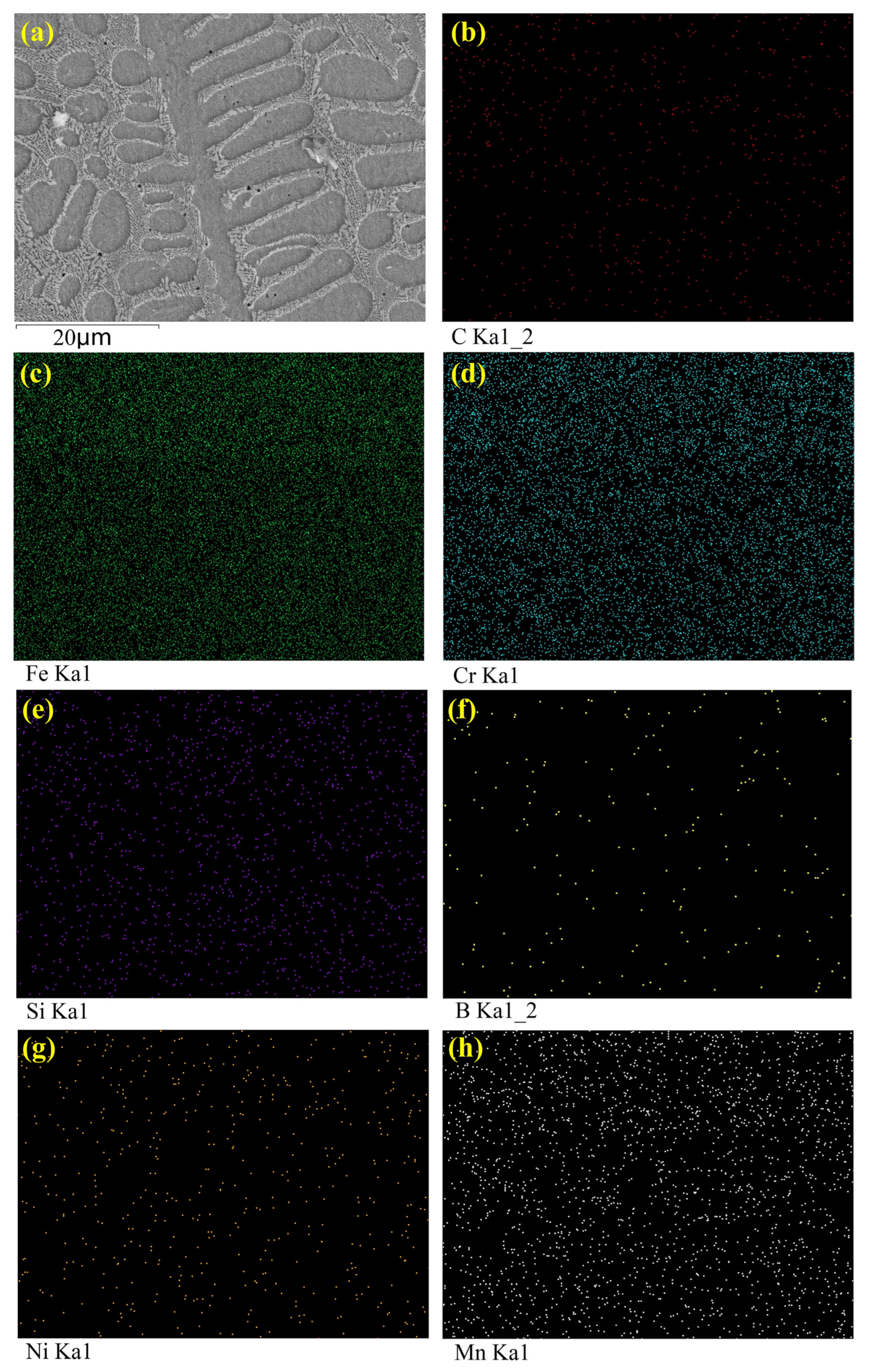
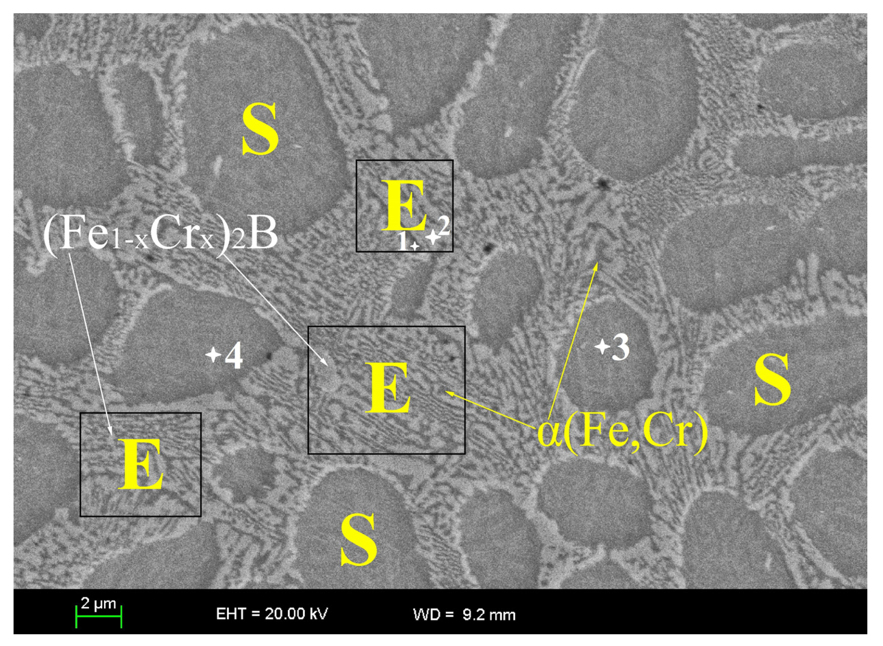
3.1. Microstructure
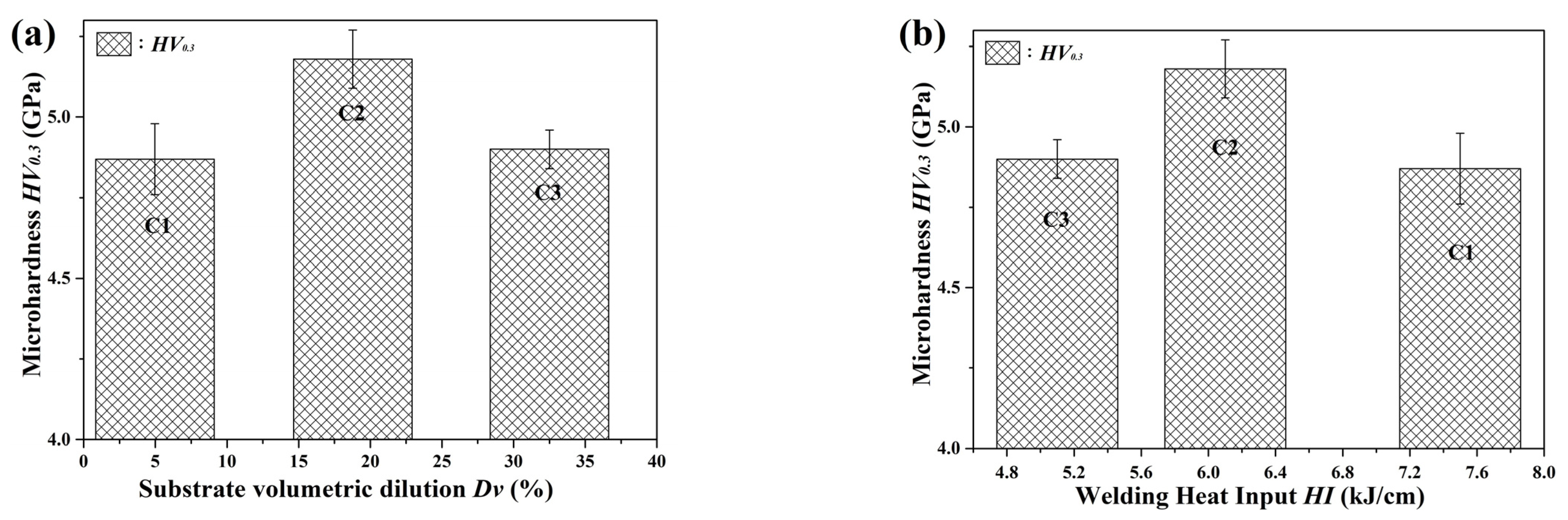
3.2. Hardness
3.3. Magnetic Properties
4. Conclusions
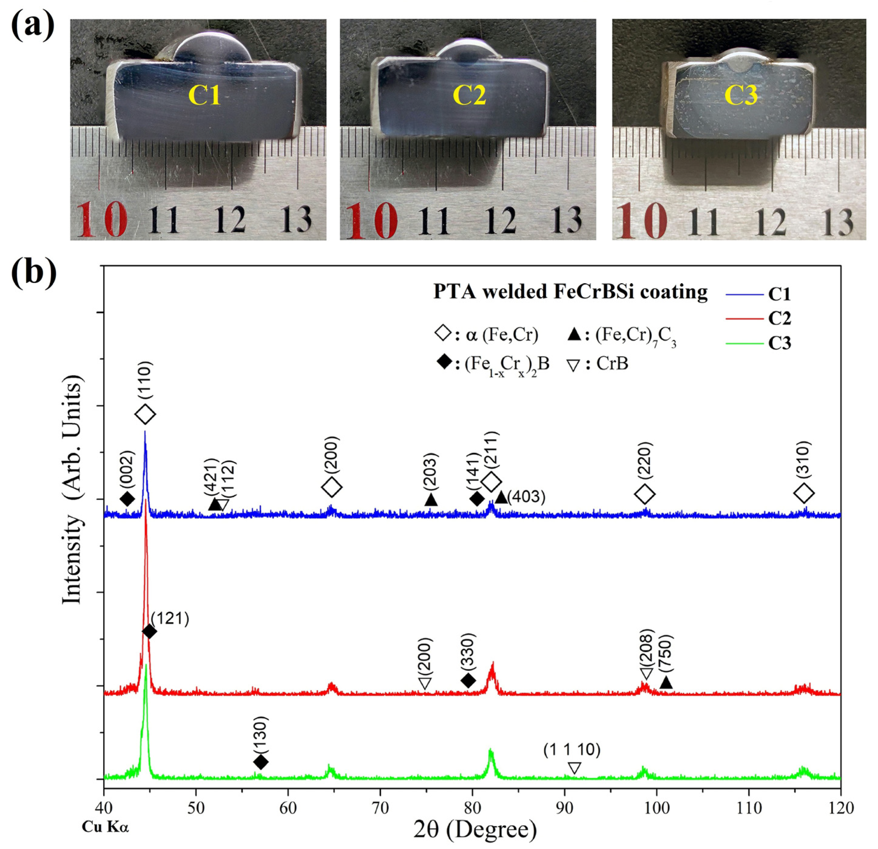
- The high-crystallinity FeCrBSi monolayer coatings were fabricated by PTA welding using Fe313 self-fluxing powders with constituents similar to AISI 430 FSS. The welded coating has hypoeutectic structures composed of columnar or equiaxed dendrites of sorbitic pearlites and interdendritic network-like α(Fe,Cr) + (Fe1−xCrx)2B eutectics, with hardness (HV > 4.5 GPa) much higher than that of AISI 430 FSS (HRB < 88 or HV < 1.8 GPa) [23] and high Ms (>1.3 T), which are not lower (or even higher) than those of the ferritic steels with the same or similar nominal compositions (1.1–1.6 T) [4,49]. This may broaden the application for AISI 430 FSS in some special fields requiring not only fair corrosion and wear resistance but also superior soft magnetic properties.
- All the welded coatings (C1, C2 and C3) have superior soft magnetic performance than the original powders, i.e., the coatings have lower Hc and higher Ms than those of the Fe313 powders. The decrease in Hc is attributed to the formation of larger grains, and the grains in the PTA-welded coatings are preferably oriented in the easiest direction of magnetization, resulting in the increase in Ms.
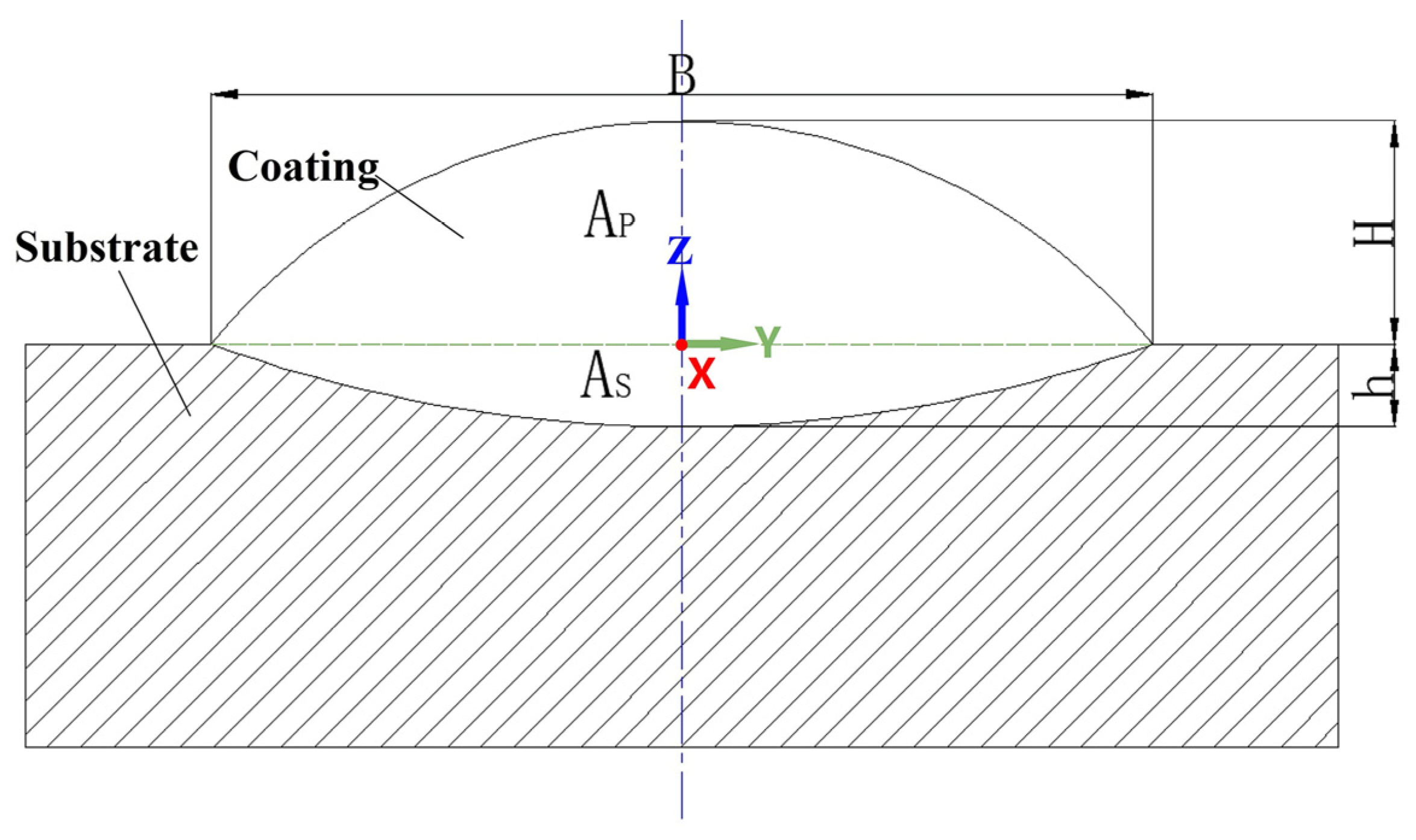
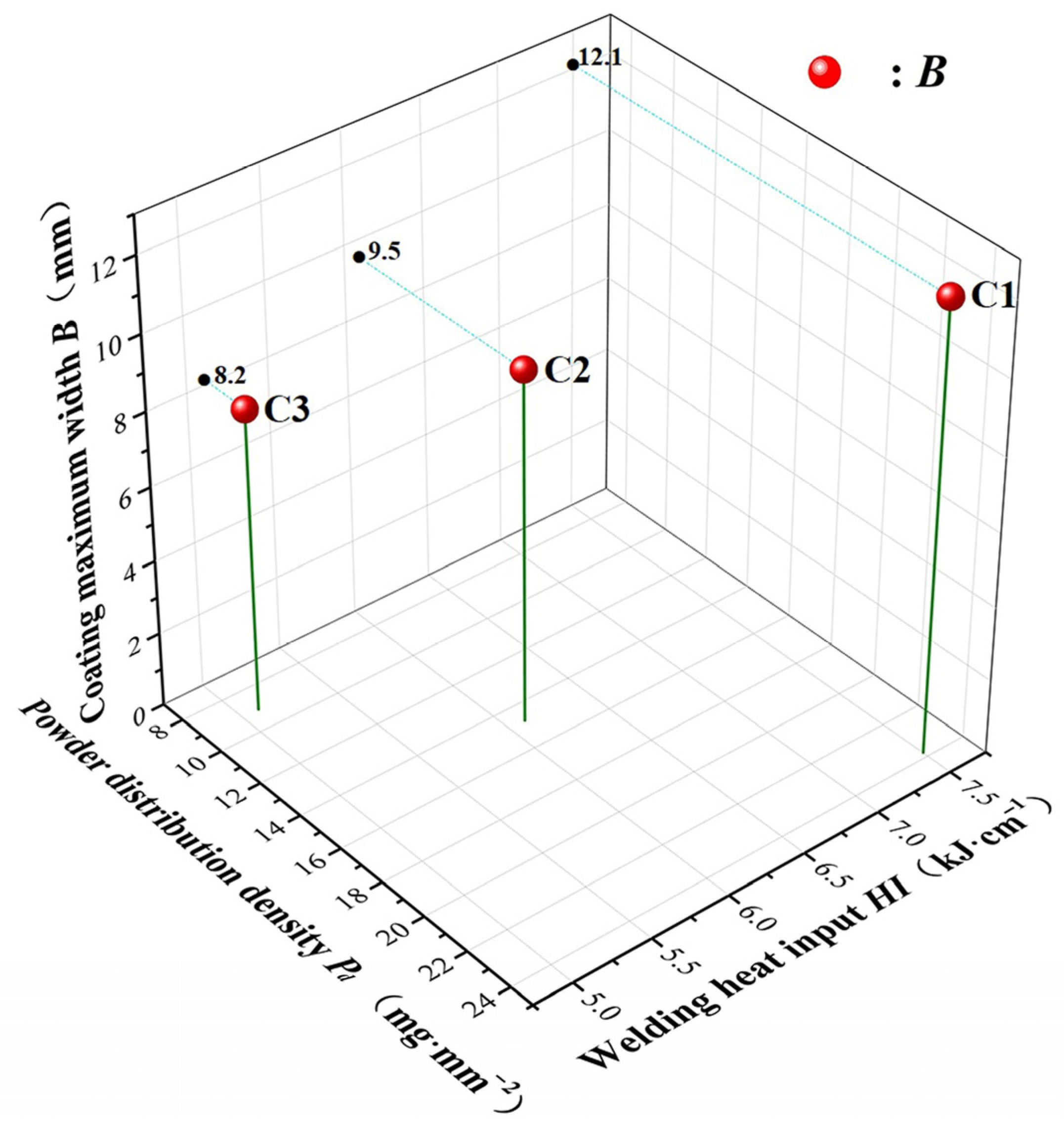
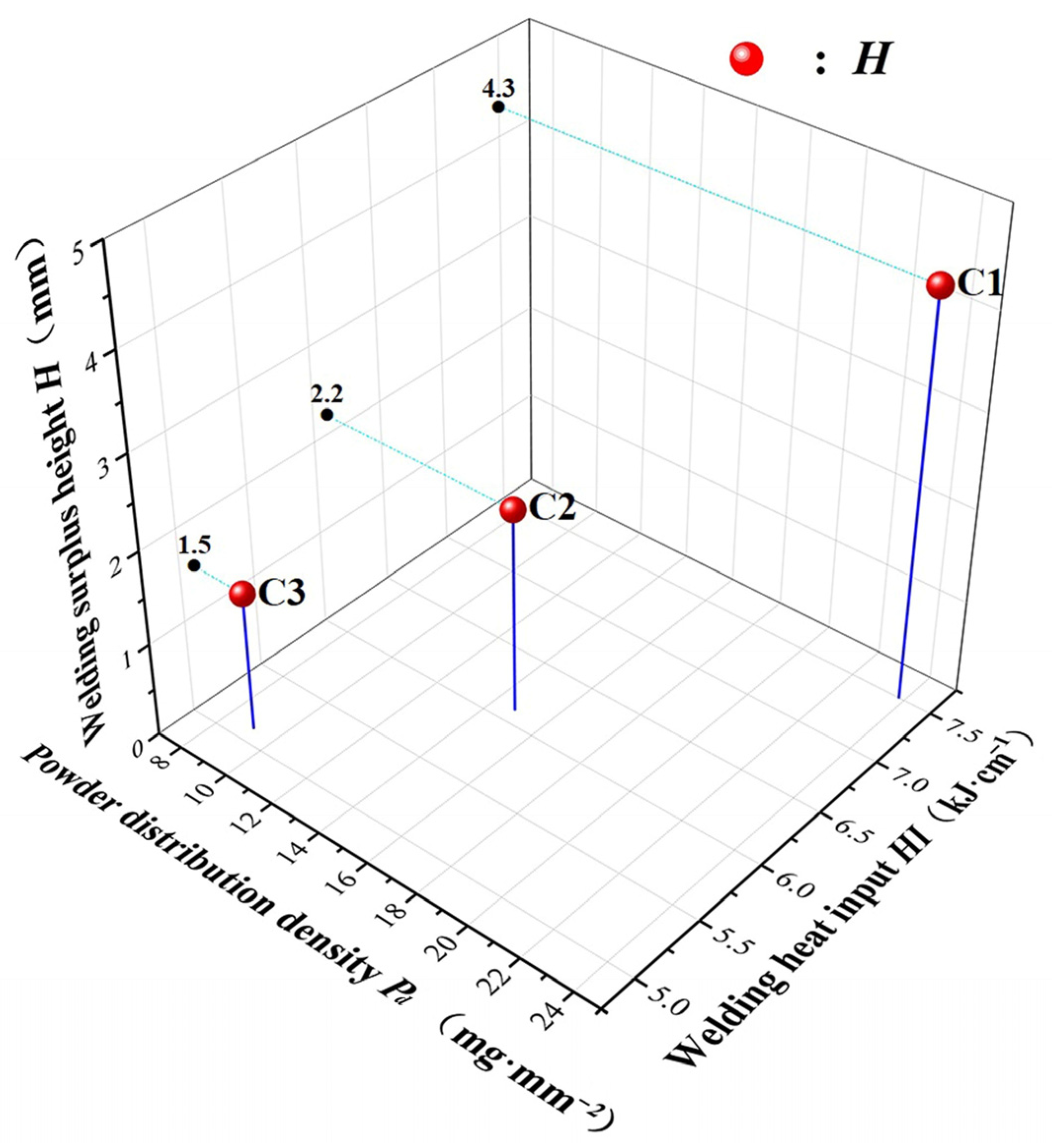
- Under the experimental conditions in this paper, the coating maximum width and the welding surplus height increase with the rise in welding HI and Pd, respectively. The coating’s Hc decreases whereas its Ms increases sharply with the growth in Dv, and the former increases but the latter decreases with the increasing welding HI. The coating C3 presents the best soft magnetic properties with Ms of 1.61 T and Hc of 58.6 Oe. The coating’s highest Ms is due to its highest Dv, lowest Vf of non-magnetic or low-Ms (compared with α-Fe) inclusions and lowest Cr content. The coating’s highest Dv and lowest Vf also are responsible for its lowest Hc.
- The high Hc of 58.6~76.4 Oe for the coatings, which resulted from the residual stress and deformation caused by the relatively rapid solidification of the PTA welding process, may be decreased by the further optimization of welding parameters or post-weld vacuum annealing, and these issues will be investigated in our follow-up research.
Author Contributions
Funding
Institutional Review Board Statement
Informed Consent Statement
Data Availability Statement
Acknowledgments
Conflicts of Interest
References
- Mallaiah, G.; Reddy, P.R.; Kumar, A. Influence of Titanium Addition on Mechanical Properties, Residual Stresses and Corrosion Behaviour of AISI 430 Grade Ferritic Stainless Steel GTA Welds. Procedia Mater. Sci. 2014, 6, 1740–1751. [Google Scholar] [CrossRef] [Green Version]
- Mostaan, H.; Rafiei, M. Prediction and Optimization of Magnetic Properties of Laser Welded AISI 430 Stainless Steels. Arch. Metall. Mater. 2018, 63, 1673–1682. [Google Scholar] [CrossRef]
- Ramkumar, K.D.; Chandrasekhar, A.; Singh, A.K.; Ahuja, S.; Agarwal, A.; Arivazhagan, N.; Rabel, A.M. Comparative Studies on the Weldability, Microstructure and Tensile Properties of Autogeneous TIG Welded AISI 430 Ferritic Stainless Steel with and without Flux. J. Manuf. Process. 2015, 20, 54–69. [Google Scholar] [CrossRef]
- Oxley, P.; Goodell, J.; Molt, R. Magnetic Properties of Stainless Steels at Room and Cryogenic Temperatures. J. Magn. Magn. Mater. 2009, 321, 2107–2114. [Google Scholar] [CrossRef]
- Battistini, L.; Benasciutti, R.; Tassi, A. Effects of Heat Treatment on Crystallographic and Magnetic Properties of Magnetic Steels. J. Magn. Magn. Mater. 1994, 133, 603–606. [Google Scholar] [CrossRef]
- Köçkar, H.; Kaplan, N.; Karpuz, A.; Kuru, H.; Kaya, B. Characterizations of Binary FeCr (AISI 430) Thin Films Deposited from a Single Magnetron Sputtering Under Easy Controllable Deposition Parameters. J. Supercond. Nov. Magn. 2019, 32, 2457–2465. [Google Scholar] [CrossRef]
- Mostaan, H.; Safari, M.; Bakhtiari, A. Micro Friction Stir Lap Welding of AISI 430 Ferritic Stainless Steel: A Study on the Mechanical Properties, Microstructure, Texture and Magnetic Properties. Metall. Res. Technol. 2018, 115, 1–10. [Google Scholar] [CrossRef]
- Mallaiah, G.; Kumar, A.; Ravinder Reddy, P.; Madhusudhan Reddy, G. Influence of Grain Refining Elements on Mechanical Properties of AISI 430 Ferritic Stainless Steel Weldments—Taguchi Approach. Mater. Des. 2012, 36, 443–450. [Google Scholar] [CrossRef]
- Ma, F.; Wang, Z.; Liu, Y.; Sha, Z.; Zhang, S. Machining Performance for Ultrasonic-Assisted Magnetic Abrasive Finishing of a Titanium Alloy: A Comparison with Magnetic Abrasive Finishing. Machines 2022, 10, 902. [Google Scholar] [CrossRef]
- Zhao, J.; Yan, W.; Han, F.; Ma, X.; Xing, L.; Du, G. Supporting Performance of Magnetic-Liquid Double Suspension Bearing under Wear of Magnetic Poles. Desalin. Water Treat. 2022, 253, 270–284. [Google Scholar] [CrossRef]
- Szczęch, M. Research into the Lubrication of a Rotary Lip Seal Using Ferrofluid. Proc. Inst. Mech. Eng. Part J J. Eng. Tribol. 2022, 236, 1186–1197. [Google Scholar] [CrossRef]
- Wang, F.; Inoue, A.; Han, Y.; Zhu, S.L.; Kong, F.L.; Zanaeva, E.; Liu, G.D.; Shalaan, E.; Al-Marzouki, F.; Obaid, A. Soft Magnetic Fe-Co-Based Amorphous Alloys with Extremely High Saturation Magnetization Exceeding 1.9 T and Low Coercivity of 2 A/M. J. Alloys Compd. 2017, 723, 376–384. [Google Scholar] [CrossRef]
- Han, L.; Maccari, F.; Souza Filho, I.R.; Peter, N.J.; Wei, Y.; Gault, B.; Gutfleisch, O.; Li, Z.; Raabe, D. A Mechanically Strong and Ductile Soft Magnet with Extremely Low Coercivity. Nature 2022, 608, 310–316. [Google Scholar] [CrossRef] [PubMed]
- Feldshtein, E.; Kardapolava, M.; Dyachenko, O. On the Effectiveness of Multi-Component Laser Modifying of Fe-Based Self-Fluxing Coating with Hard Particulates. Surf. Coat. Technol. 2016, 307, 254–261. [Google Scholar] [CrossRef]
- Yi, P.; Liu, Y.; Fan, C.; Zhan, X.; Xu, P.; Liu, T. Impact Analysis of the Thermal Mechanical Coupling Characteristics of Graphite Morphologies during Laser Cladding of Gray Cast Iron. Opt. Laser Technol. 2017, 90, 52–64. [Google Scholar] [CrossRef]
- Sun, Y.Z.; Liu, S.; Wang, S.Y.; Li, J.B.; Yang, C.N.; Hai, B.R.; Zhang, X.R.; Liu, C.S. Study on Macroscopic Morphology, Microstructure and Hardness of F313 Iron-Based Coatings Prepared by Laser Cladding Using Different Powder Feed Rate. Adv. Mater. Res. 2015, 1095, 631–635. [Google Scholar] [CrossRef]
- Yu, T.; Yang, L.; Zhao, Y.; Sun, J.; Li, B. Experimental Research and Multi-Response Multi-Parameter Optimization of Laser Cladding Fe313. Opt. Laser Technol. 2018, 108, 321–332. [Google Scholar] [CrossRef]
- Kalpakjian, S.; Schmid, S.R. Manufacturing Engineering and Technology, 7th ed.; Pearson Education Limited: Essex, UK, 2014; ISBN 9789810694067. [Google Scholar]
- Huang, H.; Han, G.; Qian, Z.; Liu, Z. Characterizing the Magnetic Memory Signals on the Surface of Plasma Transferred Arc Cladding Coating under Fatigue Loads. J. Magn. Magn. Mater. 2017, 443, 281–286. [Google Scholar] [CrossRef]
- Wilden, J.; Bergmann, J.P.; Frank, H. Plasma Transferred Arc Welding—Modeling and Experimental Optimization. J. Therm. Spray Technol. 2006, 15, 779–784. [Google Scholar] [CrossRef]
- Fu, Y.; Pan, Z.; Li, L.; Wang, H.; Zhao, L.; Liu, C. Fe-Co-Based Crystalline Soft Magnetic Coatings with Ultra-High Saturation Magnetization above 1.9T via Co-Axial Powder Feeding Plasma-Transferred Arc Welding. J. Mater. Sci. Mater. Electron. 2023, 34, 468. [Google Scholar] [CrossRef]
- Fu, Y.; Li, L.; Guo, X.; Li, M.; Pan, Z.; Wang, H. Fe-Co-Based Coating with High Hardness and High Saturation Magnetization Deposited by Co-Axial Powder Feeding Plasma Transferred Arc Welding. Mater. Lett. 2022, 315, 131928. [Google Scholar] [CrossRef]
- Available online: https://www.efunda.com/mateials (accessed on 2 March 2023).
- Farias, F.W.C.; da Cruz Payão Filho, J.; da Silva Júnior, D.A.; de Moura, R.N.; Rios, M.C.G. Microstructural Characterization of Ni-Based Superalloy 625 Clad Welded on a 9% Ni Steel Pipe by Plasma Powder Transferred Arc. Surf. Coat. Technol. 2019, 374, 1024–1037. [Google Scholar] [CrossRef]
- Bharath, R.R.; Ramanathan, R.; Sundararajan, B.; Srinivasan, P.B. Optimization of Process Parameters for Deposition of Stellite on X45CrSi93 Steel by Plasma Transferred Arc Technique. Mater. Des. 2008, 29, 1725–1731. [Google Scholar] [CrossRef]
- Wang, D.; Ma, L.; Li, L.; Xu, X.L.; Guo, Y.B.; Zhao, S.Q. Characterization of Polycrystalline Fe2B Compound with High Saturation Magnetization. J. Supercond. Nov. Magn. 2018, 31, 431–435. [Google Scholar] [CrossRef]
- Tianshun, D.; Xiaodong, Z.; Yalong, L.; Guolu, L.; Xiukai, Z.; Haidou, W. Microstructure and Wear Resistance of FeCrBSi Plasma-Sprayed Coating Remelted by Gas Tungsten Arc Welding Process. J. Mater. Eng. Perform. 2018, 27, 4069–4076. [Google Scholar] [CrossRef]
- Bermingham, M.J.; StJohn, D.H.; Krynen, J.; Tedman-Jones, S.; Dargusch, M.S. Promoting the Columnar to Equiaxed Transition and Grain Refinement of Titanium Alloys during Additive Manufacturing. Acta Mater. 2019, 168, 261–274. [Google Scholar] [CrossRef]
- Wang, W.L.; Liu, W.Q.; Yang, X.; Xu, R.R.; Dai, Q.Y. Multi-Scale Simulation of Columnar-to-Equiaxed Transition during Laser Selective Melting of Rare Earth Magnesium Alloy. J. Mater. Sci. Technol. 2022, 119, 11–24. [Google Scholar] [CrossRef]
- Kou, S. Welding Metallurgy, 2nd ed.; John Wiley & Sons, Inc.: Hoboken, NJ, USA, 2003; ISBN 0471434914. [Google Scholar]
- Gutierrez, A.; Lippold, J.C.; Lin, W. Nondendritic Equiaxed Zone Formation in Aluminum-Lithium Welds. Mater. Sci. Forum 1996, 217–222, 1691–1696. [Google Scholar] [CrossRef]
- Shakil, M.; Ahmad, M.; Tariq, N.H.; Hasan, B.A.; Akhter, J.I.; Ahmed, E.; Mehmood, M.; Choudhry, M.A.; Iqbal, M. Microstructure and Hardness Studies of Electron Beam Welded Inconel 625 and Stainless Steel 304L. Vacuum 2014, 110, 121–126. [Google Scholar] [CrossRef]
- Basak, A.; Das, S. Epitaxy and Microstructure Evolution in Metal Additive Manufacturing. Annu. Rev. Mater. Res. 2016, 46, 125–149. [Google Scholar] [CrossRef]
- Gäumann, M.; Henry, S.; Cléton, F.; Wagnière, J.D.; Kurz, W. Epitaxial Laser Metal Forming: Analysis of Microstructure Formation. Mater. Sci. Eng. A 1999, 271, 232–241. [Google Scholar] [CrossRef]
- Wang, T.; Zhu, Y.Y.; Zhang, S.Q.; Tang, H.B.; Wang, H.M. Grain Morphology Evolution Behavior of Titanium Alloy Components during Laser Melting Deposition Additive Manufacturing. J. Alloys Compd. 2015, 632, 505–513. [Google Scholar] [CrossRef]
- Wang, Q.; Chen, F.Q.; Zhang, L.; Li, J.D.; Zhang, J.W. Microstructure Evolution and High Temperature Corrosion Behavior of FeCrBSi Coatings Prepared by Laser Cladding. Ceram. Int. 2020, 46, 17233–17242. [Google Scholar] [CrossRef]
- Lu, J.Z.; Cao, J.; Lu, H.F.; Zhang, L.Y.; Luo, K.Y. Wear Properties and Microstructural Analyses of Fe-Based Coatings with Various WC Contents on H13 Die Steel by Laser Cladding. Surf. Coat. Technol. 2019, 369, 228–237. [Google Scholar] [CrossRef]
- Luo, K.Y.; Xu, X.; Zhao, Z.; Zhao, S.S.; Cheng, Z.G.; Lu, J.Z. Microstructural Evolution and Characteristics of Bonding Zone in Multilayer Laser Cladding of Fe-Based Coating. J. Mater. Process. Technol. 2019, 263, 50–58. [Google Scholar] [CrossRef]
- Gao, W.; Zhang, Z.; Zhao, S.; Wang, Y.; Chen, H.; Lin, X. Effect of a Small Addition of Ti on the Fe-Based Coating by Laser Cladding. Surf. Coat. Technol. 2016, 291, 423–429. [Google Scholar] [CrossRef]
- Kumar, A.; Roy, S. Effect of Three-Dimensional Melt Pool Convection on Process Characteristics during Laser Cladding. Comput. Mater. Sci. 2009, 46, 495–506. [Google Scholar] [CrossRef]
- Okamoto, H. Phase Diagrams for Binary Alloys, 2nd ed.; ASM International: Materials Park, OH, USA, 2010; ISBN 9781615030460. [Google Scholar]
- Nakaidze, S.; Garibashvili, V.; Antadze, M.; Tsagareishvili, O. Neutron-Absorption Deformable Boron-Rich Ferrous Alloys. J. Solid State Chem. 2004, 177, 592–595. [Google Scholar] [CrossRef]
- Ge, C.L.; Ye, R.C. Research on Self-Propagating Eutectic Boriding. J. Mater. Process. Technol. 2002, 124, 14–18. [Google Scholar] [CrossRef]
- Eroglu, M. Boride Coatings on Steel Using Shielded Metal Arc Welding Electrode: Microstructure and Hardness. Surf. Coat. Technol. 2009, 203, 2229–2235. [Google Scholar] [CrossRef]
- Yu, R.H.; Basu, S.; Ren, L.; Zhang, Y.; Parvizi-Majidi, A.; Unruh, K.M.; Xiao, J.Q. High Temperature Soft Magnetic Materials: FeCo Alloys and Composites. IEEE Trans. Magn. 2000, 36, 3388–3393. [Google Scholar] [CrossRef]
- Podurets, K.M.; Shilstein, S.S. Measurement of the Domain Wall Thickness in Silicon Iron Using the Adiabatic Spin-Flip Effect on Neutron Refraction. Phys. B Condens. Matter 2001, 297, 263–267. [Google Scholar] [CrossRef]
- Li, L.; Li, W.; Zhang, B.; Wang, B.; Zang, X. In-Situ Observation of Growth Characteristics of M7C3 Carbides in Hypoeutectic Fe-Cr-C Alloys. Mater. Charact. 2022, 191, 112143. [Google Scholar] [CrossRef]
- Yun, X.; Zhou, Y.F.; Zhao, B.; Xing, X.L.; Yang, J.; Yang, Y.L.; Yang, Q.X. Influence of Nano-Y2O3 on Wear Resistance of Hypereutectic Fe-Cr-C Hardfacing Coating. Tribol. Lett. 2015, 58, 23. [Google Scholar] [CrossRef]
- Deantonio, D.A. Soft magnetic ferritic stainless steels. Adv. Mater. Processes. 2003, 161, 29–32. [Google Scholar]
- Aldred, A.T. Ferromagnetism in Iron-Chromium Alloys. I. Bulk Magnetization Measurements. Phys. Rev. B 1976, 14, 219–227. [Google Scholar] [CrossRef]


| Materials | C | Si | B | Cr | Ni | Cu | Mn | S | P | Fe |
|---|---|---|---|---|---|---|---|---|---|---|
| AISI 1010 | 0.07–0.14 | 0.17–0.37 | - | ≤0.15 | ≤0.25 | ≤0.25 | 0.35–0.65 | ≤0.04 | ≤0.35 | Bal. |
| Fe313 | 0.1–0.2 | 1.0–1.5 | 1.0–2.0 | 14.0–18.0 | 0.2–0.5 | - | 0.2–0.5 | - | - | Bal. |
| AISI 430 [23] | 0.12 | 1.00 | - | 16.0–18.0 | - | - | 1.00 | 0.03 | 0.04 | Bal. |
| Parameter | Value |
|---|---|
| Plasma gas (Ar) flow rate/(L·min−1) | 7.5 |
| Carrier gas (Ar) flow rate/(L·min−1) | 7.0 |
| Shielding gas (Ar) flow rate/(L·min−1) | 8.0 |
| Stand-off distance/mm | 13 |
| Preheat temperature/°C | 25 |
| Internal diameter of coaxial nozzle D/mm | 6 |
| Sample No. | C-I | C-II | C-III | C1 | C2 | C3 |
|---|---|---|---|---|---|---|
| Welding current I/A | 75 | 85 | 95 | 100 | 100 | 100 |
| Transferred arc voltage U/V (average) | 22.5 | 22.5 | 22.5 | 25.1 | 26.3 | 26.8 |
| Powder feed rate F/(g·min−1) | 16 | 16 | 16 | 20 | 16 | 12 |
| Welding speed S/(m·min−1) | 0.16 | 0.16 | 0.16 | 0.14 | 0.18 | 0.22 |
| Powder distribution density Pd/(mg·mm−2) | 16.7 | 16.7 | 16.7 | 23.8 | 14.8 | 9.1 |
| Welding heat input HI/(kJ·cm−1) [η = 0.7] (average) | 4.4 | 5.0 | 5.6 | 7.5 | 6.1 | 5.1 |
| Welding surplus height H/mm | 1.7 | 1.5 | 1.2 | 4.3 | 2.2 | 1.5 |
| Maximum width B/mm | 5.3 | 4.9 | 4.8 | 12.1 | 9.5 | 8.2 |
| Volumetric dilution ratio Dv/% (average) | 0.6 | 3.6 | 7.6 | 4.97 | 18.78 | 32.50 |
| Microhardness HV0.3/GPa (average) | 5.67 ± 0.17 | 5.83 ± 0.19 | 5.53 ± 0.19 | 4.87 ± 0.11 | 5.18 ± 0.09 | 4.90 ± 0.06 |
| Saturation magnetization Ms/T | 0.23 | 0.82 | 1.44 | 1.42 | 1.47 | 1.61 |
| Coercivity Hc/Oe | 113.4 | 70.0 | 109.8 | 76.4 | 74.2 | 58.6 |
| Elements | Weight Percent (wt.%) | |||
|---|---|---|---|---|
| Point 1 | Point 2 | Point 3 | Point 4 | |
| Fe | 66.46 | 61.54 | 77.59 | 65.77 |
| Cr | 14.18 | 16.26 | 12.63 | 11.05 |
| B | 11.76 | 13.13 | - | - |
| Si | 0.65 | 0.51 | 1.32 | 1.34 |
| C | 6.95 | 8.07 | 8.07 | 21.47 |
| Mn | - | 0.49 | 0.39 | 0.36 |
| Ni | - | - | - | - |
Disclaimer/Publisher’s Note: The statements, opinions and data contained in all publications are solely those of the individual author(s) and contributor(s) and not of MDPI and/or the editor(s). MDPI and/or the editor(s) disclaim responsibility for any injury to people or property resulting from any ideas, methods, instructions or products referred to in the content. |
© 2023 by the authors. Licensee MDPI, Basel, Switzerland. This article is an open access article distributed under the terms and conditions of the Creative Commons Attribution (CC BY) license (https://creativecommons.org/licenses/by/4.0/).
Share and Cite
Fu, Y.; Wang, H.; Huang, W.; Pan, Z.; Liu, C.; Zhao, L.; Li, C.; Zhu, L.; Huang, N. PTA-Welded Coatings with Saturation Magnetization above 1.3 T Using FeCrBSi Powders with Chemical Composition Similar to AISI 430 Ferrite Stainless Steel. Magnetochemistry 2023, 9, 93. https://doi.org/10.3390/magnetochemistry9040093
Fu Y, Wang H, Huang W, Pan Z, Liu C, Zhao L, Li C, Zhu L, Huang N. PTA-Welded Coatings with Saturation Magnetization above 1.3 T Using FeCrBSi Powders with Chemical Composition Similar to AISI 430 Ferrite Stainless Steel. Magnetochemistry. 2023; 9(4):93. https://doi.org/10.3390/magnetochemistry9040093
Chicago/Turabian StyleFu, Yingqing, Haiming Wang, Wenhao Huang, Zhoujian Pan, Changhao Liu, Lei Zhao, Chao Li, Liangyu Zhu, and Naibao Huang. 2023. "PTA-Welded Coatings with Saturation Magnetization above 1.3 T Using FeCrBSi Powders with Chemical Composition Similar to AISI 430 Ferrite Stainless Steel" Magnetochemistry 9, no. 4: 93. https://doi.org/10.3390/magnetochemistry9040093