1. Introduction
Magnetorheological fluid (MRF) is a type of intelligent material. It behaves like a fluid generally, and just under the action of a magnetic field, its rheological properties change from liquid to semi-solid (chain-like structure) within milliseconds [
1]. With the disappearance of the magnetic field, it returns to its original state [
2]. Due to the unique rheological properties of the MRF, it is widely used in mechanical devices such as brakes, clutches, and dampers [
3]. The magnetorheological damper (MRD) is a damping device that uses the MRF’s viscosity change under a magnetic field’s action to control and adjust the damping force change [
4]. Traditional passive dampers are usually difficult to measure and have high energy consumption, time lag, and overflow. In contrast, MRDs have excellent dynamic characteristics such as fast response, stable environmental features, large capacity, low power consumption, simple structure, and continuously adjustable damping force. MRDs also can realize semi-active vibration control and are easy to combine with computers for intelligent control [
5].
In 1994, Lord Company applied MRD to the commercial automobile market and human prostheses. Since then, MRD devices have begun to develop rapidly. Since the 1990s, MRD has gradually been developed and applied in vibration control. In 1999, MRD was used to study the vibration control of a quarter-car model suspension system with good suppression results [
6]. In 2002, the American company Delphi invented a magnetorheological shock absorber, and the Cadillac Seville STS first used it in the same year. In 2004, Ahmadian et al. designed a typical double-ended MRD and used many experiments to study its rheological control under impact loading [
7]. In 2005, Ahn et al. [
8]. developed a MRD applied to a small variable damping bracket for automotive precision equipment. In 2007, Batterbee et al. [
9]. used MRFs to achieve semi-active damping control of aircraft landing gear and proposed an optimal design method for landing MRD. In 2015, Guo et al. [
10] designed a bypass MRD with radial runners and applied it to a transverse suspension system for railway vehicles. In 2017, Gao et al. [
11] developed a smart prosthetic knee joint using a direct current motor, MRD, and spring, broadening the range of applications for MRDs. In 2019, Sun et al. [
12] designed a variable stiffness and MRD vehicle suspension system to provide an effective method for further improving vehicle performance and driver comfort. As technology evolves, various more advanced MRD technologies have been developed and successfully applied in different areas of vibration control, such as vehicle suspension systems [
13,
14], passenger tracks [
15,
16], aircraft landing gear [
17,
18], vessels [
19], earthquake-resistant building protection [
20,
21], advanced prosthetic system [
22], military field [
23,
24], etc.
MRD has become a research hotspot in the intelligent materials and vibration control field. The number of research papers published on it is increasing yearly. Many scholars have reviewed relevant literature to understand the latest research progress and future development trends quickly. Yuan et al. [
25] reviewed the structural development of the three technical directions of the position and the number of turns of the coil, the improvement of the magnetic circuit, and the innovative flow pattern, and also supplemented the structure and technical characteristics of the current MRD, and analyzed the future demand to predict the development trend and new applications. Rahman et al. [
26] summarized the optimal design, manufacture, and intelligent application of various MRDs, suggesting that energy efficiency is the ultimate development requirement and that self-powered and self-induced MRDs offer good prospects for development; Rossi et al. [
27] provided an overview of MRD modeling and characterization, briefly reviewing the main mathematical models used and focusing on issues arising from experimental characterization. Hu Guoliang et al. [
28] mainly analyzed the structure of functionally integrated MRDs, such as vibration energy harvesting and self-sensing self-powered types, and the current development status of their application in vehicle suspensions. This work can provide a theoretical reference for the structural design and engineering application of functionally integrated MRDs. Hua et al. [
3] summarized the most advanced MRF mechanical equipment from 2018 to 2020, mainly introducing the outstanding innovation and progress of new medical equipment of MRF, proposed improvement plans, and prospected the development trend of this new type of application.
Consolidation and analysis of the existing literature revealed that the current studies summarized less about the application of MRD in the latest structural design and different fields. This paper aims to summarize the latest developments in the structures of MRD and provide an overview of its latest applications in the defense industry, vehicle engineering, civil engineering, traffic engineering, aerospace, and other areas. At the end of this paper, it concludes with an outlook on potential applications. The research in this paper has important implications for the development of MRD technology and applied research.
2. Basic Introduction of MRD
MRD is a semi-active control damping device using MRF as the working medium. Its damping effect is significantly better than the traditional oil pressure damper. The mounting position of the core in MRD is generally divided into internal and external (bypass) types [
29].
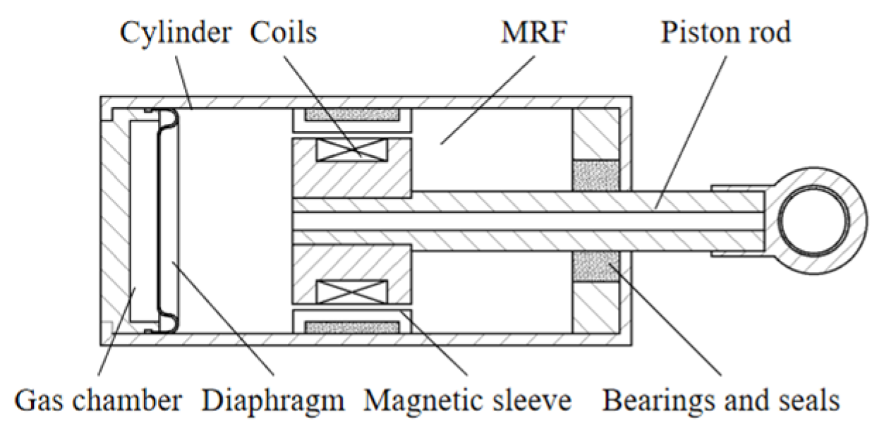
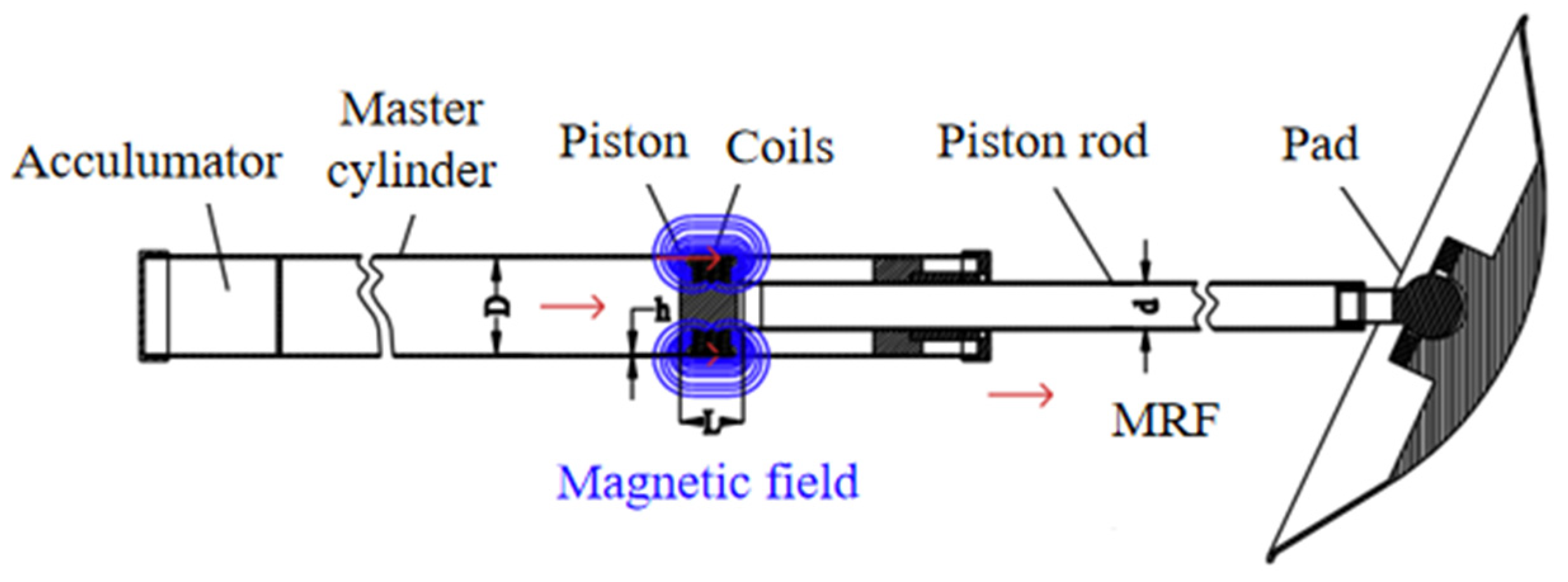
The internal MRD is a typical design structure, and its magnetic core is usually located on the piston in the cylinder, as shown in
Figure 1.
In a typical internal MRD, the MRF flows in the gap between the inner and outer piston, piston, and cylinder. The coil generates a magnetic field when the current is applied, and the MRF in the gap becomes solid-like, thus changing the force required to move the piston, creating a controlled damping force. The advantages are simple configuration, compact design, small space requirements, and step-less damping force adjustment. The damping channel of internal MRD is generally set between the piston and the inner wall of the working chamber in the form of an annular column. The interior space size limits the damping channel. Secondly, the coils generate the magnetic field required to operate the MRF. The coils are usually placed on the piston, so the actual damping channel length during operation is smaller than the ideal damping channel, making its magnetic field utilization low. Furthermore, the magnetic cores are located with the MRF in the working chamber, leading to leakage of the MRF due to improper sealing and affecting the dampers’ service life.
The magnetic core of an external (bypass) MRD is in the bypass of the working chamber, separate from the internal piston. Due to the instability of MRF, it is prone to settling on the surface of the cylinder, affecting the damper’s working performance. In comparison, the bypass type can effectively reduce the deposition of the MRF.
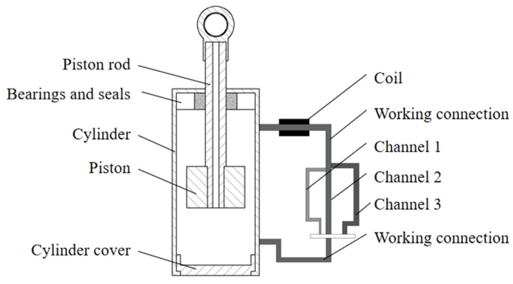
Figure 2 shows a typical multi-stage bypass MRD designed by Kou et al. [
30].
The magnetic core is outside the cylinder, and the coil detaches from the piston. The MRF can pass through the three damping channels of oil circuits 1, 2, and 3, and the diameter of the channels increases in turn. Selecting the appropriate damping channel can control the damping force required to operate the damper. The piston of the bypass MRD divides the cylinder into two chambers. The MRF flows through the two chambers through the bypass, with the damping channel in the working gap between the bypass cylinder and the magnetic pole. A suitable bypass magnetic core can increase the length of the damping channel without being limited by the piston stroke, thus achieving a more excellent dynamic range of damping forces. External bypass magnetic cores can be installed into different cylinder configurations for incredible flexibility. The electromagnetic circuit is located outside the main cylinder, which is easy to repair [
31]. However, bypassing MRDs requires a large volume and a complex structure.
In addition to being classified by the magnetic core’s installation position, MRD can also be classified by the MRF working mode. MRFs have four basic working modes: (1) flow (valve) mode—fluid flow due to pressure gradient between two fixed plates, usually used for servo valves, dampers, and buffers; (2) shear mode—the fluid is between two relatively moving plates, often used in clutches, brakes, and dampers; (3) squeeze mode—the fluid flows between two plates moving perpendicular to their plane, used only for slight amplitude vibration and shock dampers. Conventional MRDs generally use one of three modes, with the flow (valve) mode being the most used. (4) Pinch mode—arranging the poles axially along the flow path and separating the poles by a non-magnetic spacer generates a highly non-uniform magnetic field. There is less research about this mode than the first three operating modes. The advantages and disadvantages of the four working modes as shown in
Table 1.
Based on the MRD magnetic core structure and the MRF working mode, the improvement of a single component does not meet the design requirements well in the face of multiple engineering application scenarios. As a result, several studies have gradually developed hybrid MRDs to suit more complex applications and obtain better operating performance. According to the current research results, hybrid MRDs can be classified into hybrid working mode, power, and particular part types. The following will summarize the latest research progress developments in new MRDs in three main directions: internal, bypass, and hybrid, providing an advanced basis for the research and design of MRDs.
3. New Structures of Internal MRD
3.1. Number and Arrangement of Coils
The excitation coil is a critical component in providing an external magnetic field to the MRF in the MRD to excite the magnetorheological effect. In previous studies, designing the number and arrangement of coils was a common idea to optimize the operating performance of the dampers. A conventional MRD usually arranges the coils in two main ways:
(1) The coil embeds in the piston, and the piston bore connects the wire to an external power supply, thus generating a magnetic field. The advantage of this arrangement is the simplicity of the design and the better magnetic utilization. However, there are the following problems: By the coil being in direct contact with the MRF, the fluid will leak through it; and the seals will complicate the manufacturing process. In addition, the internal temperature rise may make the viscosity of MRF decrease significantly, leading to the attenuation of the output performance of the MRD.
(2) The coil on the working cylinder body is separated from the piston. This arrangement can improve the sealing performance, but the magnetic field utilization is lower.
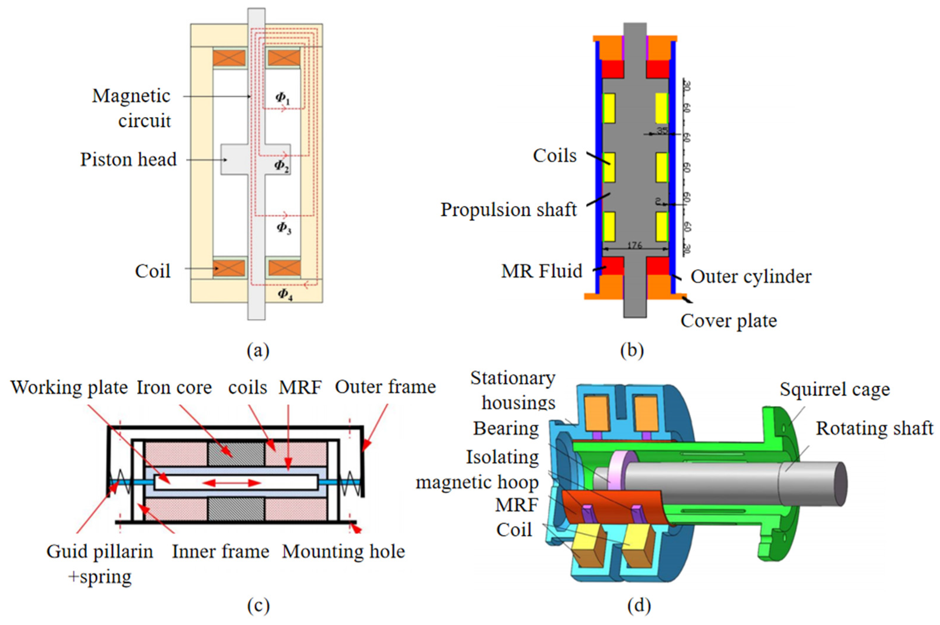
In response to the above problems, many scholars have recently improved the number of coils and coil arrangements based on previous research, thus optimizing the damper structure and improving the damper performance. Lee et al. [
32] proposed a new magnetic circuit separate from the MRD piston head, as shown in
Figure 3a, where two coils are mounted at the top and bottom of the damper and surrounded by a cover plate made of ferromagnetic material. The coils separate from the piston have a higher dynamic control range, and the damping force of this structure can vary by up to 11%. However, the total stroke length limits the damping force and is suitable for small strokes with low damping. Yang et al. [
33] explored the complex magnetic field distribution inside a multi-coil MRD based on a three-coil structure with an embedded Hall sensor, as shown in
Figure 3b. They proposed a magnetic field coupling model with coupling coefficients to describe the complex magnetic field distribution and coupling effects of the three-coil MRD. It can represent the magnetic field distribution of other multi-coil MRDs, laying the foundation for the optimal design of magnetic circuits and mathematical models of multi-coil MRDs. Chen et al. [
34] designed a two-dimensional planar plate type MRD with bipolar coils for achieving two-dimensional damping in engineering, as shown in
Figure 3c. By controlling the windings’ direction of the coils to obtain a superimposed magnetic field in the damper’s working gap, the MRF acting on the working plate is the controllable damping force of this damper. The larger the shear rate, the more pronounced the damping should be. The maximum damping ratio of the amplitude can reach 2.5956. The proposed 2-D plate-type MRD has better damping performance. Ma et al. [
35] proposed a model of a rotor-bearing system supported by an MRD as shown in
Figure 3d. It has a double coil, and the coils must be wound in opposite directions to control the rotor vibration by applying a suitable current to generate a response damping force. It provides proper damping and stiffness for the rotor system to realize the optimal control of rotor system vibration. The damper overcomes the shortcomings of the traditional squeeze film damper, such as a narrow tuning range and failure of vibration reduction due to fault or sudden unbalance.
3.2. Piston Structure Optimization
The piston of a general MRD consists of a piston head, a piston rod, and an embedded coil. When the force of the applied load transmits through the piston rod into the damper, the piston rod moves relative to the damper cylinder. When the coil energizes, it generates a magnetic field. The MRF in the gap between the piston and the cylinder enters a flow or shear mode of operation, resulting in a controlled damping force due to the magnetorheological effect. The conventional piston structure is simple, but the size of the damper limits its piston stroke, thus limiting the damping force and the range of adjustment, and the magnetic utilization of the simple piston structure is low. To optimize the design of the piston so that the damper can produce a sizeable damping force and dynamic range even with restricted dimensions and to improve the overall damper performance, researchers have recently improved or replaced the piston of the MRD.
Jiang et al. [
36] designed an MRD with an inner piston channel, as shown in
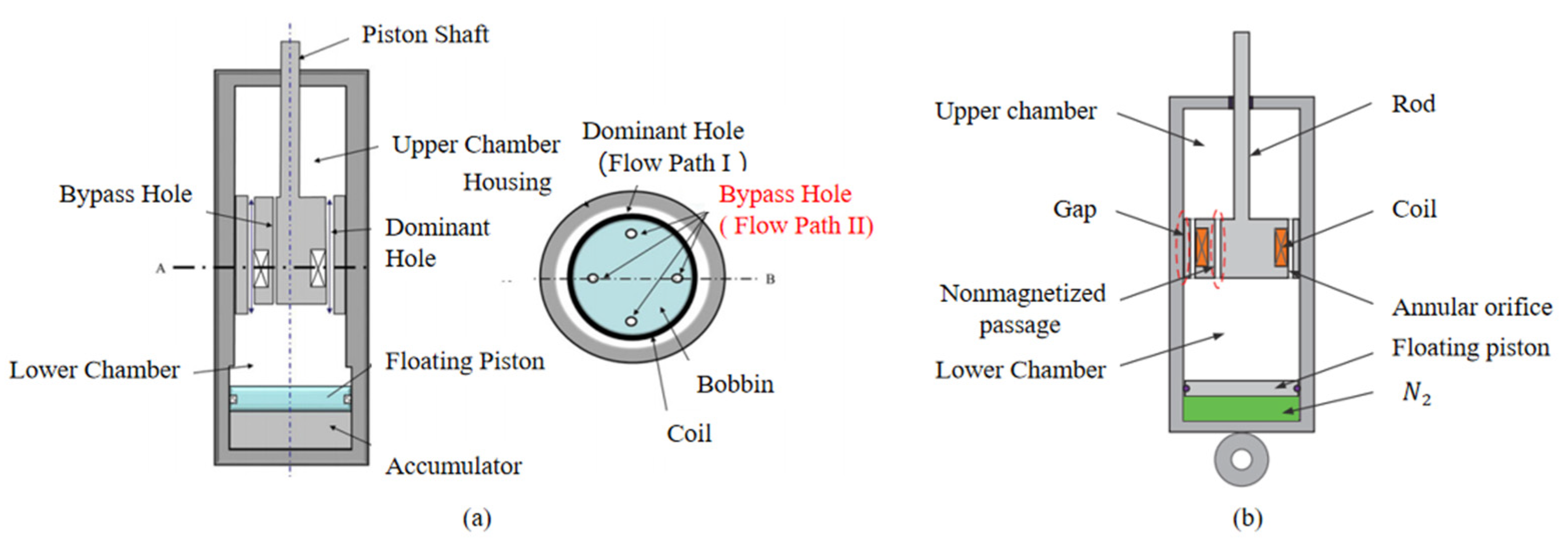
Figure 4a, that integrates the magnetic circuit in the piston assembly without passing through the cylinder. The damper is lightweight, electromagnetic compatible, and highly integrated. They optimized the structure by a non-explicit ranking genetic algorithm version II with the maximum dynamic range and a minimum number of turns of the solenoid coil as the optimization objectives. This optimization can provide a reference for the optimal design of related damping devices. Oh et al. [
37] compared two types of MRD, as
Figure 4b shows, one with two different bypass holes in the piston, and the MRD with the bypass hole had the central hole and two additional bypass holes in the runners. A simulation study concluded that the MRD with the bypass hole in the low piston speed region had less damping force, better energy dissipation performance in body resonance (1–2 Hz), and superior ride quality in passenger mode (3–10 Hz). Li et al. [
38] developed a mathematical model that can efficiently predict the damping force of MRDs with non-magnetized channels in the piston. These studies show that it works better over various piston velocities, indicates damping force, and evaluates performance. Further, Liu et al. [
39] validated the advantages of MRD with multi-grooves through experiments for the first time. Compared with MRD without multi-grooves, a MRD with multi-grooves has a more significant damping force and controllable force range and less increment of fluid viscous force while keeping the same increase in field-dependent force.
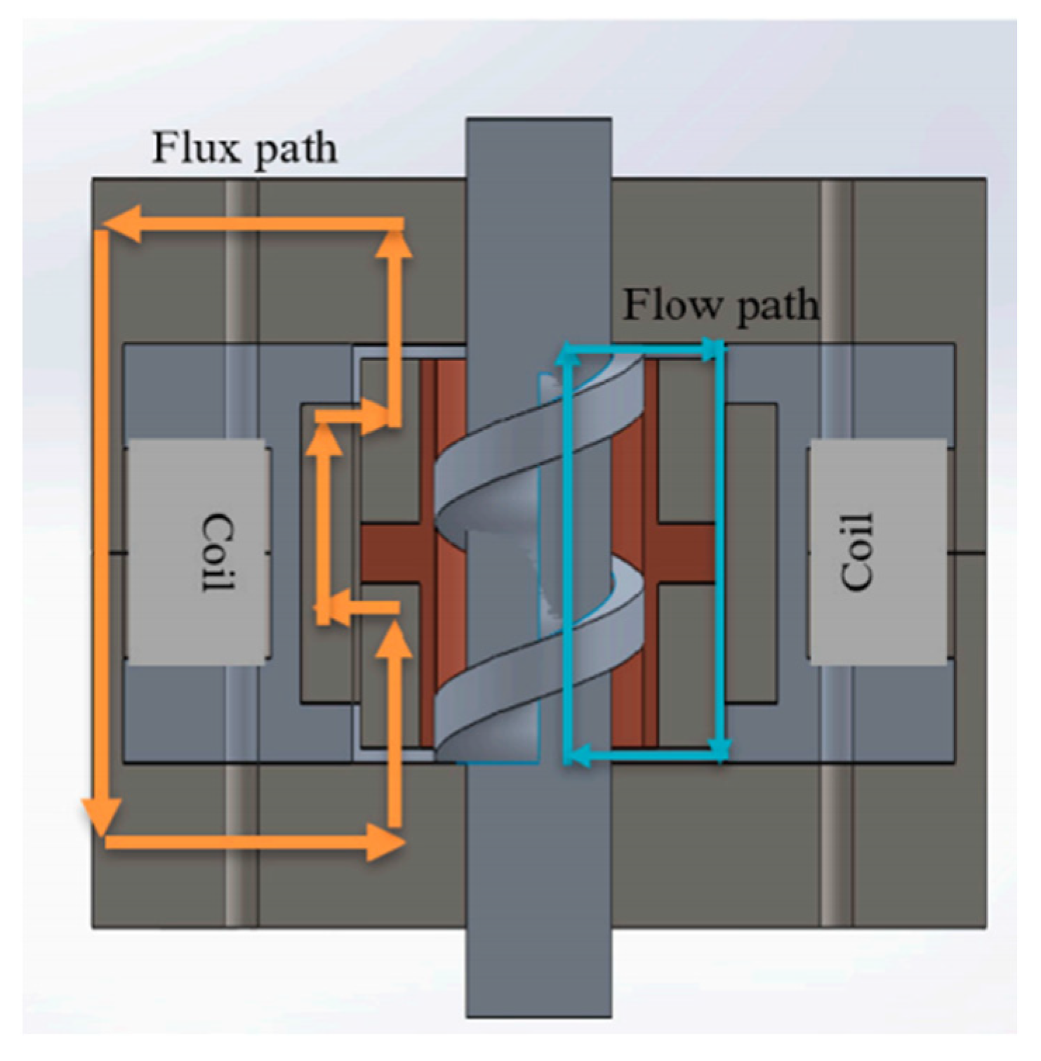
In addition, the piston rod’s length and the damper cylinder’s size limit the movement stroke of the piston. Recent research has utilized a new internal damping adjustment structure instead of the usual piston structure to eliminate the limit, allowing for a compact damper structure. Yu et al. [
40,
41] developed a spiral-flow rotating MRD with an optimized flux path, as shown in
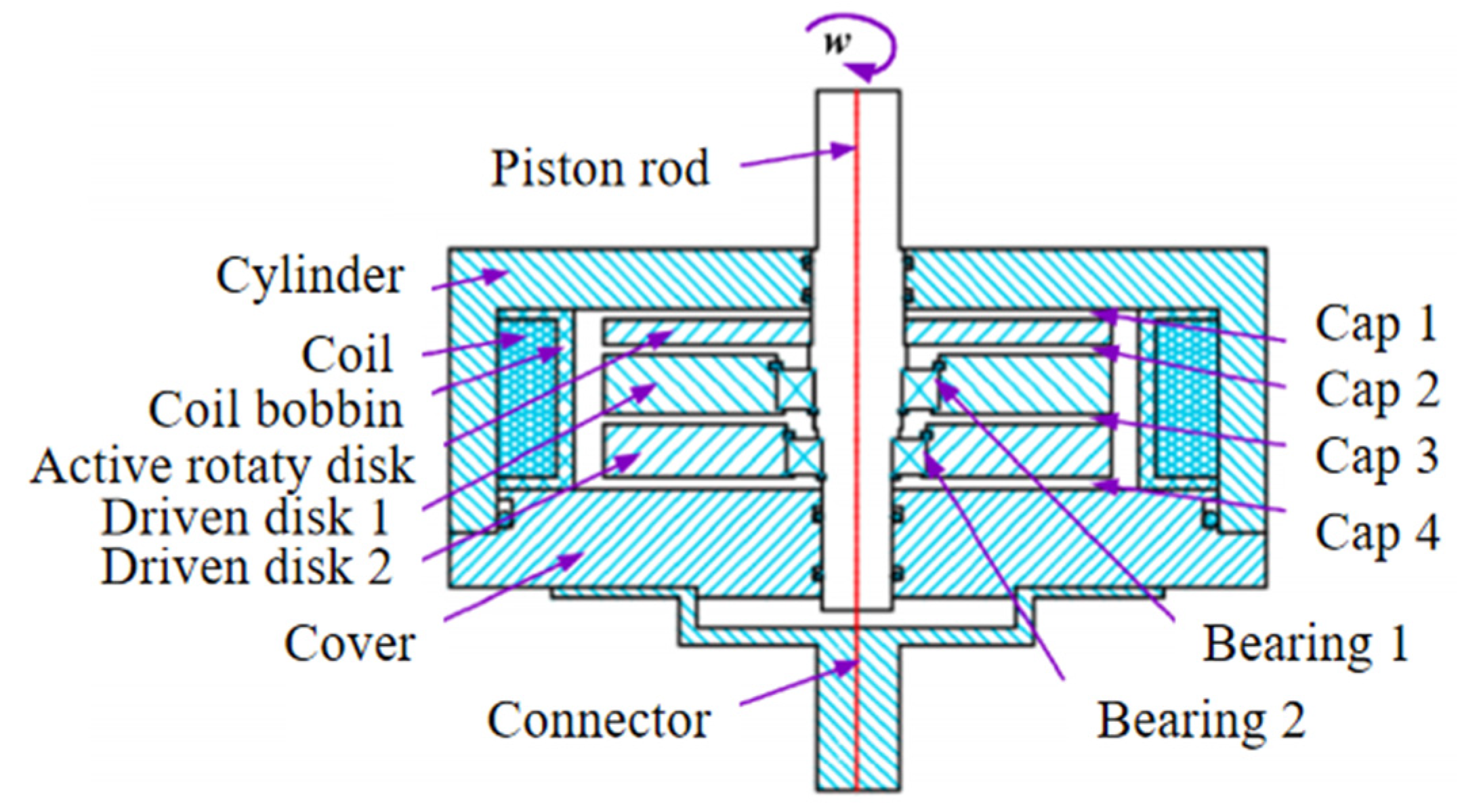
Figure 5. The inner cylinder of it consists of a conductive ring and a non-magnetic conductive ring, and the maximum torque increases from 0.15 N*m to 17 N*m when the current increases from 0 to 4 A, providing better magnetic field distribution, higher torque, and dynamic adjustment range compared to previous dampers. To ensure significant angular variable stiffness of the MRD output, Yu et al. [
42] proposed a new compact rotating MRD with variable damping and stiffness containing two drive discs and one active rotating disc, as shown in
Figure 6. They compared those with one drive disc and no drive disc, showing that the dampers have greater angular controllable stiffness.
Yu et al. [
43] prepared a shear-thickening MRF with a shear-thickening effect and magnetorheological effect, and designed a magnetic rate-controlled stage damper based on it. The central working part consists of the main piston and an auxiliary piston. The main piston has the function of shock resistance and energy dissipation; the auxiliary piston consists of permanent magnets and coils, which can realize energy dissipation of continuous variable damping. The dampers have been tested and proven to have an adjustable output range of 192.8–250.2 KN at large displacements and a flexible damping force range of approximately 1.3. They are suitable for various vibration excitation environments and resist shock energy dissipation. Elsaady et al. [
44] have proposed a piston design to enhance the magnetic properties of MRDs, mainly by improving the piston fluid region and the type of piston magnetic material.The piston consists of four magnetic coils connected in parallel, separated by five magnetic spacers made of Vacoflux-50, wound on a non-magnetic cartridge tube made of nylon-66 and surrounded by an isolator made of the same material. The piston rod is fitted with a magnetic core, also made of Vacoflux-50, with a damping channel between the core’s outer surface and the magnetic spacer. The improved design proposed in this study results in a significant increase in the magnetic field and fluid yield stress, a 50% increase in maximum damping force, and a high magnetic field at low input currents. It is suitable for the development of large MRDs ideal for higher loads.
In addition to innovative designs for piston structures, some researches based on general piston structures use optimizing techniques and tools to optimize the shape, dimensions, etc. Nie et al. [
45] investigated the influence of the form of the piston slot and the magnetic insulators at the ends of the piston on their operating performance. The MRD with chamfered piston slot edges and the magnetic insulators’ inclined edges had better damping force and dynamic range by simulation analysis. Optimizing the piston slot’s boundaries could reduce the magnetic circuit’s magnetic flux density and increase the working gap. The optimized damping force and dynamic range increased by 12.7% and 12%, respectively, and the structural volume reduced to 34.6%. Based on the double-ended MRD piston prototype, Gao et al. [
46] optimized the piston shape using the Bezier, one of the typical parametric curves. The transition between the front and rear piston heads and the intermediate piston in the prototype is not smooth at right angles, resulting in flux loss and reduced flux density in the ring gap. That significantly reduces the output damping force; the optimized piston can successfully solve the problem of regional magnetic saturation in the transition between the front and rear piston and the intermediate piston. The regional magnetic saturation in the transition area between the front and rear pistons and the intermediate piston can be successfully solved, resulting in a greater flux density in the ring gap and a more excellent controllable damping force range than the pre-optimized piston. Devikiran et al. [
47] designed a single-tube shear mode MRD for a two-wheeled vehicle. The piston size was optimized using the optimizing function ‘Optimization Toolbox’ of MATLAB to achieve an extended dynamic range and high damping force. However, they did not specify the particularities of the design of this damper structure for a two-wheeled vehicle. Hu et al. [
48] used a multi-objective genetic algorithm to optimize the critical structural parameters of a built-in double-ended MRD, resulting in a 43% reduction in power consumption and a 30% increase in the damping force of the MRD. This multi-objective optimization method, which maximizes the output damping force at low power consumption and minimizes the piston volume, was shown to provide new ideas for optimizing other dampers. Yoon et al. [
49] proposed a new core model that considers gap edge effects and B-H curve nonlinearity to give an accurate model for MRD core design, producing high controllable forces over a wide dynamic range without using the finite element method. Patel et al. [
50] developed a MRD for washing machine applications, using a generalized, simplified gradient (GRG) and grey relational analysis (GRA) optimization techniques for shear MRD design parameters (e.g., magnetic coil height, width, piston path radius, and optimum fluid volume). The method had a significant effect on reducing the cost of the damper.
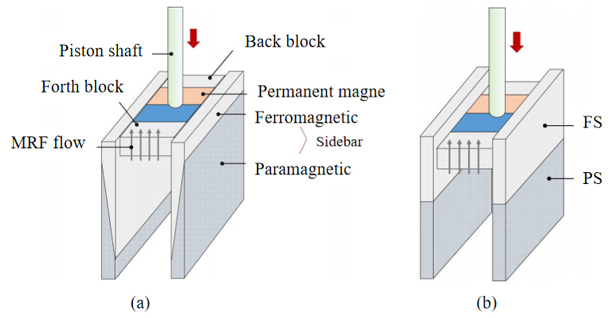
Lee et al. [
51,
52] designed a new permanent magnet-based MRD that uses two materials with different reluctances to provide flux dispersion in two magnetic circuits, as shown in
Figure 7. The MRD achieves a controlled damping force through the motion of the permanent magnet piston rather than through the magnitude of the input coil current. However, the response time is relatively slow compared to MRDs using electromagnetic coils. Building on previous research, the triangular cylinder was replaced by a rectangular column to achieve a stepped input response of the damping force based on switching state logic. They carried out experimental tests to measure the response time of the damper by considering three influencing factors: the material of the magnetic circuit, the magnitude of change in the damping force, and the excitation frequency of the piston. The results show that the damper has a faster-than-normal shortening response time and is suitable for specific applications where a fast response time of the damping force is required.
3.3. Damping Channel Improvement
The damping channel is a crucial design part of the MRD. The magnetorheological effect of the MRF in the damping channel generates damping forces, so the length and the width of the damping channel and the damping channel are essential factors affecting its damping performance. Generally, the smaller the damping channel width and the longer the damping channel length, the greater the damping force. The structure’s size and the piston’s stroke limit conventional damping channels’ length. Researchers should design the most extended damping channel while limiting the damper size to achieve a more extensive range of adjustable damping forces.
There is a problem of limited axial dimensions and short damping channels in general MRD. Hu et al. [
53] developed a new MRD with tandem flow channels, as shown in
Figure 8a, which obtained a more significant damping force by increasing the radial dimension. The results showed that the damping force of the MRD developed was 1.6 times the expected damping force, with high vibration control capability and good mechanical properties. Wang et al. [
54] proposed an MRD with a double-folded valve, where the MRF chamber is set in the spool, reducing the volume of MRF used and significantly shortening the overall axial dimension of the damper compared to the conventional annular valve. Satria et al. [
55] proposed a flow-type rotating MRD with a serpentine flux path without increasing the volume of the damper, thus increasing the output damping torque by optimizing the magnetic field density and the active area of the MRF. The output damping torque density varies from 42.18 at 0 rpm to 40,518.96 at 20 rpm, and the damper size can not limit it. Hu Guoliang et al. [
56] proposed an internal valve MRD. They replaced its piston head with a hybrid flow MR valve, mainly consisting of a positioning disc, a damping disc, and a coil assembly to form a winding, meandering damping channel. This structure can extend the damping channel’s length without increasing the damper’s outer dimensions, thus significantly increasing the output damping force. When the current is 1.2 A, the output damping force is up to 7.521 KN, with a damping adjustment factor of up to 9.7 and a wide damping adjustment range. Maharani et al. [
57] conducted an experimental mathematical simulation study of an MRD with an annular-radial gap on a valve using a single-tube flow valve with an annular-radial gap. The results of the study of the energy dissipation and the equivalent damping coefficient for the excitation amplitude and current input are that the higher the excitation amplitude of the current input, the higher the energy dissipation, while the value of the equivalent damping coefficient decreases. Haonan et al. [
58] designed a hybrid flow valve MRD, as shown in
Figure 8b. The damper fluid flow channel inside the excitation coil consists of four axial circular flow channels and two radial disc flow channels in series. The MR effect occurs between the fixed flat plates inside the piston head when the magnetic field is applied, and the output damping force of this damper can reach 59.4 KN when the applied current is 2 A. Its damping force adjustable range increases from 1 to 44.1374, effectively increasing the magnetic field utilization and producing good damping performance within the volume limits.
To provide adequate damping torque performance for the suspension of heavy-tracked vehicles, Wei et al. [
59] designed a new high-torque rotating MRD with parallel plate runners. They apply a compact parallel plate channel MR valve and design the spool perpendicular to the runner direction. The design can change the coil recess depth to adjust the non-magnetic field region and improve torque manageability, but its operating temperature will increase quickly. Hu et al. [
60] designed an MRD that could extend the effective damping channel without increasing the overall external structural dimensions of the damper. The new damping channel consisted of four axial circular flows divided by an inner sleeve and distributed inside and outside. When loaded with 1.1 A, the output damping force of this damper increased by 32.3% compared to that before optimization.
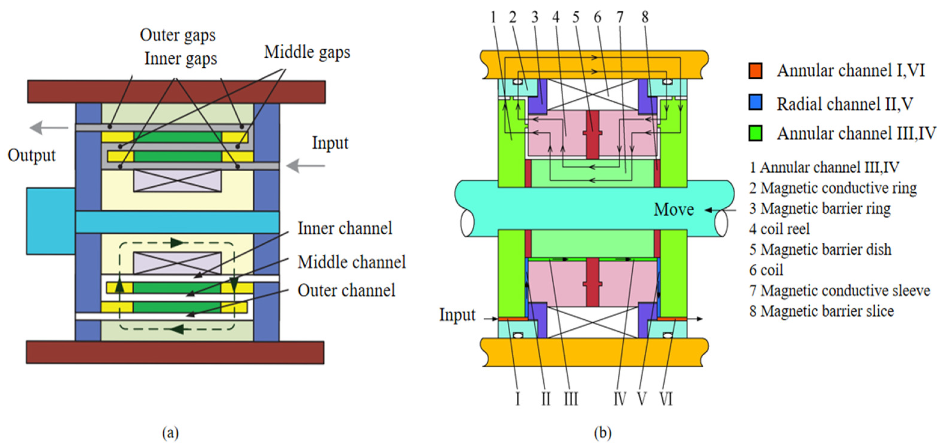
To address the influence of the damping gap width on the adjustable damping force, the adjustable gap MRD not only controls the amount of output damping force by current but also changes the size of the damping gap to adjust the structural parameters of the damper. Deng et al. [
61] designed an MRD with a tapered damping channel and proposed a time-frequency optimization scheme based on a vehicle dynamics model. The optimized MRD showed significant damping effects and improved vehicle performance. Still, they did not clarify the design reasons for the tapered damping channel and its advantages over the generally shaped damping channel. Hu et al. [
62,
63] developed a new MRD with an enhanced effective gap length by compactly integrating a tapered fluid channel into an annular fluid channel, as shown in
Figure 9. The width of the tapered gap can be continuously adjusted through the axial position of the control spool by a locking nut, achieving a double extension of the effective gap length. The experiments show that the damping force decreases with an increasing adjustable gap, and the dynamic range increases with an increasing adjustable gap under fixed current conditions. Compared to a conventional MRD with a fixed gap (dynamic range 9.6), the dynamic range of this damper can reach 33. It can not only adjust the damping force and dynamic content by current but also through changing the width of the tapered gap, improving the dynamic performance of the damper.
Xi et al. [
64] proposed a new MRD based on an axially variable damping gap. It uses a conical working chamber to vary the gap size at different piston positions under a constant excitation current to achieve a continuous output of the damping force for the entire piston stroke, with a buffering efficiency of over 90% under the design conditions. Still, direct shocks occur after the piston stroke reaches its maximum due to the small damping force at low currents.
As
Figure 10 shows, Zheng et al. [
65] designed a novel multi-coil MRD with a variable resistance gap. The surface of the piston head was a slope, meaning that the resistance gap’s thickness changes when the MR fluid flows. Its four coils have individual exciting currents. The novel variable gap MRD enlarges the maximum damping force and the dynamic ratio.
3.4. Summary of this Section
Based on the primary working components of the internal MRDs, this subsection provides an overview of the new structure of the internal MRD in terms of the coils, pistons, and damping channels. To improve the problems of poor utilization of the magnetic field and poor sealing caused by the coils inside the working chamber, researchers have improved the number of coils and coil arrangement and developed new structures such as multiple coils and separation of coils from the piston. Recent research focuses on enhancing the performance and increasing the output damping force despite the size limitations of the damper by adding non-magnetized channels to the piston, innovating the piston shape, and optimizing the piston shape with optimization tools. To extend the damping channels with a close damper structure, the new technical director will design serpentine meandering flow channels for the piston axially and adjustable damping gap widths for the radial direction, thus achieving an extensive range of elastic damping forces.
4. New Structure of Bypass MRD
The most important aspect of the bypass MRD is the design of the bypass magnetic core. The current research applications mainly use bypass MR valves. There are four types of bypass MRDs: single-tube single-ended, single-tube double-ended, double-tube single-ended, and double-tube double-ended, according to the number of cylinder barrels. The structural development of bypass MRDs organized in this way has been reviewed by Aziz et al. [
66] This section will overview recent structural developments in bypass MRDs for bypass magnetic cores (bypass MR valves).
MR valves consist of a flow channel between a pair of magnetic poles, with the differential pressure controlled by the applied magnetic field, and are simple, compact, reliable, and have no moving parts.
Figure 11 shows a typical MR valve structure. The MR valve mainly comprises an excitation coil, a spool, a valve body, and an end cap [
67]. When the piston moves, the MRF enters the main cylinder’s bypass MR valve from the liquid storage chamber. Under the action of the magnetic field of the solenoid coil in the valve, it flows through the internal working channel of the valve back to the main cylinder, generating a controlled damping force according to the operational characteristics of the fluid.
Based on the latest research results, the leading advanced structures of bypass MRD and bypass MR valve will be introduced from two aspects: optimization of working channel geometry and overall layout optimization. Designers should consider several parameters such as stroke length, air gap thickness, valve size, coil turns, and external current to increase the higher damping force and controllable range of the bypass MR valve. Based on these design parameters, MR valves improve the operating performance by optimizing the magnetic supply system, increasing the valve size, and increasing the effective fluid passage length in the valve.
4.1. Optimization of Working Channel Geometry
Early working gaps for bypass MR valves were annular gaps and radial gaps. Recent research has found that combined annular-radial working channels have a longer effective working length than a single annular channel, allowing bypass MRDs to have greater adjustable damping forces. A comparison of the geometric layout of the three bypass MR valves is shown in
Table 2.
Ai et al. [
71] designed a MR valve with both annular and radial fluid flow resistance channels, as shown in
Figure 12a. The efficiency of the MR valve with disc-type fluid resistance channels was better than that with annular fluid resistance channels at the same flux density and outer radius, and the annular-disc gap could significantly improve the efficiency of the MR valve. Nguyen et al. [
72] proposed an optimization procedure based on the finite element method to determine the optimal structure and geometry of MR valves of different configurations for a specific volume. It shows that the annular-radial type MR valve has better pressure drop with optimized design parameters compared to the conventional annular valve. Based on this, Wang et al. [
73] experimentally proved the correctness of the mathematical model. They verified that the fluid gap pressure drop with the annular radial is more significant than that of the annular flow gap. They concluded that a MR valve with a radial flow gap could achieve higher efficiency and more excellent controllable range than an annular flow gap to a certain extent. Imaduddin et al. [
74] proposed a compact MR valve, as shown in
Figure 12b, consisting of multiple curved flow channels formed by annular and radial gaps to extend the flow length of the MRF, thereby increasing the effective area. They further designed a MR valve with a curved flow pat, formed by a combination of multiple annular, radial, and orifice flow paths to increase the effective area and allow for miniaturization of the valve.
Based on the winding flux path MR valve designed by Alkan et al. [
75], Fatah et al. [
76] led the magnetic flux into the annular gap of the valve alternately through magnetic and non-magnetic materials to increase the effective area of the valve. It helps to increase the pressure drop across the valve further. Hitchcock et al. [
77] proposed a novel bypass fail-safe MRD. It achieves fail-safe characteristics by selecting an appropriate flow path geometry to obtain the minimum viscous damping force required for non-operational conditions. The damper can produce a considerable dynamic adjustment range. Hu et al. [
78] developed a MR bypass valve with ferromagnetic beads. Its main feature is the spherical ferromagnetic beads randomly filled inside a hollow non-magnetic stainless steel tube. They form a narrow, randomly oriented, curved damping channel, significantly increasing the length of the flow channel. The coil is wound around the valve outside, and the heat generated by the solenoid valve resistance does not cause the MRF to heat up and fail.
4.2. Overall Layout Optimization
Based on the magnetorheological bypass valve, the bypass MRD has also designed its overall layouts such as the number of cylinders, the bypass connection method, and the installation position of the bypass valve to achieve better working performance.
Wang [
31] proposed a modular disk-based magnetorheological bypass valve for commercial seismic applications, with the disk placed between two fixed parallel plates with radial flow channels. The MR valve is compact, efficient, and can flexibly apply to different sizes of bypass MRDs. Dong et al. [
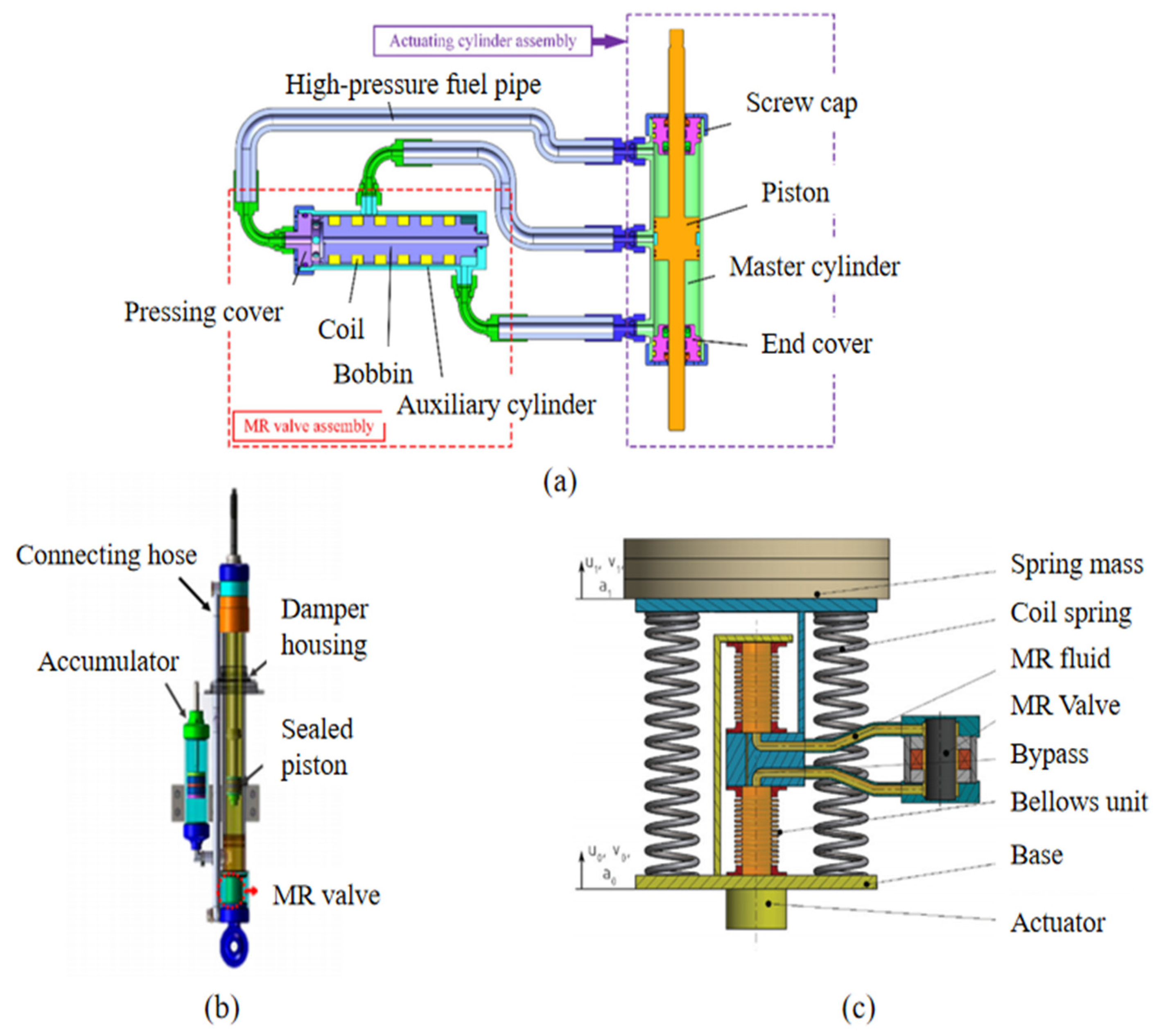
79] designed a new single-end external valve mode parallel gap damper. Its main feature is a check valve. When the piston stretch, the two piston check valves close, and the bottom cavity check valve opens. Meanwhile, MRF in the right cavity flows through the annulus into the MR bypass valve and then into the left hole. It has high efficiency, high sensitivity, no sink ability, and a more significant damping force. Jiang et al. [
80] designed a multi-channel bypass MRD with selectable performance parameters, as shown in
Figure 13a. It connects with three sets of channels with different working lengths, and the structure can adjust the variable damping by current and the variation of MRD performance parameters by selecting other channels. The damper has good environmental adaptability but will cause high friction due to mechanical movement.
Zhang et al. [
81] proposed a novel MR valve bypass MRD with a three-cylinder scheme of the reservoir, working and intermediate cylinders, and a magnetorheological bypass valve based on the squeeze mode mounted on the sidewall. The damper has superior dynamic performance, compact structure, low energy consumption, and cost, and it is suitable for small buses. Idris et al. [
82] proposed a new bypass MRD with a serpentine MR valve in a concentric design configuration. As shown in
Figure 13b, unlike the typical structure of bypass dampers, this serpentine valve is mounted in line with the cylinder shaft axis, reducing the extra space it requires, with the advantages of compact dimensions, easy assembly, and simple maintenance. Still, the performance of this MRD is affected by seal friction at higher piston speeds.
To eliminate the friction caused by the piston seal when the fluid flow in the cylinder barrel, Macháček et al. [
83] designed flexible metal bellows with a static seal to replace the piston and piston rod in a conventional MRD.
Figure 13c shows that this bypass MRD replaces the piston unit with a bellows unit. With adaptive-passive damping control, the damping performance is improved over the entire frequency range, enhancing the quality of the semi-active suspension system.
Figure 13.
Bypass MRDs with overall layout optimization: (
a) Multi-channel bypass MRD [
80]. (
b) Concentric serpentine flux valve MRD [
82]. (
c) Flexible metal bellows MRD [
83].
Figure 13.
Bypass MRDs with overall layout optimization: (
a) Multi-channel bypass MRD [
80]. (
b) Concentric serpentine flux valve MRD [
82]. (
c) Flexible metal bellows MRD [
83].
4.3. Summary of This Section
Based on the latest research results of the bypass MRD, this subsection introduces the structural innovation of the magnetorheological bypass valve in the bypass MRD, mainly regarding the damping channel and the overall layout. By comparing different geometric arrangements of the working channels, the results show that the combined working channels have better working performance. In addition, the new bypass MRD structure focuses on improving the overall layout of the number of cylinder barrels, bypass connections, bypass valve mounting positions, etc. Using multiple channels and concentric and other structural designs optimizes the damper’s performance and makes the bypass MRD more compact.
5. New Hybrid MRD
5.1. Hybrid Working Mode Type
The performance of MRFs in a single mode of operation is sometimes insufficient to meet the design requirements, so the hybrid mode of operation MRD is gradually attracting more and more attention from researchers. As can be seen from
Table 1, the shear mode MRD magnetic circuit design is simple, but the damping force generated is negligible. Flow mode MRD generates a sizeable damping force, but the magnetic circuit design is complex. Squeeze mode MRD can cause a considerable damping force, but the working displacement is small, only suitable for low speed and a small range of vibration area. Yazid et al. [
84] studied shear and squeeze dual-mode MRDs, and mixed-mode MRDs can produce higher damping forces than single-mode dampers.
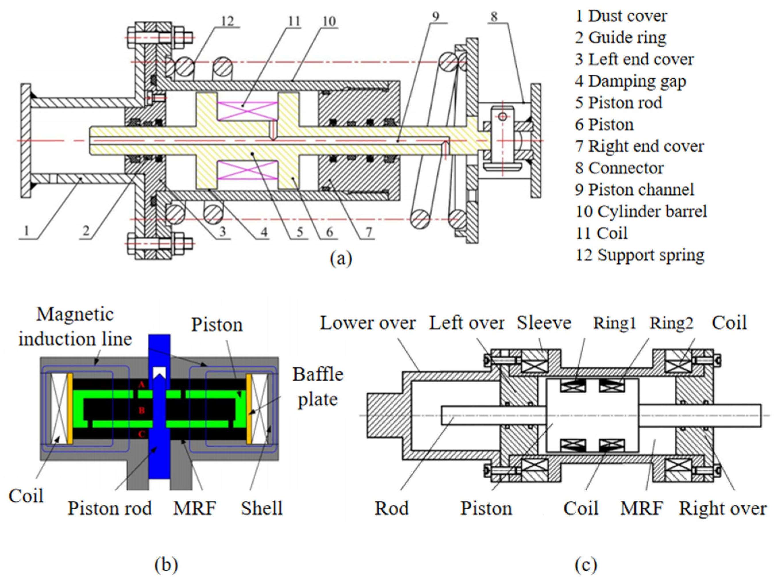
Figure 14a shows that Wu et al. [
85] designed a shear-flow MRD. It operates in both flow and shear modes to reduce resonance phenomena in a vibrating screen’s start-stop phase. It combines with a spring to form a new MR vibration isolator and has a much higher damping capacity than the traditional metal spring isolator, though at a higher cost.
As shown in
Figure 14b, Ruan et al. [
86] developed a new MRD with dual mode operation of the squeeze valve, mainly consisting of two parts, the valve part and the squeezing part. The squeezing part provides a more significant damping force, and the valve part both provides the damping force and promotes the flow of MRF and the redispersion of particles. This new damper suits low frequency and low amplitude vibration isolation. Chen Shumei et al. [
87] designed a shear-squeeze hybrid mode MRD.
Figure 14c shows that the main feature is configuring two coils at the piston and cylinder barrel each. When energizing different coils, the shear-squeeze hybrid mode MRD generates different operating modes. This hybrid damper improves the disadvantages of the small damping force of the shear valve type and the small working displacement of the squeeze type so that the damper has greater output damping force and higher power adjustable factor.
Many studies have shown that the performance of dampers in mixed mode is generally better than those in single mode. However, problems with complex structures, difficult magnetic circuit analysis, and high manufacturing costs remain. The design of a new MRD structure for mixed-mode operation should therefore meet the requirements of high damping force, simple magnetic circuit design, and wide adjustable range.
5.2. Hybrid Power Type
The general MRDs are powered by an excitation coil that generates a magnetic field to drive the MRF, and the coil cannot produce a stable magnetic field until the power is applied. Therefore, in the event of a power failure, it is dangerous to keep the damper in a low-damping state. Due to the MRF instability, it is prone to settle and affect the overall operation of the damper. Recent research has used permanent magnets and electromagnetic coils as a hybrid for the damper to improve MRF settling, prevent failures, and improve equipment safety.
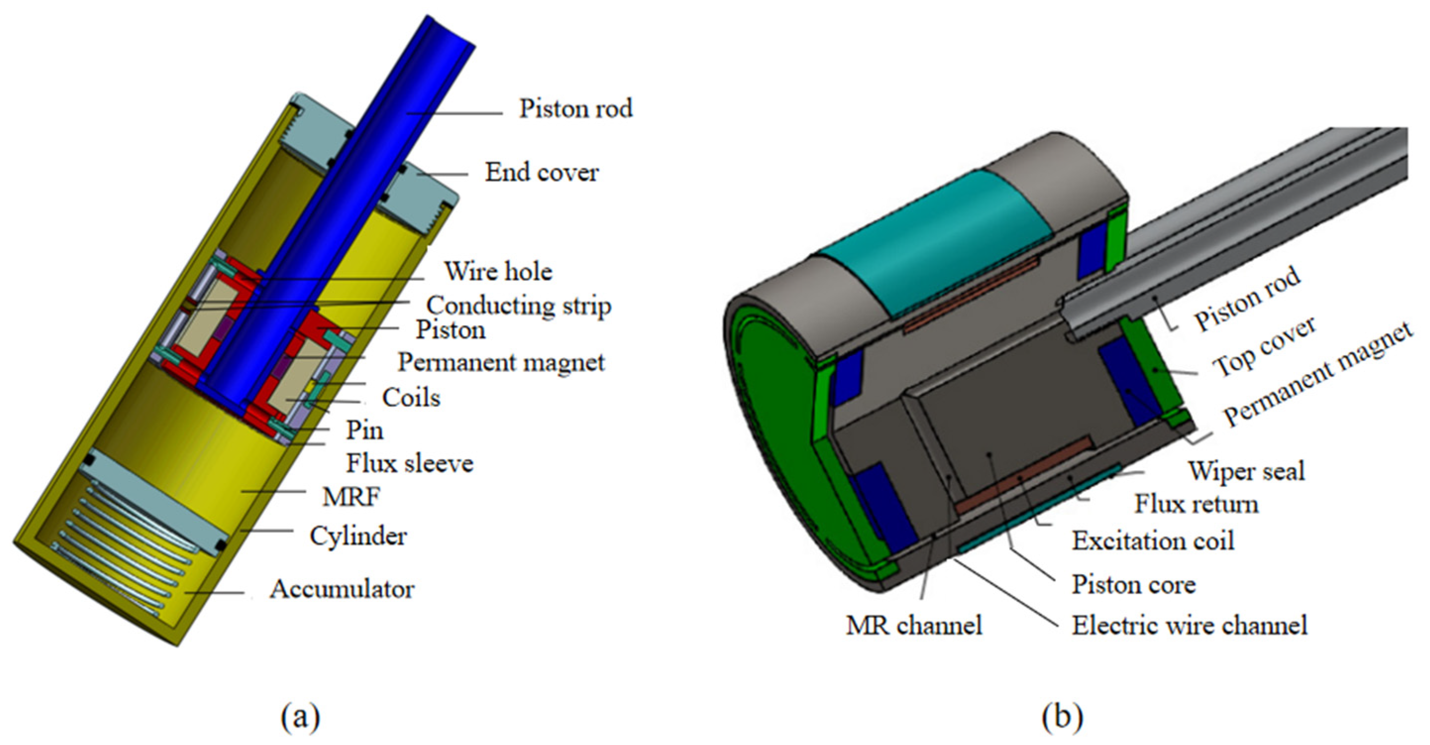
As shown in
Figure 15a, Huang et al. [
88] developed an MRD for improving and monitoring the settling stability of fluids. Permanent magnets between the upper and lower pistons generated a magnetic field when the coils were not operating. This design improved MRF settling stability and reduced the channel heat. MRF settling stability is enhanced by 19.6% compared to a conventional sealed environment. Jeniš et al. [
89] designed a fail-safe MRD with ring-shaped permanent magnets in the core. It simulated obtaining a fail-safe damping force of about 1/3 of the maximum damping force and a maximum power range of 8.5, satisfying the needs of the fail-safe and essential operation. Olivier et al. [
90] designed a new hybrid MRD, as shown in
Figure 15b, mainly consisting of two permanent magnets and an electromagnetic coil. It provides good ride quality and road-holding performance. Munyaneza et al. [
91] proposed a further MRD with both permanent magnets and electromagnetic coils to improve the damping force at a low current supply and to provide fault-weakening capability in case of electrical failure. In the off state, the two permanent magnets will generate an intense magnetic field in the ring gap for protection. When energized, the electromagnetic coils excite a greater damping force to improve passing smoothness for bumpy roads.
5.3. Hybrid Particular Part Type
MRDs are used as an actual application in practical vibration damping systems and are often combined with other components to meet the performance requirements of the damping system.
Nakano et al. [
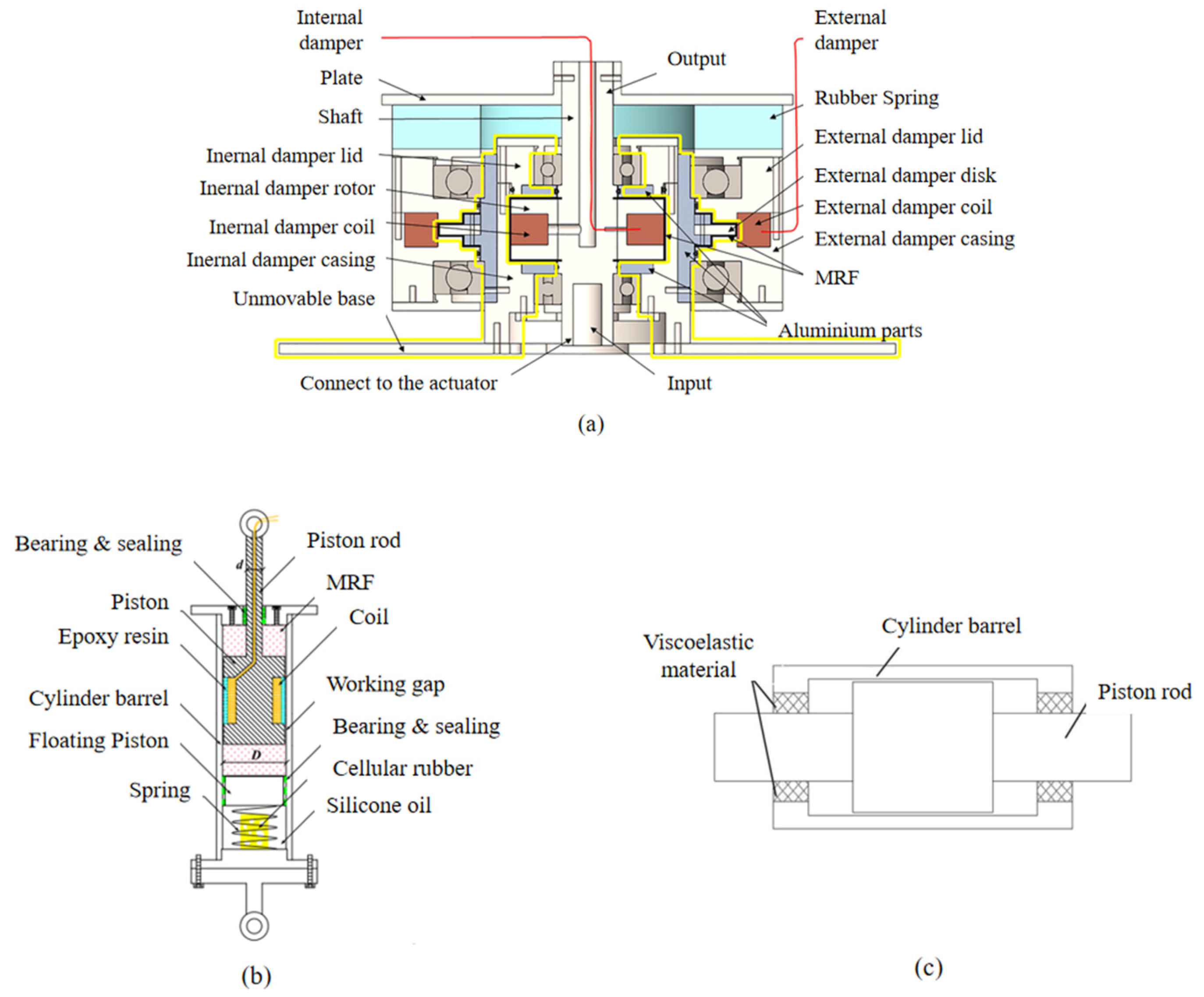
92] developed a small-scale seismic linear MRD. It mainly consists of a ball screw mechanism, a linear guide mechanism, and a rotating MRF porous composite brake, capable of converting the linear motion of the MRD (damping force) into the rotation of the brake (braking torque) with almost no transmission losses. Deng et al. [
93] designed a new rotary damper with variable stiffness and variable damping, as shown in
Figure 16a, consisting of an internal and external MRD (in series with a rubber spring) connected in parallel. Adjusting the internal damper current control, the damping variation, and adjusting the external damper current controls the stiffness, achieving independent control of damping and stiffness. However, the damper is not compact, and the damping adjustment range is limited at higher currents.
Sun et al. [
12] also proposed an MRD device with variable stiffness and damping, mainly consisting of two damping cylinders and two springs with different stiffnesses. Adjusting the current of the bottom damper controls the damping force, and the variable stiffness is regulated by the current of the top damper with the two springs. It is superior in improving ride comfort compared to passive suspension systems. Xu et al. [
94] proposed a new single-rod MRD with a combined volume compensator, as
Figure 16b shows, which consists mainly of springs, foam rubber, and silicone oil, allowing independent functions of spatial compensation and compensation forces, without relying on high initial pressures. The equivalent damping of the new MRD with this combined compensator decreases with increasing frequency to meet the vibration requirements of inclined ropes. The adjustment range is wide, especially at low frequencies and minor values, to meet the needs of civil construction vibration control. Du et al. [
95] designed a new MRD with thermal insulation, most notably by placing an insulating foil bubble insulation with low thermal conductivity between the solenoid coil and the cavity. It avoids rapid temperature rise during MRD operation, reducing the temperature growth rate of the MRF in the working area by 57.4% and allowing operation in all three modes, providing higher damping forces without expanding the size of the damper structure. Yao et al. [
96] designed a new metal foam MRD with porous metal foam glued to an internal working cylinder to store and release MRF. It has a long service life, no need for sealing, a low cost compared to sponge-based MRDs, and a longer response time.
Figure 16.
Hybrid MRDs with particular part type: (
a) New rotating MRD with variable stiffness and variable damping [
93]; (
b) single rod MRD with combined volume compensator [
94]; (
c) leak-proof MRD [
97].
Figure 16.
Hybrid MRDs with particular part type: (
a) New rotating MRD with variable stiffness and variable damping [
93]; (
b) single rod MRD with combined volume compensator [
94]; (
c) leak-proof MRD [
97].
Recent research often improved the sealing performance in combination with particular components to improve the sealing performance of MRDs and prevent leakage of MRFs that would reduce the life of the damper. Tu et al. [
97] designed a leak-proof MRD with a viscoelastic material inserted between the piston cylinder and the piston rod instead of the conventional O-ring. As
Figure 16c shows, there is no friction between the viscoelastic material and the piston rod, thus successfully replacing the dynamic seal with a static seal, extending the service life of this damper, and improving its engineering applicability. Jiang et al. [
98] proposed an innovative elastomeric MRD. The main feature is that two groups of elastomers are arranged on both sides of the piston to form a seal. The dampers were tested and found to be suitable for small amplitude vibration damping applications such as helicopter rotors, which have the advantages of controllability, excellent sealing, and compactness compared with traditional helicopter hysteresis dampers.
5.4. Summary of This Section
This section overviews three types of hybrid MRDs that offer superior operating performance to conventional dampers. The mixed mode of operation MRD combines the advantages of a single mode of operation with an improved damper channel structure for dual and multi-mode functions, depending on design requirements. The hybrid type is a mixture of permanent magnets and electromagnetic coils as dampers, which can improve the fail-safe capability and effectively improve the MRF settling problem. The hybrid particular component type MRD is a vibration damping system that combines dampers with other components such as ball screws, springs, and new sealing materials to meet the design requirements of specific engineering applications.
6. Latest Engineering Applications of MRD
MRDs were first applied in vehicle vibration reduction and building earthquake resistance and gradually developed in aerospace and ships. The latest research has applied MRDs to artificial limb systems, military equipment, etc.
MRDs are used in vibration-damping systems to achieve semi-active control and improve ride comfort and vehicle safety. The major global manufacturers of MRDs are BWI (Beijing West Industries) Group, LORD Corporation, Arus MR Tech, etc, with BWI Group having the largest market share in 2019 at 65.39%. Its main commercially available products are magnetorheological control suspension systems and magnetorheological powertrain mounts. It shows that MRD has been applied in a wide range of applications in vehicle engineering. As an MRD utilizes the effect of magnetorheological fluids, it is combined with a control system to form an easy-to-control and high-performance damping system. Recently research on the MRD vehicle vibration field mainly focuses on the semi-active control method of MRF. Many control methods are still immature, mainly including the latest research progress shown in
Table 3.
A typical application in the aerospace sector is its installation in aircraft landing gear systems and the incorporation of control theory to overcome the shortcomings of regular passive dampers with limited performance in different landing scenarios [
107]. Many recent studies have been carried out by modeling aircraft landing gear, designing suitable MRDs, and applying robust controllers [
108] and neural network controllers [
109] for vibration control and monitoring. However, most of the current research has focused on theoretical simulations, which are difficult to validate experimentally due to their models’ complexity and high cost. In addition to the aircraft landing gear, as shown in
Figure 17, Lin Zhan et al. [
110] designed a full-size rotor MRD structure. They carried out simulations and prototype experiments, which showed that the development of the prototype had a stable performance. Wang et al. [
111] proposed a new lunar lander with MRD whose damping force considered the coupled electromagnetic hydrodynamics of MRF under high-speed impact. As shown in
Figure 18, experiments demonstrated that the structure could apply to impact absorption as a variable damper. The lander with this MRD could adapt to various complex landing conditions.
MRDs are a relatively inexpensive semi-active device that is reliable, provides electrical fault protection, and is therefore widely used for seismic protection of buildings. Many studies have demonstrated the effectiveness of using MRDs for seismic control. However, a significant disadvantage of its application to building seismic resistance is its non-linear properties, including hysteresis. Recent research in the field of building seismic resistance has focused on the modeling and control of seismic dampers [
112]. Caterino et al. [
113] developed a MRD-based semi-active control technique for seismic protection of single-store precast reinforced concrete buildings. They proposed an innovative solution to reduce the effects of earthquakes on precast reinforced concrete structures, which significantly reduces the base bending moment caused by seismic action and controls lateral displacements to reduce induced damage to non-structural components. Ruanet [
114] al. designed a large-scale MRD to improve the performance of shear walls, as shown in
Figure 19. The test results showed that it has a stable working version under different working conditions, which can improve the energy dissipation capacity of shear walls and increase the stiffness and load-carrying capacity of shear walls.
Guo et al. [
115] used ABAQUS software to establish a finite element model of an external MRD high-strength reinforced concrete shear wall. They compared the test results to investigate the seismic performance of a high-strength reinforced concrete shear wall with external magnetorheological dampers. The more fantastic the damping force, the greater the specimen’s energy dissipation capacity and load-carrying capacity. Based on these findings, the efficiency and working performance of MRDs for seismic applications in buildings continue to improve, but they still face practical problems such as manufacturing difficulties, leakage of MRFs, and wear inside pistons and cylinders. The researchers will investigate challenges gradually in future seismic MRD applications.
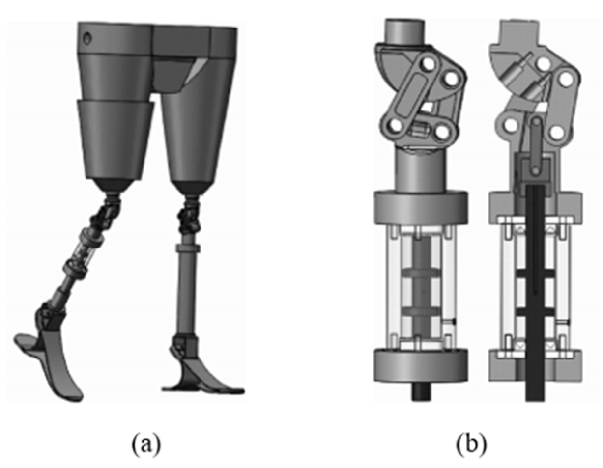
Some researchers also investigated using MRDs in prosthetic devices due to their fast response time, low power consumption, and high dynamic yield stress performance. In response to the problems of bulky size and the poor gait quality of existing prosthetic products, Liu Xuhui et al. [
116] combined a four-link mechanism with MRDs to design a magnetorheological damped prosthetic knee joint. They built a virtual prototype model of the lower limb prosthesis. They carried out a motion simulation of the lower limb prosthesis using SolidWorks Motion. The results showed that the gait characteristics of this lower limb prosthesis had good bionic properties driven by the joint angle curve. Based on this four-link mechanism magnetorheological damping prosthetic knee joint, as shown in
Figure 20, Jian Zhen et al. [
117] built an experimental test platform for joint motors. They carried out motion control research on lower limb prosthetic joint motors to achieve good results of joint motors in the following joint angle curve trajectories.
In addition, MRDs apply in the military equipment field. Still, due to the specificity of the military application environment, many studies are currently only in the simulation and experimental stage, and whether they can better cope with the changing operating conditions of the battlefield is still to be examined. Yao et al. [
23] summarized the research progress of MRF, including MRD in the military field. They pointed out their application products would develop into minimization, intelligence, and general standardization. The Nanjing University of Technology has made outstanding research results in the weapons industry and military technology field. Zhang Guang [
118] and Wang Ming [
119] have applied MRD to artillery suspension systems and continued to develop new technologies.
The most common practical applications in vehicle vibration damping systems and gradually maturing related technologies are introduced in this section. With the gradual development of MRD, many studies have applied it to various vibration control fields such as vehicle engineering, aerospace, building seismic, prosthetic systems, military, and other areas. Other applications in the field of vibration control have mainly focused on the laboratory test phase. The feasibility of future applications in various advanced fields has been confirmed to a certain extent by simulation analysis and prototype tests. The engineering applications of MRD still need to overcome the difficulties of immature smart fluid technology, high experimental costs, and complex practical working conditions. However, it still has a broad application prospect.
7. Conclusions
This paper provides an overview of the development of MRDs and their latest engineering applications and a more comprehensive summary of the basic structures and operating modes of MRDs in recent years. By understanding the status of MRD research and reviewing the latest structural advances in internal, bypass, and hybrid types, the main conclusions are as follows:
(1) The main directions of improvement for internal MRDs are to rationalize the number of coils and their arrangement in the damper, change the overall appearance of the piston or optimize its structure using mathematical tools, and extend the effective working length of the damping channel. These new structural studies have resulted in compact designs and improved magnetic field utilization, but inevitably increased manufacturing complexity and application costs.
(2) The bypass MRDs are mainly innovative in structure by optimizing the working channels’ geometric arrangement and the dampers’ overall layout. These improvements bring into play the advantages of an extensive dynamic adjustment range of the damping force and excellent flexibility. However, the disadvantage of the bypass type taking up a lot of space still needs further improvement.
(3) Hybrid MRDs improve the overall performance of the dampers by mixing the operating modes, magnetic field dynamics, and particular components based on the internal and bypass structures, considering the advantages of various MRDs, reducing the disadvantages of a single operating mode, improving the fail-safe capability, and meeting the vibration damping requirements of various engineering applications. However, current hybrid MRDs tend to have complex structural designs, high manufacturing costs, and low versatility.
(4) MRDs have been applied to vehicle engineering, aerospace, civil engineering, prosthetic systems, and defense industries. Accordingly, future MRD structures will develop to high magnetic field utilization, large damping, low power consumption, compact design, small volume, simple and low-cost manufacturing, good versatility, and intelligence.


