Article

Investigation on Polishing the Concave Surface of Zirconia Ceramics with Magnetic Compound Fluid Enhanced by Hydration Reaction

1
Faculty of Optoelectronic Manufacturing, Zhejiang Industry & Trade Vocational College, Wenzhou 325600, China
2
CCCC Second Harbor Engineering Co., Ltd., Wuhan 400430, China
3
Intelligent Manufacturing College, School of Wenzhou Polytechnic, Wenzhou 325035, China
4
College of Mechanical and Electrical Engineering, Wenzhou University, Wenzhou 325035, China
*
Author to whom correspondence should be addressed.
Magnetochemistry 2023, 9(3), 74; https://doi.org/10.3390/magnetochemistry9030074
Submission received: 7 December 2022 / Revised: 20 February 2023 / Accepted: 1 March 2023 / Published: 3 March 2023
(This article belongs to the Special Issue Advanced Applications of Magnetic Field-Responsive Fluid)

Abstract

:
Zirconia ceramics are prominent engineering materials and are widely used in computers, consumer electronics, and the fifth-generation communication industry. However, zirconia ceramics are a typical hard-to-cut material, and the product structures are more complex as the demanding on the industry increases. In this case, the polishing efficiency should be improved for meeting these requirements. To overcome the problem of polishing concave surfaces of zirconia ceramics, a small polishing tool with a magnetic compound fluid (MCF) was invented. The effect of the polishing parameters on the surface roughness and material removal rate was analyzed by an L9(33) orthogonal experiment. The weight ratio of the parameters was also studied based on the experimental results. With the combination of chemical and mechanical functions, the polishing characteristics were further examined. Based on the soaking experiments, the material removal mechanism is discussed. The results are as follows: (1) the optimal polishing parameters were the revolution speed of the MCF carrier nc of 400 rpm, the working gap h of 0.1 mm, the CIP size D of 5 μm for better surface roughness, the revolution speed of the MCF carrier nc of 400 rpm, the working gap h of 0.1 mm, and the CIP size D of 7 μm for a higher material removal rate. The impact degrees on surface roughness and material removal rate were a revolution speed of the MCF carrier of 54% > working gap of 31%> CIP size of 15% and working gap of 40% > revolution speed of the MCF carrier of 32% > and CIP size of 18%, respectively. (2) Surface roughness was rapidly reduced in the first 20 min and tended to be stable in the last 10 min of polishing. A circular polished area was observed on the flat workpiece for studying the typical material removal curve, and the deepest point was found at the fringe of the material removal curve. The concave workpiece was polished successfully, and the best surface roughness Ra reached 1 nm and 1.2 nm. (3) A pH = 10 with a sodium hydroxide (NaOH) solution has a greater performance in hardness reduction. The chemical and mechanical functions were combined to remove material to enhance the polishing efficiency. All in all, the proposed polishing method with a combination of a small MCF polishing tool and hydration reaction was effective for polishing zirconia ceramics.

1. Introduction

There are several commonly used ceramics, such as zirconium oxide, silicon nitride, and aluminium oxide, which have outstanding chemical and physical properties, such as high hardness, high strength, high toughness, and corrosion resistance [1]. However, zirconium oxide has higher abrasive resistance, toughness, and service temperature than silicon nitride and aluminium oxide. Generally speaking, structural products made of zirconia ceramics, such as the outer shells of smart devices, have better cost performance from the viewpoint of computers, consumer electronics, and the fifth-generation communication industry [2]. With the development of modern industries, the demand for precision zirconia ceramics components with concave surfaces is increasing gradually. To gain product popularity, these products always require higher surface quality to enhance the user experience [3].
Traditional processing methods of zirconia ceramics (turning, milling, grinding) have many limitations, such as low efficiency and unavoidable processing damage, in obtaining satisfactory surface quality [4,5,6,7]. Therefore, to improve surface quality, sandblasting, acid etching, and polishing are often used for post-surface treatment [8,9,10]. However, sandblasting and acid etching are apt to contaminate the workpiece surfaces or change the physical and chemical properties on the workpiece surfaces. Polishing can effectively improve the surface quality to attain a clean surface and remove surface and subsurface damage caused by previous processing. At present, the commonly used polishing methods for zirconia ceramics include abrasive polishing and chemical–mechanical polishing. Li et al. prepared an abrasive slurry with ultrasonic atomization to polish zirconia and obtained a surface roughness of Ra = 1.36 nm and a material removal rate of 272.44 nm/h [11]. Wang et al. polished zirconia by CMP that included sodium-stabilized silica sol (80 nm diameter) to obtain a material removal rate of 75 nm/min [12]. However, these methods still result in scratches and subsurface damage. As a proven technique, magnetic field-assisted polishing is effective in achieving a flexible polishing tool and inducing a controllable material removal rate on the microscale [13,14], which results in better surface quality than any other polishing method. In the absence of a magnetic field, the magnetic particles and abrasive particles are suspended in the magnetorheological fluid (MRF) slurry, showing Newtonian fluid characteristics. Once an external magnetic field is applied, the magnetorheological fluid slurry immediately turns the liquid state into a solid-like state and behaves like a Bingham fluid. The viscosity and stiffness change because the magnetic particles were magnetized to form magnetic chains in the magnetic field, and the abrasive particles move far away from the magnetic field [15]. Then, a magnetic flexible polishing tool is generated. Guo et al. proposed an enhanced magnetic polishing method with a larger polishing area to polish zirconia, and the surface roughness Ra reached 2.8 nm [16]. Ling et al. polished zirconia ceramics with MCF assisted by ultrasonic vibration, and a supersmooth surface was obtained [17]. Lei combined magnetorheological fluid with the shear thickening method to polish zirconia, and a surface roughness of Sa = 13.2 nm and a material removal rate of 5.96 μm/h were obtained [18]. These studies demonstrate that the magnetic field-assisted polishing method performed well in polishing zirconia ceramics due to its extremely low normal force and very small removal volume. However, the poor dispersibility of carbon iron particles within magnetorheological fluid went against nanoprecision surface polishing. To enhance the properties of magnetorheological fluids, Shimada et al. mixed microsized carbon iron particles, cellulose, and nanosized Fe3O4 together to obtain a magnetic compound fluid, which showed a higher dispersion and higher magnetic response viscosity than magnetorheological fluids [19]. Based on the invented fluid, Wu et al. proposed a new method for surface finishing with a disc magnet that was eccentrically located on the revolution axis [20]. Feng proposed a ring-shaped polishing tool with a magnetic compound fluid and studied its basic performance on convex surfaces [21]. However, due to the limitation of the mechanical structure, these conventional methods cannot meet the polishing requirements on concave surfaces. Therefore, Feng et al. proposed a small polishing tool with a magnetic compound fluid for polishing concave surfaces [22]. The polishing tool can maintain high efficiency in tool shape recovery by a concentrically located magnet that is magnetized radially. It was verified that this method can result in nanoscale surface roughness on concave surfaces made of optic glass. Although the small polishing tool was reasonable for polishing concave surfaces, the polishing efficiency was still low when polishing hard-to-cut material with a concave surface because the hardness of the workpiece surface was close to abrasive particles. In this case, to enhance the material removal rate when polishing zirconia ceramics with concave surfaces, the hydration reaction between zirconia ceramic and an alkaline solution was considered to combine with a small MCF polishing tool for the first time, which can reduce the workpiece surface hardness and the softened material can then be removed easily by the abrasive particles.
To apply a small MCF polishing tool with an alkaline solution to polish the concave surface of zirconia ceramics, this paper will analyze the influence law and weight of the process parameters on surface roughness and the material removal rate, optimize the process parameters, explore the process characteristics, and analyze the material removal mechanism of this method deeply.

2. Method

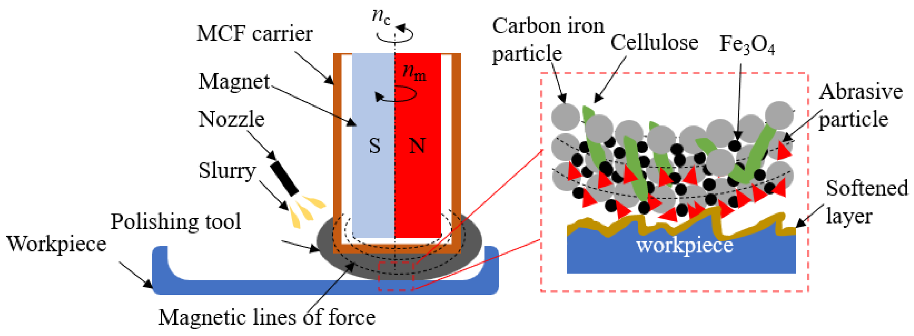
2.1. Polishing Principle

A schematic drawing of the polishing concave surface used in this work is shown in Figure 1. By using a small polishing tool with a magnetic compound fluid (MCF), a concave surface made of zirconia ceramics was polished by scanning the workpiece surface. The radius-magnetized magnet was used and located concentrically to the nonmagnetic shell (MCF carrier), which was used for carrying the MCF slurry. The magnet and MCF carrier can revolve independently in revolution speeds nc and nm around the revolution axis of the MCF carrier. Therefore, a dynamic magnetic field is formed by the continuous alteration in the magnetic lines of forces around the surroundings of the MCF carrier. Then, when a certain amount of MCF slurry is attached to the outer surface of the MCF carrier, the polishing tool will be obtained and has the capacity to recover the tool shape under the dynamic magnetic field. Once the polishing tool touched the workpiece surface, the tool shape was changed according to the appearance of the workpiece surface. Moreover, once the working portion of the polishing tool rotated out of the workpiece surface, the tool shape was recovered immediately. Therefore, polishing uniformity on arbitrary workpiece surfaces was ensured. Meanwhile, an abrasive particle slurry was dropped into the working area. By the chemical action between the slurry and workpiece, the material hardness on the workpiece surface was reduced for easy removal, leading to an enhancement in polishing efficiency. The typical material removal principle is explained in the right portion of Figure 1. Chain-shaped clusters were formed by the ferric particles (carbon iron particles and Fe3O4), which align along the magnetic flux lines. Fe3O4 particles were attracted between the carbon iron particles, leading to an enhancement in the attraction area of the carbon iron particles, which can strengthen the toughness of a single cluster. These α-celluloses intersperse into the clusters to improve the toughness of the clusters. Due to the combined action of the magnetic levitation force and gravity, the abrasive particles reached the workpiece surface and were gripped by the clusters. Due to the movement of the polishing tool, the abrasive particles gain relative movement to the workpiece surface. The material is softened by a chemical treatment and thereby removed by the microcutting action of the abrasive particles. Furthermore, due to the dynamic magnetic field, the magnetic line of forces at the MCF carrier surroundings alters continuously. Hence, the magnetic force acting on ferric particles varied in magnitude and direction, resulting in the alteration in cluster orientation. In this case, the cutting edges of abrasive particles were refreshed to maintain a high polishing ability.

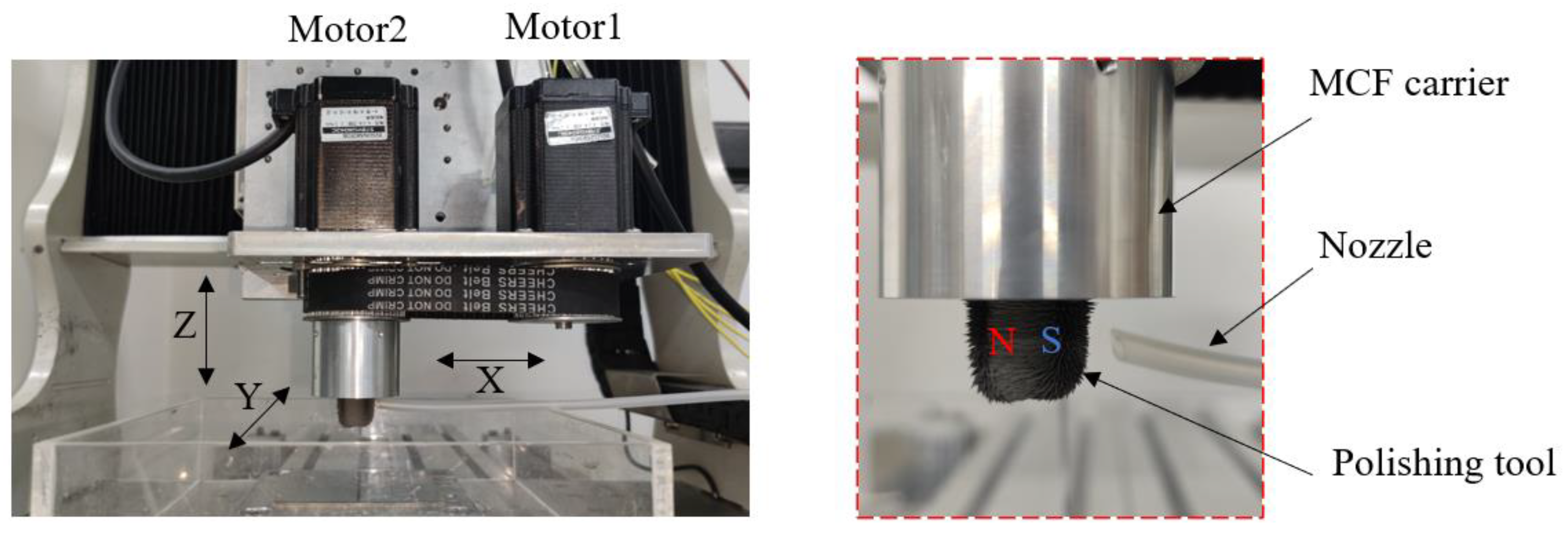
2.2. Experimental Setup

To realize the purpose in practice, the experimental setup was designed and customized. As shown in Figure 2, a cylinder-shaped permanent magnet (ND35,8-mm diameter, 20-mm thickness, 0.5 Tesla), drivers, and the MCF carrier were assembled and mounted onto the Z-direction axis of a self-made 3-direction milling machine (0.02 mm in repeated positioning accuracy). The MCF carrier could be rotated by motor 1 via a belt/pulley mechanism. The magnet was fixed to the lower tip of a rigid linker that was rigidly mounted to the shaft of motor 2. The workpiece was fixed onto the workbench. The three motion axes could move according to the given program to realize the polishing scanning tracks. To obtain a small MCF polishing tool with appropriate dimensions, the magnet dimensions were determined by the structure of the employed concave surfaces. As shown in the right portion of Figure 2, after an amount of magnetic compound fluid was injected into the outer surface of the MCF carrier, the polishing tool was formed immediately, and abundant ferric clusters were observed around the MCF carrier. The abrasive particle slurry with an alkaline solution was dropped from the nozzle to the polishing area for softening the workpiece surface by hydration reaction and remove the softened layer with abrasive particles during polishing.

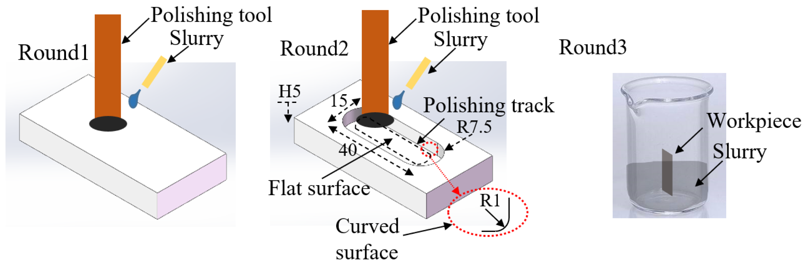
2.3. Experimental Conditions

The initial properties of the employed zirconia ceramics are a density of 6.0 g/cm3, a Young’s modulus of 205 GPa, and a compressive strength of 2200 MPa. After each experiment, the workpiece was submerged in dehydrated alcohol and cleaned by an ultrasonic cleaner for 30 min, and then the remaining liquid was blown away from the workpiece surface by high-pressure gas. The cross-section of the polished area was measured to obtain the maximum material removal depth d, and the maximum material removal depth was divided by the polishing time to obtain the material removal rate, namely, the material removal rate was calculated by MRR = d/t, where d is the distance of the deepest point to the initial surface curve based on the material removal curve and t is the polishing time. Additionally, a white light interferometer (CCI HD, English Taylor Hobson, 0.01 nm in resolution ratio) was used to scan the surface topography of the workpiece to measure the surface roughness at the deepest point and extract the surface profile based on the ISO 25178 standard.
The fundamental spot experiments were conducted on a flat workpiece with an initial surface roughness Ra of 20 nm around. Then, a workpiece with a concave surface (composed of a flat surface and a quarter arc with a radius of 2 mm) was employed for the polishing experiments. Two areas were selected on the flat surface and the curved surface for measuring the polishing results. Finally, the soaking experiments with different slurries for investigating the effect of a pH regulator on the hardness reduction were conducted. The experimental workflow is shown in Figure 3. All the workpieces were provided by CCCC Second Harbor Engineering Co., Ltd., Wuhan, China.
This experiment mainly studies the effects of the revolution speed of the MCF carrier (nc), working gap (h), and carbon iron particle size on the surface roughness and material removal rate. The polishing time was 30 min. The revolution speed of the magnet was 500 rpm. The drop rate of abrasive particle slurry (10 wt.% Al2O3, pH 10, pH regulator: NaOH) was 0.1 g/second. The composition of the magnetic compound fluid was carbon iron particles 65 wt.%, Fe3O4 (20 nm in diameter) 2 wt.%, α-cellulose (7 nm in length) 3 wt.%, and deionized water 30 wt.%. The scan velocity was 0.5 mm/sec, maintaining the distance of the polishing tool fringe to the side face of the concave surface, the same with working gap h during polishing. All the experimental materials were provided by the Sinopharm Group with AR level. The factors and levels of the orthogonal experiment are shown in Table 1. The signal-to-noise ratio (S/N) was used to analyze the results. A smaller surface roughness and a greater material removal rate were preferred in this experiment. Therefore, to analyze the polishing characteristics, the S/N calculation formula Equation (1) for the small features and the great features, Equations (1) and (2) are used.
S / N = 10 Log 10 ( 1 n i = 1 n 1 y i 2 )
S / N = 10 Log 10 ( 1 n i = 1 n y i 2 )  
where n is the number of the repeated experimental rounds, i is the sample number in the repeated experiments, and yi is the experimental results. In this experiment, n is 3 and yi is the obtained surface roughness or material removal rate.

3. Results and Discussion

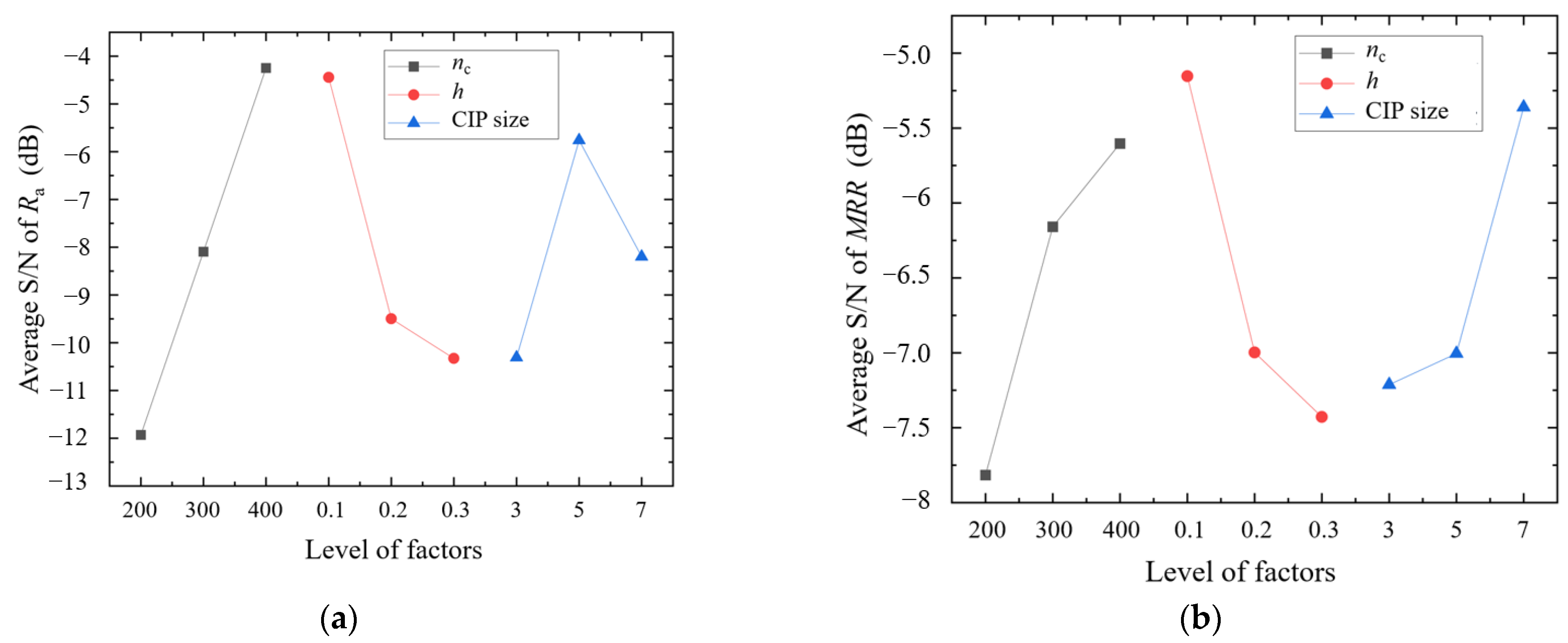
3.1. Effect of Polishing Parameters on Ra and MRR

An L9(33) orthogonal experiment was designed by the Taguchi method to study the effect of each process parameter on the evaluation index. The experimental results and S/N values are listed in Table 2. The average S/N was obtained by Equation (3) under each single factor.
average   S / N = S / N N o . i 3
The effect of the MCF carrier revolution speed (nc), working gap (h), and carbon iron particle size on the surface roughness Ra is shown in Figure 4. Regarding the surface roughness, with the increase in the revolution speed of the MCF carrier, the average S/N of the surface roughness Ra continually increased. The largest average S/N was obtained when the speed reached 400 rpm. When the revolution speed increased, the tangential movement between the abrasive particles and workpiece material was improved. Therefore, more material was sheared off from the workpiece surface by the abrasive particles per round, which can also be verified by the relationship between the average S/N of the MRR and the revolution speed nc. As the working gap h increased, the average S/N of Ra and MRR decreased gradually. As the working gap increased, the distance of the workpiece surface to the magnet was increased, which led to a decrease in the magnetic force acting on the abrasive particles. Hence, the polishing force decreased due to the weakness in the magnetic field strength. With the increase in CIP size, the average S/N of Ra first increased and then decreased. When the CIP size reached 5 μm, the average S/N of Ra was the largest. However, with the increase in CIP size, the average S/N of the MRR increased from −7.2 to −5.4. When the CIP size increased, the magnetization intensity of the polishing tool was enhanced, which resulted in an enhancement in the polishing force, including the normal force and tangential force. However, an excessively large polishing force is beneficial to material removal but is not friendly to the surface quality because a deeper normal cutting depth of the abrasive particles can be induced easily by a larger polishing force. Although abundant material was removed by a larger polishing force, it resulted in more microcracks and damage on the surface, which then makes the surface rough. In addition, an appropriate CIP size is apt to grip the abrasive particles, which is essential to maintain the optimal cutting performance of the abrasive particles. According to the S/N analysis through the Taguchi method, the optimal processing parameters of the revolution speed of the MCF carrier nc, working gap h, and CIP size were studied, and the optimal process parameters for the surface roughness and material removal rate are A3B1C2 (the revolution speed of MCF carrier nc is 400 rpm, the working gap h is 0.1 mm, and the CIP size D is 5 μm) and A3B1C3 (the revolution speed of MCF carrier nc is 400 rpm, the working gap h is 0.1 mm, and the CIP size D is 7 μm).
The average value of the experimental data of k groups is
y ¯ = 1 k i = 1 k y S N , i
where ySN,i is the experimental result (surface roughness or material removal rate) of number k in Table 2. In this experiment, k = 9. Calculate the average value of the experimental result under each experimental factor and level by Equation (5), as shown in Table 3.
y p , q ¯ = ( y p , q , 1 + y p , q , 2 + y p , q , 3 ) / 3
The influence weight of each factor can be obtained by Equation (6).
P x = 1 u j = 1 u ( y p , q ¯ y ¯ ) 2
where Px is the average value of the experimental result under factor x, j is the number of levels, and u is the quantity of factors. In this experiment, u = 3.
A variance analysis was performed on the results of the orthogonal test to evaluate the effect of the processing parameters on the surface roughness and material removal rate. The final weight map is shown in Figure 5. It can be seen from the figure that as the influence trend of the process parameters on roughness and material removal rate is different, the weight proportion is different. The revolution speed of the MCF carrier has the most significant effect on surface roughness, accounting for 54%, followed by the working gap, accounting for 31%. The CIP size only accounts for 15%. Regarding the material removal rate, the working gap has the greatest contribution to the material removal rate, accounting for 40%, followed by the revolution speed of the MCF carrier, accounting for 32%. The CIP size accounts for 28%.

3.2. Polishing Characteristics

With polishing condition A3B1C2, the variation in surface roughness Ra with an increasing spot polishing time on the flat workpiece is shown in Figure 6. As the polishing time increased, the surface roughness decreased sharply in the first 20 min, and then the decrease rate decreased and tended to be stable in the last 10 min of polishing. The final surface roughness Ra reached 0.8 nm. The 3D polished area was measured under A3B1C3 conditions. As shown in Figure 7a, a circular polished area was observed. Because both the relative velocity and the distribution of the magnetic field strength increase from the middle to the fringe, according to Preston theory MRR = KPv (K is the coefficient, P is the polishing press, and v is the relative velocity of the abrasive particle to the workpiece), the deepest point at the material removal curve was close to the fringe of the material removal curve, as shown in Figure 7b. Meanwhile, the slurry was dropped at the fringe of the polishing tool, and the abrasive particles were distributed unevenly within the polishing tool when spot polishing. Because of the centrifugal force that acted on the abrasive particles and the grip of the cluster, more abrasive particles aggregated around the fringe of the polishing tool, which also led to higher material removal at the fringe than at the inner side. When the polishing radius extends beyond almost 6 mm, which is far away from the magnetic field, the material cannot be removed efficiently because of the rapid reduction in the magnetic force acting on the ferric particles.
Then, the concave workpiece was used for polishing. After polishing for 30 min under the optimal processing parameters A3B1C2, the typical variation of the surface topographies is displayed in Figure 8 before and after polishing. The cracks and small pits were found in the initial surface, and the surface roughness was approximately Ra 20 nm (Figure 8a,c, left portion). As the polishing time increased, these defects were gradually eliminated. Within 60 min of polishing, the final surface was smooth without any obvious defects (Figure 8b,c, left portion). The surface roughness Ra reached 1 nm at the flat surface and 1.2 nm at the curved surface after 60 min of scanning polishing.

3.3. Material Removal Mechanism

To investigate the material removal mechanism of this method, a soaking experiment was carried out by soaking the workpiece in different polishing slurries for 30 min. Three kinds of polishing slurries were employed. The basic slurry was 40 wt.% CIP with a 5 μm diameter, 45 wt.% water-based magnetic fluid with 5 wt.% Fe3O4, 12 wt.% Al2O3 with a 1 μm diameter, 3 wt.% α-cellulose, and pH 7. Then, the pH was adjusted to 10 with different regulators (NaHCO3, NaOH). The Vickers hardness of the workpiece surface was measured by a Vickers hardness tester (ZHV30, German ZwickRoell, 0.1 μm resolution ratio) before and after the experiments. Each hardness measurement was repeated 10 times, and the count average value was used as the final Vickers hardness. It was found that hardness was changed after soaking at different pH values. The initial hardness was approximately 1320 HV, and the hardness was changed to 1248 HV at pH 7, 1135 HV at pH 10 (NaHCO3), and 1008 HV at pH 10 (NaOH). Obviously, it was summarized that the pH value and pH regulator affect the workpiece hardness. The softened layer was formed on the workpiece surface due to the chemical action. The variation in hardness with the soaking time is shown in Figure 9. It can be seen that the hardness of the workpiece surface was reduced as the soaking time increased. However, a slight difference with a reduction rate of 5.4% was found at pH 7, and the difference was increased at pH 10. Moreover, the highest reduction rate was found when NaOH was used as a pH regulator.
The chemical corrosion of zirconia ceramics in an alkaline solution is induced by the hydration reaction [23]. In the alkaline environment, the hydration reaction on the zirconia ceramic workpiece surface prompts the Zr–O–Zr bond to form Zr–O–H with water molecules [24]. The surface hardness was reduced because the chemical output of the hydration reaction was soft and loose in structure. Moreover, there are no obvious changes in mass. The chemical output can be easily removed from the workpiece surface by abrasive particles. Therefore, the polishing slurry can enhance the material removal rate and polishing efficiency by combining chemical and mechanical functions. Moreover, when NaOH was used as a pH regulator, the hydration reaction was highly improved due to the strong alkaline characteristic of NaOH. Hence, the chemical reaction on the workpiece surface was much more drastic than the pH regulators with less alkaline characteristics. In summary, the material removal was attributed to the chemical and mechanical function, which has a huge improvement in polishing efficiency compared to individual chemical corrosion or mechanical function. However, the quantitative study on polishing efficiency between a conventional small polishing tool and the new method will be provided in detail in the future. Furthermore, as a kind of strong base, the NaOH solution was harmful to people’s health and the mechanical structure of the polishing machine. A friendly solution should be employed instead of the NaOH solution. A study will be conducted in the following work to assess a better alternative.

4. Conclusions

As prominent engineering materials, structural products made of zirconia ceramics are widely used in computers, consumer electronics, and the fifth-generation communication industry. However, zirconia ceramics are a typical hard-to-cut material, and it is difficult to improve the polishing efficiency, especially in zirconia ceramics with concave surfaces. To overcome this problem, a small MCF polishing tool enhanced by a hydration reaction was utilized.
A higher revolution speed of the MCF carrier and a smaller working gap were apt to obtain better surface roughness and a higher material removal rate. However, a CIP diameter of 5 μm resulted in the best surface roughness, and a CIP diameter of 7 μm resulted in the highest removal rate. The optimal polishing parameters were A3B1C2 for better surface roughness and A3B1C3 for a higher material removal rate. The impact degrees on surface roughness and material removal rate were a revolution speed of MCF carrier > working gap > CIP size and working gap > revolution speed of MCF carrier > CIP size, respectively.
The basic material removal curve was a circular area in spot polishing on a flat workpiece. As the concave workpiece was finally polished under optimal polishing parameters, the best surface roughness Ra reached 1.1 nm on the flat surface and 1.3 nm on the curved surface after 60 min of polishing.
The hardness of the workpiece surface was reduced after soaking in different slurries. The stronger the alkaline characteristic of the pH regulator is, the greater the reduction in hardness. The results show that the proposed method can combine the chemical and mechanical functions for removing surface material, which can first soften the surface material first, and then remove the material by abrasive particles more easily than that without chemical action.
For further improvement in the application of the proposed method, a quantitative study on the polishing efficiency between a small polishing tool with and without a hydration reaction should be conducted in the future, the effect of the pH value on polishing results should be investigated, and a friendly solution must be provided instead of a NaOH solution.

Author Contributions

Conceptualization, X.L.; data curation, J.H. and Y.L.; investigation, M.F.; methodology, Q.C.; supervision, M.F.; validation, X.L.; writing—original draft preparation, M.F.; writing—review and editing, M.F.; visualization, X.L.; project administration, J.H.; funding acquisition, M.F. All authors have read and agreed to the published version of the manuscript.

Funding

This research was supported by the Natural Science Foundation of Zhejiang Province (CN) (grant No. LQ22E050008); the Major science and technology innovation project of Wenzhou (CN) (grant No. ZG2022029); and the Natural Science Foundation of Wenzhou City (CN) (grant No. G20210001).

Institutional Review Board Statement

Not applicable.

Informed Consent Statement

Not applicable.

Data Availability Statement

The data presented in this study are available on request from the corresponding author.

Conflicts of Interest

The authors declare no conflict of interest.

References

  1. Ammarullah, M.I.; Santoso, G.; Sugiharto, S.; Supriyono, T.; Wibowo, D.B.; Kurdi, O.; Tauviqirrahman, M.; Jamari, J. Minimizing Risk of Failure from Ceramic-on-Ceramic Total Hip Prosthesis by Selecting Ceramic Materials Based on Tresca Stress. Sustainability 2022, 14, 13413. [Google Scholar] [CrossRef]
  2. Jamari, J.; Ammarullah, M.I.; Saad, A.P.M.; Syahrom, A.; Uddin, M.; van der Heide, E.; Basri, H. The Effect of Bottom Profile Dimples on the Femoral Head on Wear in Metal-on-Metal Total Hip Arthroplasty. J. Funct. Biomater. 2021, 12, 38. [Google Scholar] [CrossRef] [PubMed]
  3. Zhelun, M.; Zhao, W.; Xuezhi, W.; Yu, T. Effects of Laser-Assisted Grinding on Surface Integrity of Zirconia Ceramic. Ceram. Int. 2020, 46, 921–929. [Google Scholar]
  4. Jang, J.-G.; Kang, J.-H.; Joe, K.-B.; Sakthiabirami, K.; Jang, K.-J.; Jun, M.-J.; Oh, G.-J.; Park, C.; Park, S.-W. Evaluation of Physical Properties of Zirconia Suspension with Added Silane Coupling Agent for Additive Manufacturing Processes. Materials 2022, 15, 1337. [Google Scholar] [CrossRef] [PubMed]
  5. Lei, Y.; Feng, M.; Wu, K.; Chen, J.; Ji, J.; Yuan, J. Investigation on the Basic Characteristics of Semi-Fixed Abrasive Grains Polishing Technique for Polishing Sapphire (α-Al2O3). Materials 2022, 15, 3995. [Google Scholar] [CrossRef]
  6. Preis, V.; Grumser, K.; Schneider-Feyrer, S.; Behr, M.; Rosentritt, M. The Effectiveness of Polishing Kits: Influence on Surface Roughness of Zirconia. Int. J. Prosthodont. 2018, 28, 149–151. [Google Scholar] [CrossRef] [Green Version]
  7. Min, L.; Minhui, L.; Oltmann, R.; Bernhard, K.; Cheng, T. Origin of Material Removal Mechanism in Shear Thickening-Chemical Polishing. Int. J. Mach. Tools Manuf. 2021, 170, 103800. [Google Scholar]
  8. Kheur, M.; Lakha, T.; Shaikh, S.; Kheur, S.; Qamri, B.; Zhen, L.W.; Al-Haj Husain, N.; Özcan, M. A Comparative Study on Simulated Chairside Grinding and Polishing of Monolithic Zirconia. Material 2022, 15, 2202. [Google Scholar] [CrossRef]
  9. Youliang, W.; Xiaofeng, S.; Xiujuan, C. Polishing Performance of Magnetic Composite Fluid Based on Double Magnetic Fields. Surf. Technol. 2022, 51, 360–372. [Google Scholar]
  10. Franco-Tabares, S.; Wardecki, D.; Nakamura, K.; Ardalani, S.; Hjalmarsson, L.; Stenport, V.F.; Johansson, C.B. Effect of Airborne-Particle Abrasion and Polishing on Novel Translucent Zirconias: Surface Morphology, Phase Transformation and Insights into Bonding. J. Prosthodont. Res. 2021, 65, 97–105. [Google Scholar] [CrossRef]
  11. Cheng, C.; Xiaohua, Z. Effects of Different Polishing Systems on Surface Roughness and Crystal Structure of Zirconia. Appl. Bionics Biomech. 2022, 7, 99–105. [Google Scholar]
  12. Hmaidouch, R.; Müller, W.D.; Lauer, H.C.; Weigl, P. Surface Roughness of Zirconia for Full-Contour Crowns After Clinically Simulated Grinding and Polishing. Int. J. Oral Sci. 2018, 6, 241–246. [Google Scholar] [CrossRef] [PubMed] [Green Version]
  13. Guo, J.; Feng, W.; Jong, H.J.H.; Suzuki, H.; Kang, R. Finishing of Rectangular Microfeatures by Localized Vibration-Assisted Magnetic Abrasive Polishing Method. J. Manuf. Process. 2020, 49, 204–213. [Google Scholar] [CrossRef]
  14. Shafrir, S.N.; Romanofsky, H.J.; Skarlinski, M.; Wang, M.; Miao, C.; Salzman, S.; Chartier, T.; Joni, M.; Lambropoulos, J.C.; Shen, R.; et al. Zirconia-Coated Carbonyl-Iron-Particle-Based Magnetorheological Fluid for Polishing Optical Glasses and Ceramics. Appl. Opt. 2015, 35, 97–122. [Google Scholar] [CrossRef]
  15. Kum, C.W.; Sato, T.; Guo, J.; Liu, K.; Butler, D. A Novel Media Properties-Based Material Removal Rate Model for Magnetic Field-Assisted Finishing. Int. J. Mech. Sci. 2018, 141, 189–197. [Google Scholar] [CrossRef] [Green Version]
  16. Wang, Y.; Wu, Y.; Nomura, M. Feasibility Study on Surface Finishing of Miniature V-Grooves with Magnetic Compound Fluid Slurry. Precis. Eng. 2016, 45, 67–78. [Google Scholar] [CrossRef]
  17. Luo, H.; Guo, M.; Yin, S.; Chen, F.; Huang, S.; Lu, A.; Guo, Y. An Atomic-Scale and High Efficiency Finishing Method of Zirconia Ceramics by Using Magnetorheological Finishing. Appl. Surf. Sci. 2018, 7, 69–78. [Google Scholar] [CrossRef]
  18. Wang, L.; Wu, Y. Feasibility Study on the Precision Polishing of Zirconia Ceramics with Magnetic Compound Fluid (MCF) Slurry Under the Assistance of Dielectrophoresis Effect. Sci. Adv. Mater. 2021, 5, 55–70. [Google Scholar] [CrossRef]
  19. Yang, P.; Zhou, S.; Lei, J. Preparation of Ordered Mesoporous Nanocrystalline Ceria and Ceria-zirconia for Soot Oxidation. J. Wuhan Univ. Techonol.-Mater. Sci. Ed. 2018, 31, 113–117. [Google Scholar] [CrossRef]
  20. Feng, M.; Xie, Y.; Chen, L.; Wu, Y. Investigation on Polishing Feasibility of the Concave Surface with Magnetic Compound Fluid (MCF) Slurry. Int. J. Autom. Technol. 2021, 15, 34–40. [Google Scholar]
  21. Jin, M.; Zhao, J.; Zheng, Y. Effects of Grinding and Polishing on Surface Characteristics of Monolithic Zirconia Fabricated by Different Manufacturing Processes: Wet Deposition and Dry Milling. J. Prosthodont. 2022, 8, 714–721. [Google Scholar] [CrossRef] [PubMed]
  22. Hu, J.; Guo, H.; Yang, F.; Feng, H.; Du, W.; Yang, Q. Luminescent Properties and X-Ray Imaging Result of Lu2O3:Eu Structured Scintillation Film on YSZ Single Crystal Substrate by LCVD Method. Ceram. Int. 2021, 9, 55–103. [Google Scholar] [CrossRef]
  23. Feng, M.; Wang, Y.; Wu, Y. Investigation on Polishing of Zirconia Ceramics Using Magnetic Compound Fluid: Relationship Between Material Removal and Surface Roughness. Int. J. Autom. Technol. 2021, 2, 17–23. [Google Scholar] [CrossRef]
  24. Han, J.; Malek, O.; Vleugels, J.; Braem, A.; Castagne, S. Ultrashort Pulsed Laser Ablation of Zirconia-Alumina Composites for Implant Applications. J. Mater. Process. Technol. 2022, 299, 117335. [Google Scholar] [CrossRef]
Figure 1. Schematic of the proposed polishing method.
Magnetochemistry 09 00074 g001
Figure 2. Experimental setup.
Magnetochemistry 09 00074 g002
Figure 3. Experimental workflow (unit: mm).
Magnetochemistry 09 00074 g003
Figure 4. Effects of the revolution speed of the MCF carrier nc, working gap h, and carbon iron particle CIP size on (a) Ra and (b) MRR.
Magnetochemistry 09 00074 g004
Figure 5. The proportional weight of the three factors on (a) the surface roughness and (b) the material removal rate.
Magnetochemistry 09 00074 g005
Figure 6. Variation in surface roughness Ra with polishing time.
Magnetochemistry 09 00074 g006
Figure 7. Three-dimensional profile of the polished area: (a) 3D profile and (b) profile along the radius.
Magnetochemistry 09 00074 g007
Figure 8. Variation in surface topographies: (a) initial, (b) 60 min polishing, and (c) actual topography of the workpiece before (left) and after (right) polishing.
Magnetochemistry 09 00074 g008
Figure 9. Variation in hardness with soaking time.
Magnetochemistry 09 00074 g009
Table 1. Factors and levels of the orthogonal experiment.
LevelFactor
nc (rpm)
A
h (mm)
B
D (μm)
C
12000.13
23000.25
34000.37
Table 2. Orthogonal experimental parameters and experimental results.
Experiment No.FactorResult
ABCAverage Roughness Ra (nm)S/NMaterial Removal Rate MRR (μm/min)S/N
12000.133.4−10.630.43−7.35
22000.253.93−11.900.37−8.56
32000.374.6−13.260.42−7.54
43000.151.13−1.090.55−5.25
53000.273.1−9.740.52−5.68
63000.334.7−13.440.42−7.54
74000.171.2−1.600.72−2.86
84000.232.2−6.850.46−6.75
94000.351.6−4.290.44−7.20
Table 3. Mean values at each level for each factor.
FactorValueRa (nm)MRR (μm/min)
nc2003.90.41
3002.90.49
4001.60.54
h0.11.90.57
0.23.10.45
0.33.60.43
D33.40.44
52.20.45
72.90.55
Disclaimer/Publisher’s Note: The statements, opinions and data contained in all publications are solely those of the individual author(s) and contributor(s) and not of MDPI and/or the editor(s). MDPI and/or the editor(s) disclaim responsibility for any injury to people or property resulting from any ideas, methods, instructions or products referred to in the content.

