Article

Effects of External Resistance, New Electrode Material, and Catholyte Type on the Energy Generation and Performance of Dual-Chamber Microbial Fuel Cells

by
Miguel Ángel López Zavala
* and
Iris Cassandra Cámara Gutiérrez
Tecnologico de Monterrey, School of Engineering and Science, Av. Eugenio Garza Sada Sur No. 2501, Col. Tecnológico, Monterrey 64700, NL, Mexico
*
Author to whom correspondence should be addressed.
Fermentation 2023, 9(4), 344; https://doi.org/10.3390/fermentation9040344
Submission received: 31 December 2022 / Revised: 11 March 2023 / Accepted: 21 March 2023 / Published: 29 March 2023

Abstract

:
In this study, the effects of an external resistance, new electrode material, and non-conventional catholyte on the energy generation and performance of a dual-chamber MFC were evaluated. Ten different resistances (15 Ω–220 kΩ), hydrophilically-treated graphene and graphite electrodes, and a 0.1 M HCl solution as a catholyte were assessed. The results showed that greater energy generation and power density were achieved at an external resistance of 2 kΩ and internal resistance between 2 and 5 kΩ on average; meanwhile, the greatest coulombic efficiency was obtained at the lowest external resistance evaluated (15 Ω). Therefore, it is recommended to operate the MFCs at the external resistance between 2 and 5 kΩ to ensure the maximum power generation of the dual chamber MFCs. Regarding the two electrode materials evaluated as an anode and cathode, hydrophilically-treated graphene was found to be a much better material to enhance the energy production and performance of the MFC system; therefore, its use is suggested in experimental and practical applications. On the other hand, the use of HCl as a catholyte enhanced the performance of MFC (constant and steady potential and greater coulombic efficiency) in most cases.

Graphical Abstract

1. Introduction

In recent years, the international scientific community’s interest in microbial fuel cells has increased due to their potential applications and the great advantages they offer for simultaneous bioenergy production and wastewater treatment [1]. Important studies have been carried out to improve microbial fuel cells, focusing on cathode and anode materials [1,2,3,4,5,6,7,8,9,10,11,12,13,14,15,16,17,18,19], the proton exchange membrane [2,3,9,20,21,22,23,24], the configuration of MFCs [5,6,25,26,27,28,29,30,31,32,33,34], degradation of different types of substrates [7,12,27,28,29,33], bioenergy production [3,5,26,27,28,29,33,34,35,36,37], and MFC modelling [38]. However, external resistance is an issue that has not received enough attention despite its importance. Correct external resistance can improve the power output of MFC [39]. The flux of electrons from the anode to the cathode is controlled by external resistance, which has an important effect on the biomass communities and MFC performance [40]. Studies have demonstrated that a reduction in the external resistance of MFC enhances the current and power generation [41]. Furthermore, the application of different external resistances to the MFCs can alter biomass diversity and metabolism [41,42]. Under low external resistances, biofilms reduce the internal resistance, while high external resistances increase ohmic losses and decrease MFC performance [43]. It is well known that MFC power generation is optimized when the external and internal resistances of the cell are equal [40,44]. The MFCs are commonly operated under constant external resistance; nevertheless, the internal resistance varies significantly with time due to changes in biofilm growth, biomass decay, and operating conditions, resulting in remarkable differences between the internal and external resistances that cause a decrease in MFC energy generation. In practice, these differences can be solved by connecting a variable external resistance controller to the MFC. However, external resistance can be difficult to control manually because the internal resistance can change frequently, while external resistance variation can be carried out weekly or daily, thus causing significant ohmic losses [40,44].
As seen, most studies agree that to optimize the performance of MFCs, low external resistances are desirable; however, setting an optimum external resistance, or at least a range of external resistances, for most MFCs is challenging as it depends on several factors such as MFC configuration, the type of substrate, operating conditions, etc. Therefore, further research in this area is needed. Thus, in this study, an optimum external resistance was selected based on the overall performance of the MFC, resulting in a practical and simple method to ensure the best performance of the MFC. Furthermore, a new carbon-based electrode material (hydrophilically-treated graphene) was evaluated, resulting in a potential material to enhance the energy production and performance of the MFC system. Additionally, the use of a nonconventional catholyte such as a HCl solution improved, in most cases, the MFC performance (constant and steady potential and greater coulombic efficiency). Therefore, this strategy can be implemented in other studies when practical applications of MFCs are planned.

2. Materials and Methods

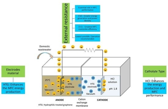
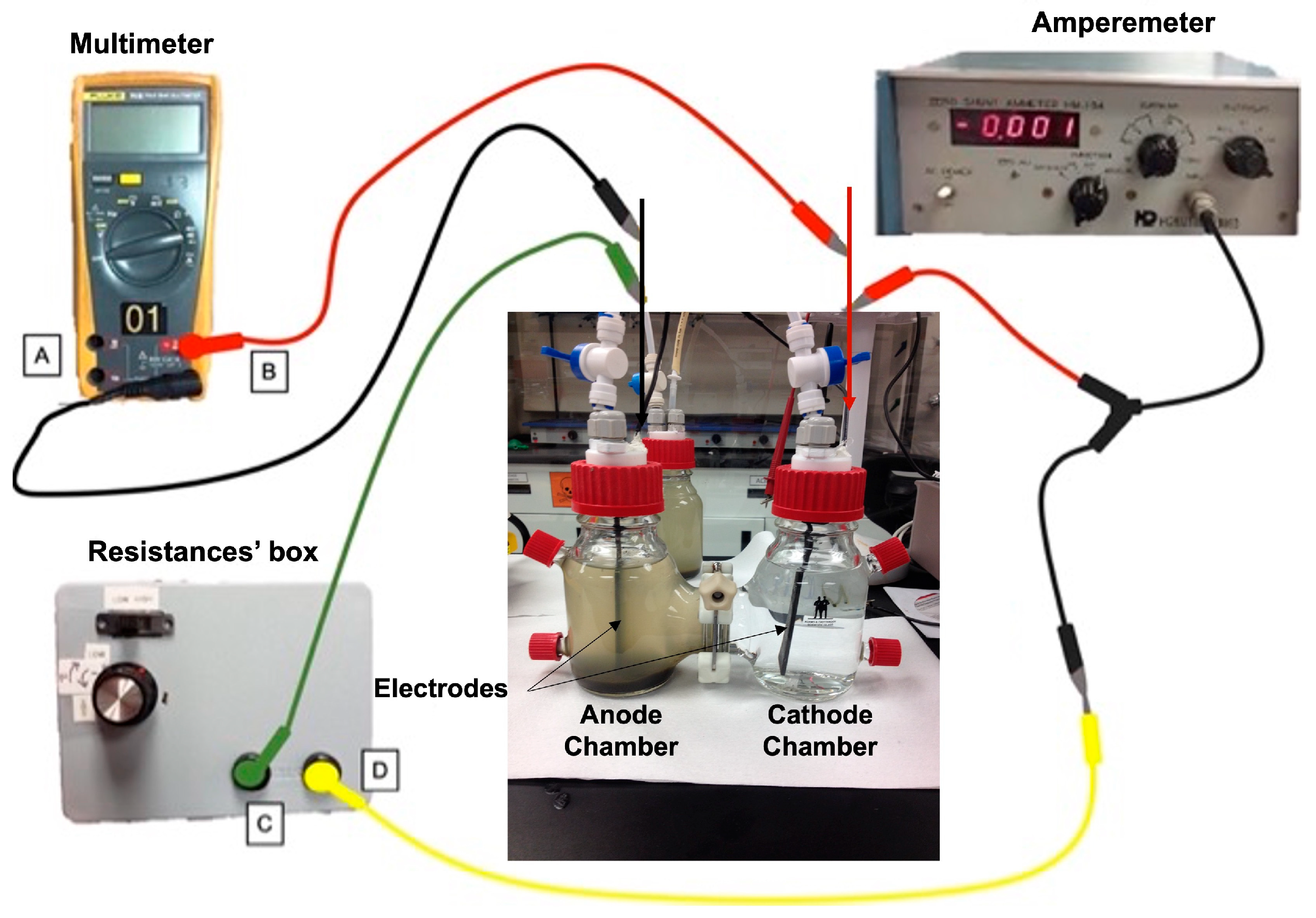
2.1. Experimental Setup
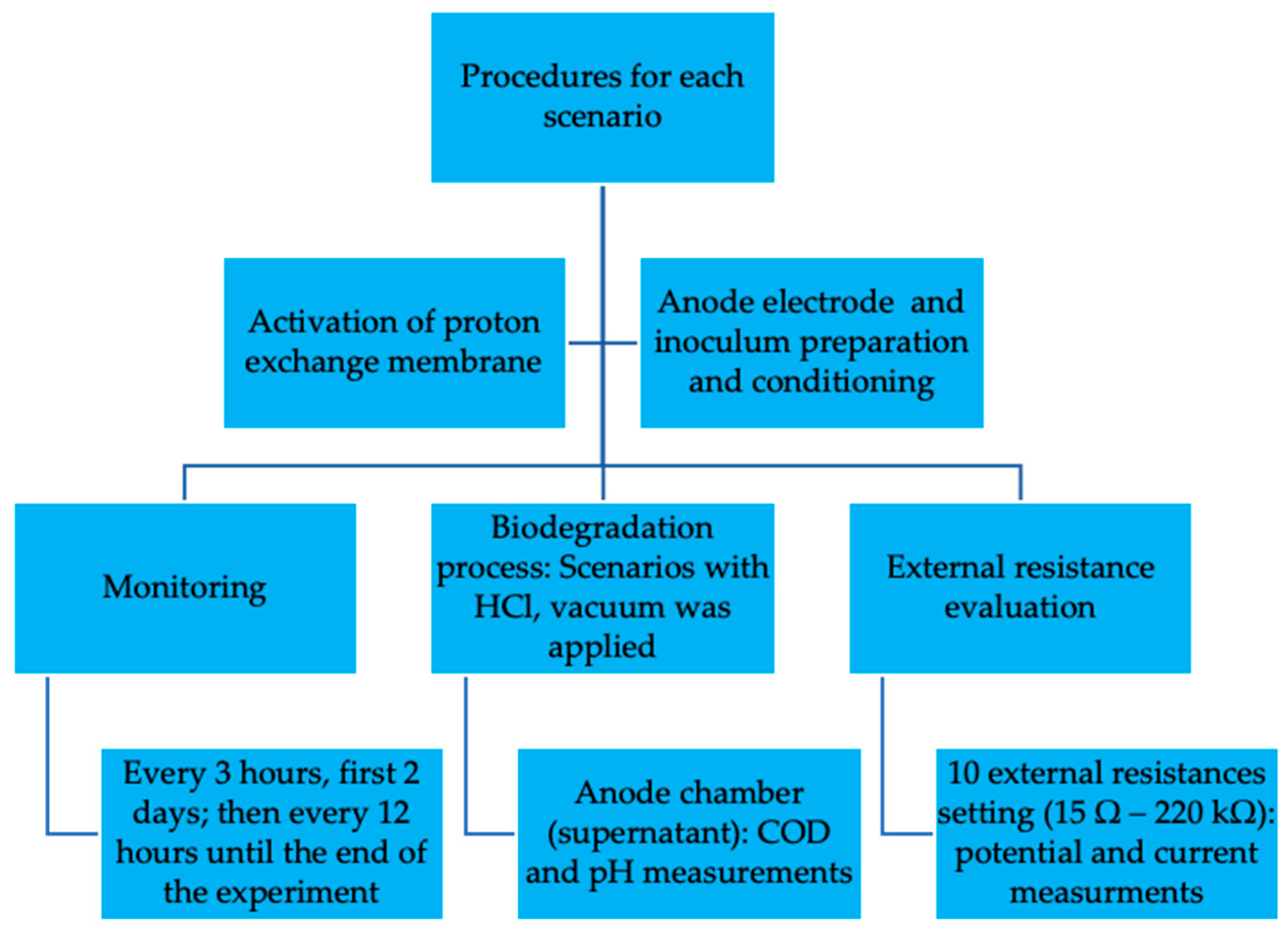
A dual-chamber MFC (Adams & Chittenden Scientific Glass, Berkeley, CA, USA) was used in this research. A DupontTM Nafion® 117 proton exchange membrane (PEM, Chemours/Nafion, Wilmington, USA) was set as a separator. Graphite and hydrophilically-treated graphene (Hitachi Chemical, Tokyo, Japan) electrodes (8.0 cm × 2.5 cm × 0.2 cm) connected to a resistance box were integrated into the external circuit. The resistances’ box allowed setting 10 different resistances between 15 Ω and 220 kΩ. The MFC potential and current were measured by using a multimeter and amperemeter (Hokuto-Denko, Tokyo, Japan), respectively. Distilled water and a 0.1 M HCl solution (pH 1.8) as a catholyte were used in the cathode chamber. Vacuum (77.3 kPa) was set in both chambers when a 0.1 M HCl solution was used as a catholyte. Ports in both chambers were used for sampling the mixed liquor and the electrolyte. The process was conducted in duplicate on two experimental devices set up in parallel. Figure 1 shows the lab-scale MFC with the electrical connections.

2.2. Procedures

2.2.1. Preparations for the Experiments

Before starting the experiments, some preparations were made to ensure the correct performance of the experimental device. Activation of the proton exchange membrane, inoculum preparation, and conditioning of the anode electrode were carried out before starting any tests. Nafion® 117 membrane was activated based on the protocol reported by Hasani-Sadrabadi et al. [21] to ensure the greatest proton conductivity through the active sites of the membrane. Anode biomass and anode electrode were prepared and conditioned, respectively, following the procedure described by López Zavala et al. [33]. For that purpose, bioreactor mixed liquor and domestic wastewater were taken from a municipal wastewater treatment plant located in the city of Monterrey, Mexico.

2.2.2. Biodegradation of Domestic Wastewater
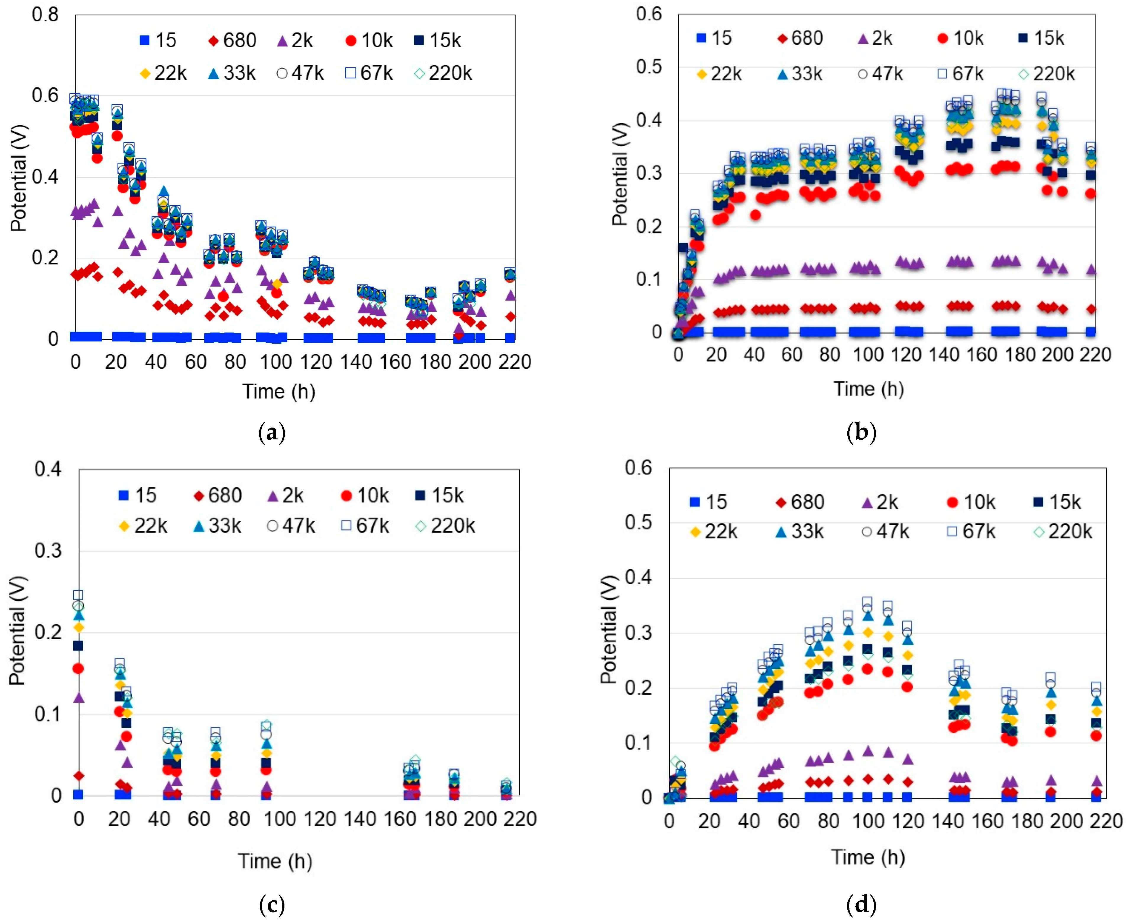
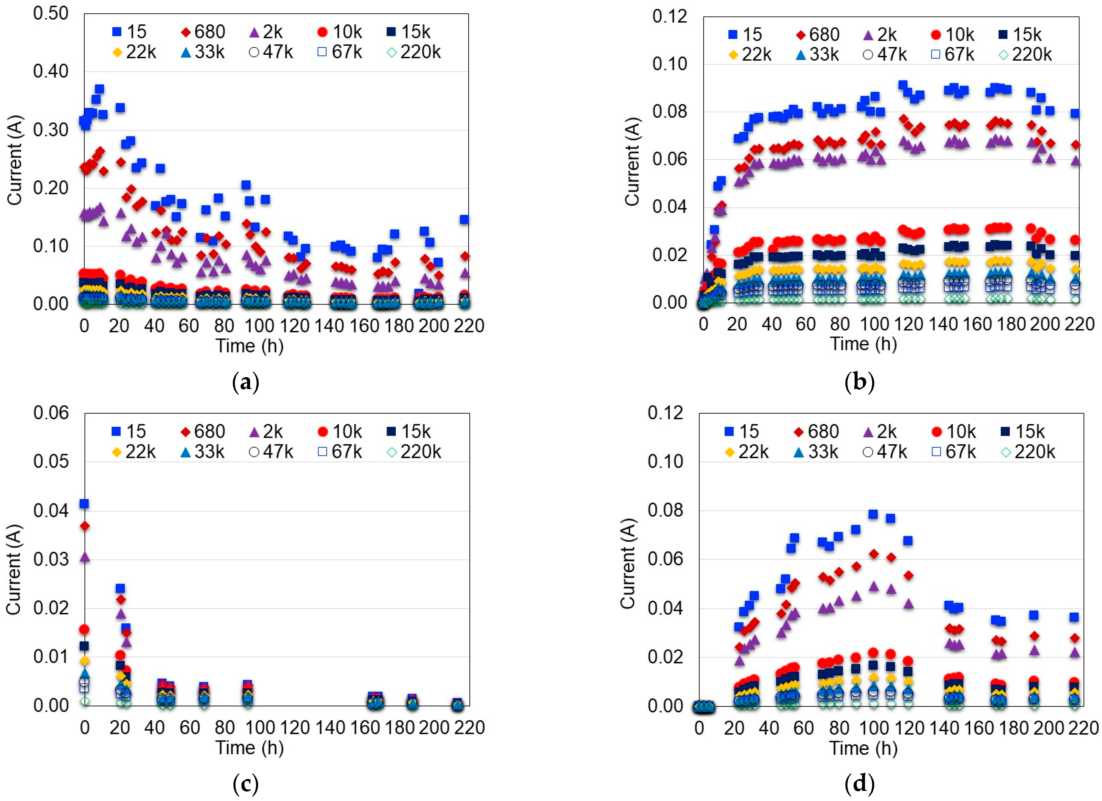
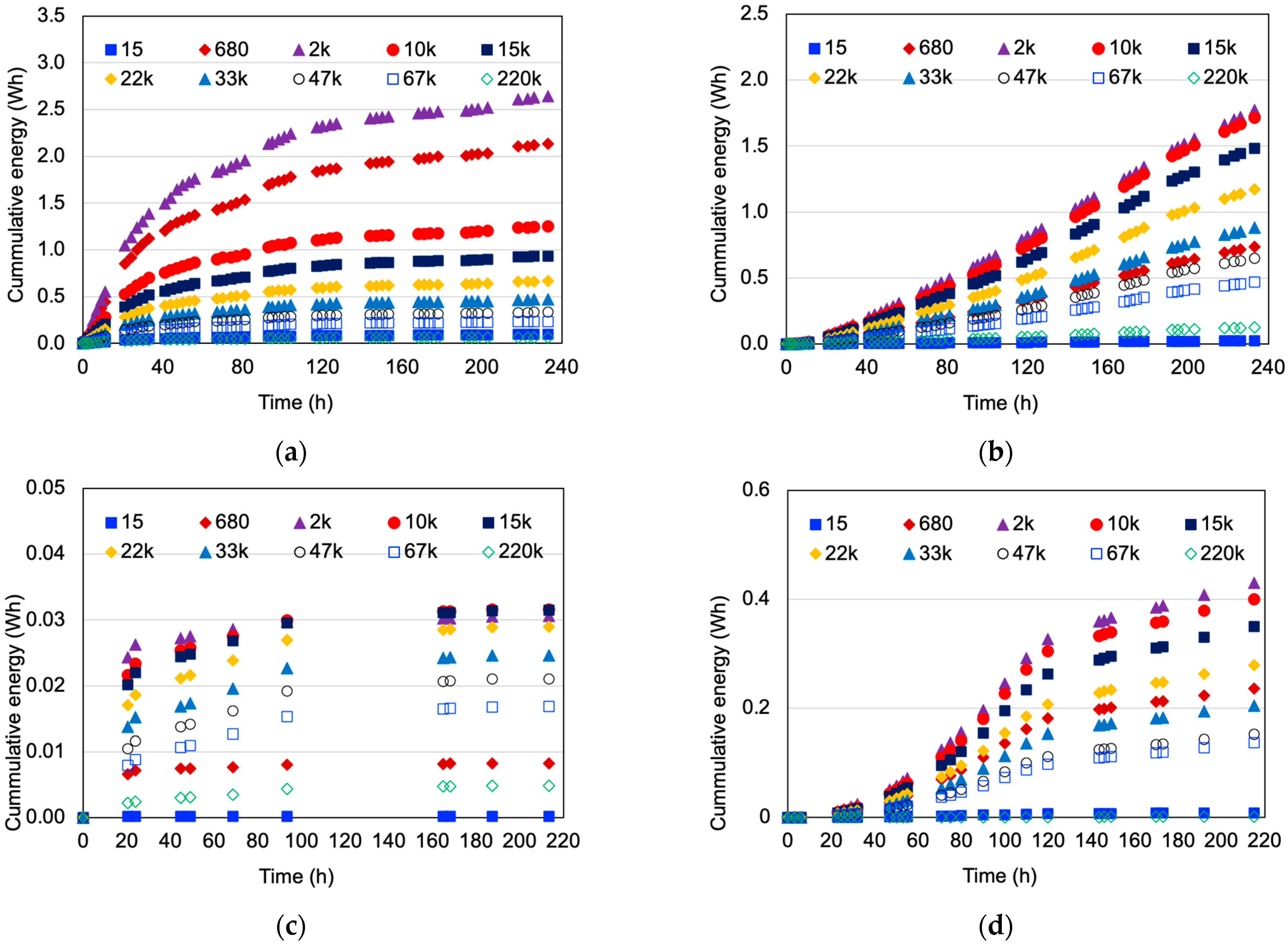
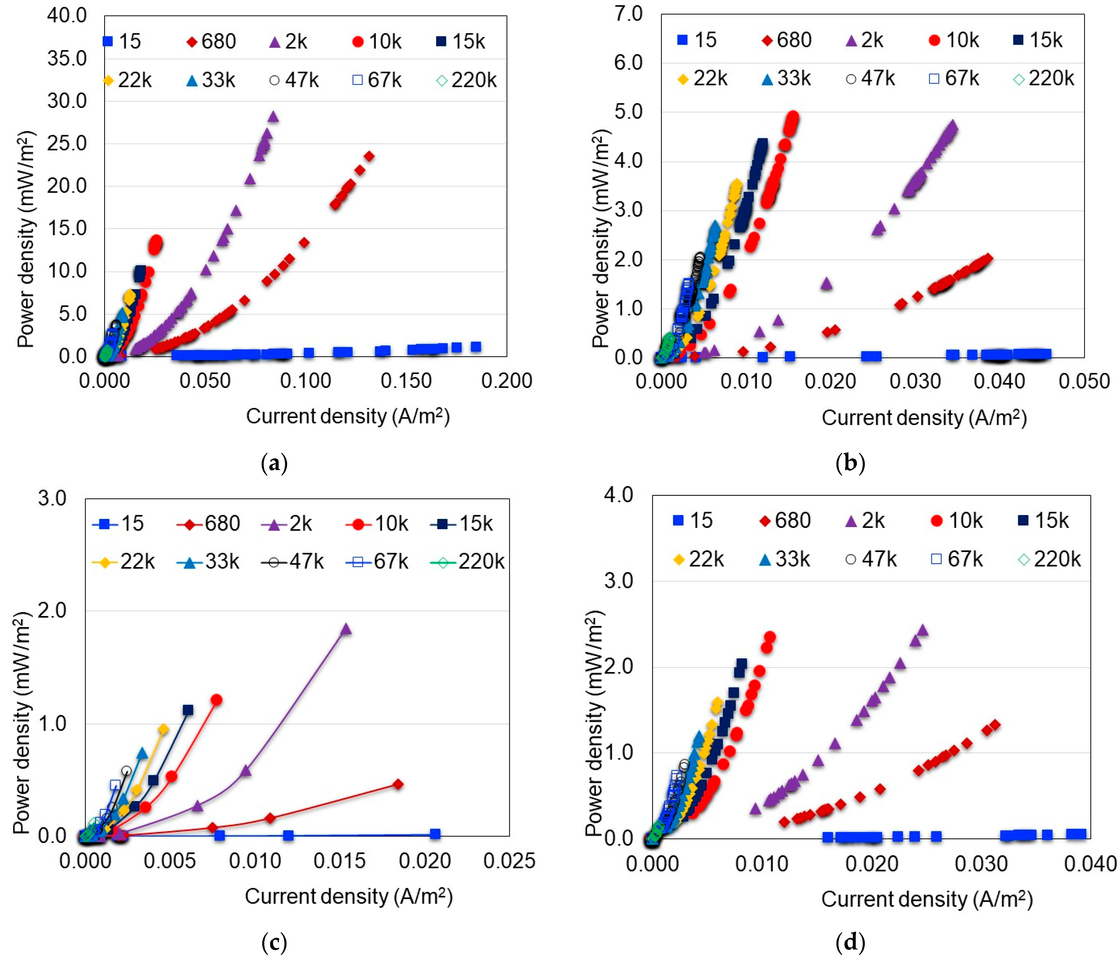
Biodegradation of domestic wastewater in the MFCs was conducted according to four different scenarios:
(a)
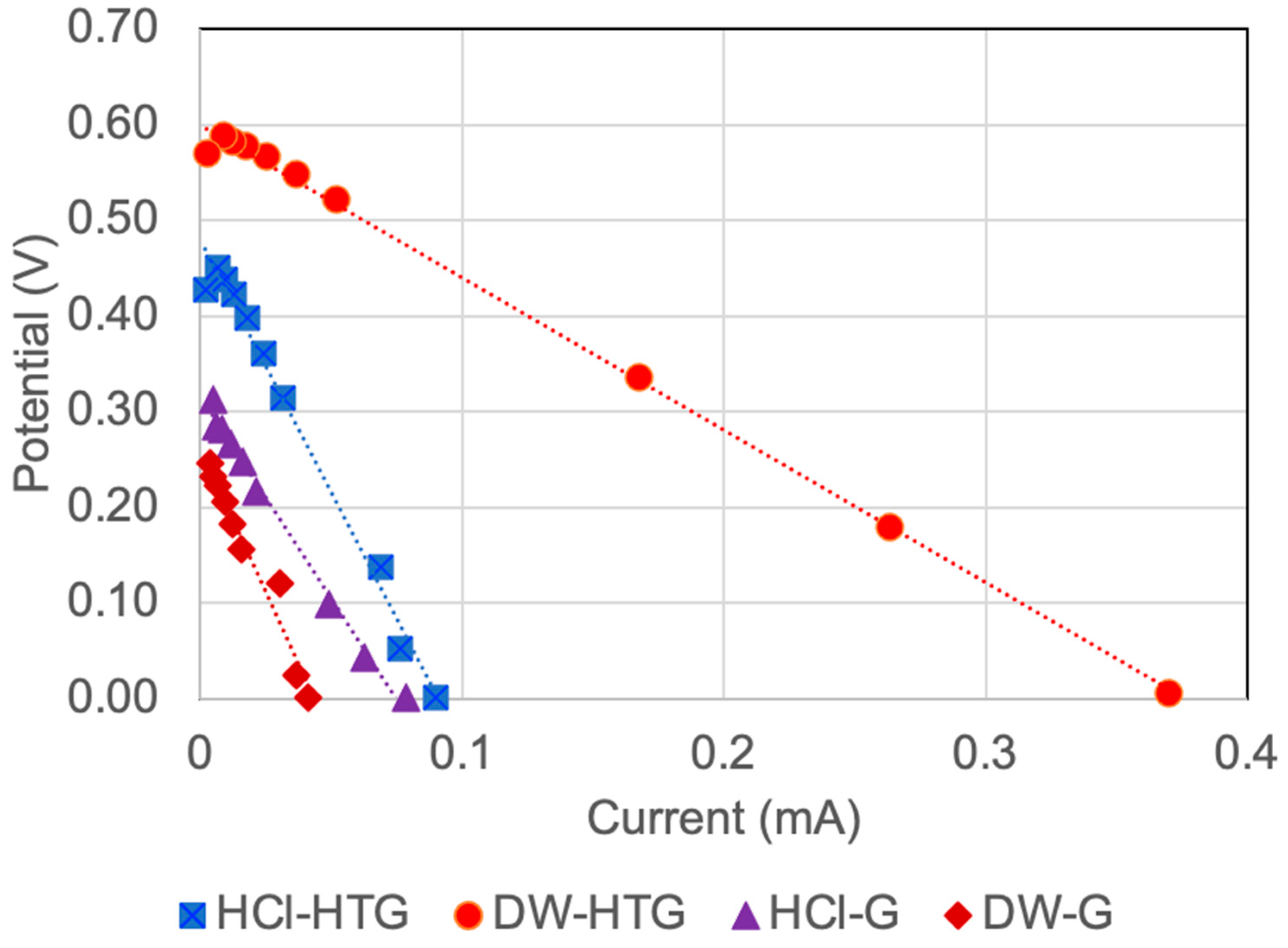
Scenario 1 (HCl-G): cathode electrolyte: hydrochloric acid; anode and cathode electrode material: graphite.
(b)
Scenario 2 (HCl-HTG): cathode electrolyte: hydrochloric acid; anode and cathode electrode material: hydrophilically-treated graphene.
(c)
Scenario 3 (DW-G): cathode electrolyte: distilled water; anode and cathode electrode material: graphite.
(d)
Scenario 4 (DW-HTG): cathode electrolyte: distilled water; anode and cathode electrode material: hydrophilically-treated graphene.
For the experiments, in the anode chamber, 35 mL of conditioned inoculum(biomass) was mixed with 265 mL of domestic wastewater (Chemical oxygen demand, COD: 533.4 mg/L; pH: 7.8). The cathode chamber in scenarios 1 and 2 was filled with 300 mL of 0.1 M HCl solution; meanwhile, for scenarios 3 and 4, the cathode chamber was filled with 300 mL of distilled water. All experiments were conducted in duplicate at room temperature 21 + 1 °C. In scenarios 1 and 2, air and dissolved oxygen were extracted from both chambers of the MFC by applying a vacuum (77.3 kPa).
Experiments were executed and the degradation process was monitored as follows: 2.5 mL supernatant samples were taken from the anode chamber every 3 h for the first 2 days and then every 12 h until the end of the experiments. Sampling was carried out through the side ports of the chambers by using a 5 mL plastic syringe (BD Plastik). Sampling was coupled with the electrical measurements. COD and pH of the samples were measured based on the Standard Methods for the Examination of Water and Wastewater [45]. The effect of the external resistance on the performance of the MFCs was evaluated based on COD reduction and power generation.

2.2.3. Evaluation of the External Resistance

To assess the external resistance, the correct connection and functioning of all components of the external circuit such as electrodes, resistance box, and measurement devices were verified; a 15 Ω resistance was set in the resistance box, waiting 1–2 min for stabilization and measuring the potential and current; then, the next resistance was selected and the previous step was repeated until the 10 different resistances were evaluated. A hysteresis loop was applied to prevent unwanted rapid switching and to reduce the noise in the electrical signal [42]. The measurements were taken every 3 h for the first 2 days, and then every 12 h until the end of the experiments. The energy produced by the system was determined by using Equations (1)–(3) for each resistance.
I = VMFC/R
P = I∙VMFC
E = P∙T
where; I: current intensity (A); VMFC: potential difference between the anode and cathode (V); R: electric resistance (Ω); P: power (W); E: electric energy (integral of power over time) (J); and T: time (s).
Furthermore, the power density was calculated based on the measurements of potential and current conducted for each resistance selected and by considering the immersed surface area of the electrode in the supernatant of the anode chamber.
The internal resistance (ohmic resistance) caused by the electrodes, electrolytes, and interconnections to proton and electron transport processes was estimated from the slope of the polarization curves plotted for all the external resistances evaluated and for each scenario.
The coulombic efficiency (CE) of the system was also calculated based on the current produced by the MFC and the theoretical current obtained from the wastewater organic matter oxidation in the anode chamber as shown in Equation (4) [2].
C E = M o 0 t I d t F n V C O D 100
where I is the current produced (A); t is the time period of the experiment (s); Mo is the molecular weight of oxygen (32 g mol−1); V is the mixed liquor volume in the anode chamber of the MFC (L); n is the stoichiometric number of moles of electrons exchanged per mole of oxygen (4 mol e mol−1 O2); F is Faraday’s constant = 96,485.3 C mol−1 e; ΔCOD is the change in chemical oxygen demand (g L−1) over the time t [3].
For better understanding of the methodology implemented in this work, Figure 2 summarizes the experimental procedure conducted for each scenario.

3. Results and Discussion

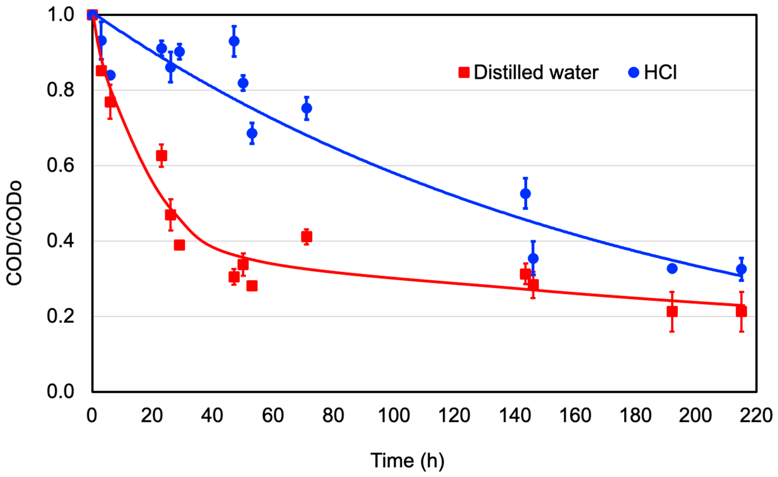
3.1. Biodegradation of Domestic Wastewater

The degradation of organic matter over time, when graphite electrodes were used in the MFC system, is shown in Figure 3 for distilled water and 0.1 M HCl solution. The evolution of COD reduction and anode pH over time is presented. Raw wastewater COD and pH were 533.4 mg/L and 7.8, respectively. When distilled water was used in the cathode chamber, microorganisms’ activity in the anode reduced the COD to 120.00 mg/L (reduction: 77.5%) in 215 h reaction time; observing the greater COD reduction rate in the first 50 h of the experiment. After 50 h reaction time, less organic matter was available, the microorganisms stabilized, entering in a stationary stage with less COD reduction rate. These results agree with those reported by Katuri et al. [42], where the maximum bacterial growth was found in the first 60 h, matching the greatest magnitude of reduction in organic matter in a double-chamber MFC with a graphite anode and platinum cathode separated by a Nafion117® membrane in a batch scenario, reaching its stationary phase at 140 h. Regarding the evolution pH with the time, minimal change was observed, from the initial value of 7.8 to 7.6. The small variations in pH are attributed to the reaction of methane in water due to methanogenic bacteria forming CO and CO2 byproducts.
In the scenario where the HCl was used as a catholyte, a constant COD reduction rate was observed until the end of the experiment, reaching a COD of 180 mg/L (reduction: 66.5%) at 215 h reaction time. It can be noted that if the experiment had been extended for a longer time, the COD reduction could be equal or greater than when distilled water was used. In this scenario, the pH in the anode decreased rapidly until nearly 2 in the first 30 h reaction time due to the diffusion of the HCl through the proton exchange membrane from the cathode to the anode tending to the pH equilibrium in both chambers. The anode’s low pH conditions suppress the methanogens and enrich the electrogens, affecting the COD removal rate, as explained by Jadhav and Ghangrekar [46]; they found that experiments where methanogens were not suppressed performed better COD removal than scenarios where electrogens were the dominant microorganisms in the biofilm, growing around the anode electrode. It was further explained that even if methanogens did not promote power production as electrogens, they did have a higher conversion of organic matter to methane. Further details on the biodegradation process are described by López Zavala et al. [33].

3.2. Influence of the External Resistance on the MFC Performance

The effect of external resistance (Rext) on the energy generation and MFC performance was evaluated considering 10 very different resistances (15, 680, 2 k, 10 k, 15 k, 22 k, 33 k, 47 k, 67 k and 220 kΩ) to reduce the performance variability of the MFC due to the microbiological character of the process and the influence of other operational parameters. As seen in Figure 4, in general, the MFC potential increased as the resistance increased, except for the highest resistance (Rext = 220 kΩ), where the potential was lower than the previous one (Rext = 67 kΩ). Under the Rext = 220 kΩ, the resistance load was too high, therefore limiting the flow of electrons through the circuit, causing a lower response in the current output. Ahigher MFC potential (almost double) was also observed when hydrophilically-treated graphene was used. Furthermore, different potential patterns were observed between scenarios with distilled water and HCl as a catholyte. In the case of distilled water, the MFC potential showed a rapidly decreasing trend; meanwhile, in the scenarios with 0.1 M HCl solution, the MFC potential increased, reaching the maximum, and then decreased gradually. Furthermore, it is evident from the potential patterns that the average potential was greater when the HCl was used as a catholyte. This is explained by the fact that the acidic conditions inhibit the development of methanogens and enrich the electrogens [33]; consequently, the potential is kept more constant and steadier in the MFC. On the other hand, neutral pH conditions favor the development of methanogens that utilize the protons generated to produce methane, thus reducing the transfer of H+ protons to the cathode and then limiting the electrons receptors [46].
In Figure 5, the current generated by the MFC systems over the time is shown for all external resistances evaluated. As observed, the greatest current was obtained at the Rext = 15 Ω for all scenarios and decreased as the external resistance increased due to lower resistance in the external circuit favors the flow of electrons causing a greater response in the current output. This result is in agreement with those reported by the literature in the sense that low external resistances enhance the current generated by the MFC systems [40,41,42,43]. The systems where distilled water and hydrophilically-treated graphene electrodes were used presented initially greater but descendant current intensity; meanwhile, the MFC systems that used HCl as a catholyte produced a more constant and stable current over time.
Regarding energy generation, the best MFC performance was obtained at the Rext = 2 kΩ, as shown in Figure 6. This result also matches with those reported in the literature, in the sense that low external resistances enhance the power produced by the MFC systems [40,41,42,43]. Scenarios that used hydrophilically-treated graphene as electrodes produced significantly more energy than those using graphite. The explanation for this result is that graphene has much higher electrical conductivity than graphite because of its structure. Each carbon atom in graphene is covalently bonded to three others; this atom contains quasiparticles, which are electrons that behave as if they have no mass, causing very high electron mobility that can carry and pass on electric charge [47]. It is important to note that higher external resistances caused greater voltage output or, conversely, the lowest resistance caused the greatest current output; it does not necessarily correlate with the greatest power produced because the greatest power is drawn when external and internal resistances become equal [40,44]. On the other hand, when distilled water and hydrophilically-treated graphene were employed, the energy production of the system was greater than that of the scenario with HCl; however, the energy production rates dropped rapidly over time as seen in Figure 6a, contrary to the case of the HCl catholyte, where the energy production of the MFC system showed an increasing pattern (Figure 6b). This indicated that at longer operation times and greater energy production could be obtained. This can be explained by the slow initial response of the electrochemical active microorganisms under acidic conditions; however, as the reaction time ran, these microorganisms acclimatized and showed steadily increasing activity and energy generation (Figure 6b) that greater energy generation could be expected at reaction times longer than that the used in this study. This fact is confirmed when graphite electrodes were used, where the energy production of the MFC system was much greater when HCl was used as a catholyte (Figure 6c,d). This result was also reported by López Zavala et al. [33], who found that when using the HCl as a catholyte, it diffuses to the anode chamber through the PEM and enhances the liquor conductivity that facilitates the flow of ions through the PEM and electrons through the anodic and cathodic electrolytes. Additionally, the HCl improves the electrode catalysis that reduces the activation losses that occur while the electrons are transferred to the electrode surface from the substrate. Furthermore, the pH < 5 conditions in the anode chamber favor the activity of electrogens that potentialize the transfer of electrons to the anode.
Further analysis was carried out based on the power density curves shown in Figure 7. In this figure, the influence of external resistance on the electricity production of the MFC is much clearer. In general, the greatest power density was obtained at the Rext = 2 kΩ, confirming what was discussed in previous sections in the sense that low external resistances enhance the power produced by the MFC systems [40,41,42,43]. Likewise, it is confirmed that in scenarios where hydrophilically-treated graphene electrodes were used, greater current density was generated. Regarding the influence of the catholyte on electricity production, the greatest power density was obtained when distilled water and hydrophilically-treated graphene were used (Figure 7a). In this case, the maximum power density was 28.23 mW/m2 and 199.49 mW/m3 and the total energy generated through the experiment was 2.643 Wh (9516 J).
For HCl as a catholyte and hydrophilically-treated graphene electrode, the maximum power density obtained was 4.75 mW/m2 and 33.58 mW/m3 and the total energy generated was 1.772 Wh (6379 J). The difference between both scenarios was due to the slow initial response of the electrochemical active microorganisms under acidic conditions; however, as the reaction time running these microorganisms showed a steadily increasing activity and energy generation (Figure 7b), a greater power density could be expected at reaction times longer than the used in this study, such as when graphite was used as a catholyte; the current density was greater when HCl was used as a catholyte. For the scenario with distilled water and graphite electrode (Figure 7c), the maximum power density was 1.85 mW/m2 and 13.09 mW/m3 and the total energy generated through the experiment was 0.037 Wh (133.56 J). For HCl as a catholyte and graphite electrode (Figure 7d), the maximum power density obtained was 2.43 mW/m2 and 17.18 mW/m3 and the total energy generated was 0.431 Wh (1551.60 J).
Figure 8 shows the polarization (potential-current) curves prepared by considering ten different external resistances (15 Ω–220 kΩ) evaluated at the time, in which the greatest power was observed for each scenario. The average internal resistance was calculated as the slope of each polarization curve, resulting in magnitudes of 1.6, 5.5, 6.0, and 4.2 kΩ for the DW-HTG, HCl-HTG, DW-G, and HCl-G scenarios, respectively. As seen, there is not a clear correlation between the internal resistance, the electrode material, and the catholyte. This could be explained by the fact that such polarization curves represent the average effect of all external resistances evaluated at the time at which the potential and current of measurements were conducted for the scenario, thus avoiding observing the effect of the electrode material and the electrolyte chemistry differences on internal resistance. However, based on the overall performance of the MFC system, it is clear that three of the internal resistances obtained are relatively similar among them, on the order of 5 kΩ, and the other resistance is nearly 2 kΩ. By comparing these magnitudes with the external resistance at which the greatest energy and power density were obtained (2 kΩ: Figure 6 and Figure 7), it can be noted that those values are relatively close, even though the external resistance Rext = 5 kΩ was not evaluated in this study. However, it can be assessed from Figure 7 that such external resistance could be within the values that generated the greatest energy and power density of the MFC system. Therefore, it can be confirmed that the greatest power is obtained when the external and internal resistances are equal or in the same order of magnitude. Thus, it can be stated that the external resistance at which the MFC system generates the greatest energy and power density in this study is in the range of 2 kΩ to 5 kΩ.
The influence of the external resistance load, electrode material, and catholyte type on the coulombic efficiency of the MFC system is summarized in Table 1. As seen, the coulombic efficiency decreases as the external resistance increases; thus, the maximum coulombic efficiency was reached at a Rext = 15 Ω in all cases. This result agrees with those reported in the literature, in the sense that low external resistances enhance the performance of the MFC systems [40,41,42,43]; however, operating the MFC system under the optimum coulombic efficiency does not necessarily ensure the greatest power density and energy generation, as confirmed in this study. Regarding the effect of the electrode material on the coulombic efficiency, the MFC system performed best when the HTG was used; in fact, the coulombic efficiency improved by more than 2 orders of magnitude. On the other hand, when HCl was used as a catholyte, the coulombic efficiency was greater in most cases (except for the external resistances 15 and 680 Ω) than when distilled water was used, while it was especially remarkable when graphite electrodes were used. These results confirm that external resistance, electrode material, and catholyte type significantly affect the performance of the MFC system; therefore, external resistance should be reduced at a level that ensures the greatest energy generation and better performance of the MFCs. The use of HTG electrodes and HCl as a catholyte enhanced, in most cases, the coulombic efficiency of the MFC system, therefore its use is recommended.

4. Conclusions

External resistance has an essential role in the performance of microbial fuel cells (MFCs); however, this issue has not received enough attention despite its importance. Therefore, in this study, the influence of external resistance, new carbon-based electrode material, and catholyte type on the performance of microbial fuel cells was evaluated. Greater energy generation and power density were achieved at an external resistance between 2 kΩ and 5 kΩ, where the internal resistance was in the same order of magnitude; meanwhile, the greatest potential and coulombic efficiency were obtained at the lowest external resistance evaluated (15 Ω), irrespective of the electrode material and catholyte type. Therefore, it is recommendable to operate the MFCs at an external resistance that ensures the greatest power density and energy generation, despite sacrificing some of the coulombic efficiency of the dual chamber MFCs. Regarding the two electrode materials evaluated as an anode and cathode, hydrophilically-treated graphene was found to be a much better material to enhance the energy production and performance of the MFC system, independently of the external resistance and the type of catholyte; therefore, its use is recommended in experimental and practical applications. On the other hand, the use of HCl as a catholyte enhanced, in most cases, the performance of MFC (constant and steady potential and greater coulombic efficiency), irrespective of the external resistance and the electrode materials used in this study.

Author Contributions

Conceptualization, M.Á.L.Z.; methodology, M.Á.L.Z. and I.C.C.G.; validation, M.Á.L.Z.; formal analysis, M.Á.L.Z. and I.C.C.G.; investigation, I.C.C.G.; resources, M.Á.L.Z.; writing—original draft preparation, M.Á.L.Z.; writing—review and editing, M.Á.L.Z.; visualization, M.Á.L.Z.; supervision, M.Á.L.Z.; project administration, M.Á.L.Z.; funding acquisition, M.Á.L.Z. All authors have read and agreed to the published version of the manuscript.

Funding

This research received no external funding.

Institutional Review Board Statement

Not applicable.

Informed Consent Statement

Not applicable.

Data Availability Statement

Data is unavailable due to privacy or ethical restrictions.

Acknowledgments

We acknowledge the support received from the National Council of Science and Technology (CONACYT) of Mexico and the Tecnologico de Monterrey.

Conflicts of Interest

The authors declare no conflict of interest.

References

  1. Yang, Y.; Liu, T.; Zhu, X.; Zhang, F.; Ye, D.; Liao, Q.; Li, Y. Boosting Power Density of Microbial Fuel Cells with 3D Nitrogen-Doped Graphene Aerogel Electrode. Adv. Sci. 2016, 3, 1600097. [Google Scholar] [CrossRef] [PubMed]
  2. Logan, B.E.; Hamelers, B.; Rozendal, R.; Schröder, U.; Keller, J.; Freguia, S.; Aelterman, P.; Verstraete, W.; Rabaey, K. Microbial Fuel Cells: Methodology and Technology. Environ. Sci. Technol. 2006, 40, 5181–5192. [Google Scholar] [CrossRef] [PubMed]
  3. Logan, B.E. Microbial Fuel Cells; John Wiley & Sons: Hoboken, NJ, USA, 2008. [Google Scholar]
  4. Koók, L.; Nemestóthy, N.; Bélafi-Bakó, K.; Bakonyi, P. Treatment of dark fermentative H2 production effluents by microbial fuel cells: A tutorial review on promising operational strategies and practices. Int. J. Hydrogen Energy 2021, 46, 5556–5569. [Google Scholar] [CrossRef]
  5. Pushkar, P.; Mungray, A.K. Exploring the use of 3 dimensional low-cost sugar-urea carbon foam electrode in the benthic microbial fuel cell. Renew. Energy 2020, 147, 2032–2042. [Google Scholar] [CrossRef]
  6. Ren, H.; Pyo, S.; Lee, J.-I.; Park, T.-J.; Gittleson, F.S.; Leung, F.C.; Kim, J.; Taylor, A.D.; Lee, H.-S.; Chae, J. A high power density miniaturized microbial fuel cell having carbon nanotube anodes. J. Power Sources 2015, 273, 823–830. [Google Scholar] [CrossRef]
  7. Mohamed, H.O.; Sayed, E.T.; Obaid, M.; Choi, Y.-J.; Park, S.-G.; Al-Qaradawi, S.; Chae, K.-J. Transition metal nanoparticles doped carbon paper as a cost-effective anode in a microbial fuel cell powered by pure and mixed biocatalyst cultures. Int. J. Hydrogen Energy 2018, 43, 21560–21571. [Google Scholar] [CrossRef]
  8. Masoudi, M.; Rahimnejad, M.; Mashkour, M. Fabrication of anode electrode by a novel acrylic based graphite paint on stainless steel mesh and investigating biofilm effect on electrochemical behavior of anode in a single chamber microbial fuel cell. Electrochim. Acta 2020, 344, 136168. [Google Scholar] [CrossRef]
  9. Neto, S.A.; Reginatto, V.; De Andrade, A.R. Microbial Fuel Cells and Wastewater Treatment. In Electrochemical Water and Wastewater Treatment; Elsevier: Amsterdam, The Netherlands, 2018; pp. 305–331. [Google Scholar]
  10. Raccichini, R.; Varzi, A.; Passerini, S.; Scrosati, B. The role of graphene for electrochemical energy storage. Nat. Mater. 2015, 14, 271–279. [Google Scholar] [CrossRef] [PubMed]
  11. ElMekawy, A.; Hegab, H.M.; Losic, D.; Saint, C.P.; Pant, D. Applications of graphene in microbial fuel cells: The gap between promise and reality. Renew. Sustain. Energy Rev. 2017, 72, 1389–1403. [Google Scholar] [CrossRef]
  12. Choi, Y.-J.; Mohamed, H.O.; Park, S.-G.; Al Mayyahi, R.B.; Aldhaifallah, M.; Rezk, H.; Ren, X.; Yu, H.; Chae, K.-J. Electrophoretically fabricated nickel/nickel oxides as cost effective nanocatalysts for the oxygen reduction reaction in air-cathode microbial fuel cell. Int. J. Hydrogen Energy 2020, 45, 5960–5970. [Google Scholar] [CrossRef]
  13. Feng, H.; Liang, Y.; Guo, K.; Chen, W.; Shen, D.; Huang, L.; Zhou, Y.; Wang, M.; Long, Y. TiO2 nanotube arrays modified titanium: A stable, scalable, and cost-effective bioanode for microbial fuel cells. Environ. Sci. Technol. Lett. 2016, 3, 420–424. [Google Scholar] [CrossRef]
  14. Sabirov, I.; Enikeev, N.; Murashkin, M.Y.; Valiev, R.Z. Bulk Nanostructured Materials with Multifunctional Properties; Springer: Heidelberg, Germany, 2015. [Google Scholar]
  15. Baudler, A.; Schmidt, I.; Langner, M.; Greiner, A.; Schröder, U. Does it have to be carbon? Metal anodes in microbial fuel cells and related bioelectrochemical systems. Energy Environ. Sci. 2015, 8, 2048–2055. [Google Scholar] [CrossRef] [Green Version]
  16. Papiya, F.; Das, S.; Pattanayak, P.; Kundu, P.P. The fabrication of silane modified graphene oxide supported Ni–Co bimetallic electrocatalysts: A catalytic system for superior oxygen reduction in microbial fuel cells. Int. J. Hydrogen Energy 2019, 44, 25874–25893. [Google Scholar] [CrossRef]
  17. Santoro, C.; Serov, A.; Stariha, L.; Kodali, M.; Gordon, J.; Babanova, S.; Bretschger, O.; Artyushkova, K.; Atanassov, P. Iron based catalysts from novel low-cost organic precursors for enhanced oxygen reduction reaction in neutral media microbial fuel cells. Energy Environ. Sci. 2016, 9, 2346–2353. [Google Scholar] [CrossRef] [Green Version]
  18. Rajesh, P.P.; Noori, T.; Ghangrekar, M.M. Improving Performance of Microbial Fuel Cell by Using Polyaniline-Coated Carbon–Felt Anode. J. Hazard. Toxic Radioact. Waste 2020, 24, 04020024. [Google Scholar] [CrossRef]
  19. Hu, M.; Li, X.; Xiong, J.; Zeng, L.; Huang, Y.; Wu, Y.; Cao, G.; Li, W. Nano-Fe3C@PGC as a novel low-cost anode electrocatalyst for superior performance microbial fuel cells. Biosens. Bioelectron. 2019, 142, 111594. [Google Scholar] [CrossRef]
  20. Daud, S.M.; Daud, W.R.W.; Abu Bakar, M.H.; Kim, B.H.; Somalu, M.R.; Muchtar, A.; Jahim, J.M.; Ali, S.A.M. Low-cost novel clay earthenware as separator in microbial electrochemical technology for power output improvement. Bioprocess Biosyst. Eng. 2020, 43, 1369–1379. [Google Scholar] [CrossRef]
  21. Hasani-Sadrabadi, M.M.; Dashtimoghadam, E.; Majedi, F.S.; Kabiri, K.; Solati-Hashjin, M.; Moaddel, H. Novel nanocomposite proton exchange membranes based on Nafion® and AMPS-modified montmorillonite for fuel cell applications. J. Membr. Sci. 2010, 365, 286–293. [Google Scholar] [CrossRef]
  22. Das, I.; Das, S.; Sharma, S.; Ghangrekar, M. Ameliorated performance of a microbial fuel cell operated with an alkali pre-treated clayware ceramic membrane. Int. J. Hydrogen Energy 2020, 45, 16787–16798. [Google Scholar] [CrossRef]
  23. Cheraghipoor, M.; Mohebbi-Kalhori, D.; Noroozifar, M.; Maghsoodlou, M.T. Production of greener energy in microbial fuel cell with ceramic separator fabricated using native soils: Effect of lattice and porous SiO2. Fuel 2021, 284, 118938. [Google Scholar] [CrossRef]
  24. Raychaudhuri, A.; Sahoo, R.N.; Behera, M. Application of clayware ceramic separator modified with silica in microbial fuel cell for bioelectricity generation during rice mill wastewater treatment. Water Sci. Technol. 2021, 84, 66–76. [Google Scholar] [CrossRef]
  25. Al Lawati, M.J.; Jafary, T.; Baawain, M.S.; Al-Mamun, A. A mini review on biofouling on air cathode of single chamber microbial fuel cell; prevention and mitigation strategies. Biocatal. Agric. Biotechnol. 2019, 22, 101370. [Google Scholar] [CrossRef]
  26. Zhang, G.; Zhou, Y.; Yang, F. Hydrogen production from microbial fuel cells-ammonia electrolysis cell coupled system fed with landfill leachate using Mo2C/N-doped graphene nanocomposite as HER catalyst. Electrochim. Acta 2019, 299, 672–681. [Google Scholar] [CrossRef]
  27. Florio, C.; Nastro, R.A.; Flagiello, F.; Minutillo, M.; Pirozzi, D.; Pasquale, V.; Ausiello, A.; Toscano, G.; Jannelli, E.; Dumontet, S. Biohydrogen production from solid phase-microbial fuel cell spent substrate: A preliminary study. J. Clean. Prod. 2019, 227, 506–511. [Google Scholar] [CrossRef]
  28. Wang, Y.; Lin, Z.; Su, X.; Zhao, P.; Zhou, J.; He, Q.; Ai, H. Cost-effective domestic wastewater treatment and bioenergy recovery in an immobilized microalgal-based photoautotrophic microbial fuel cell (PMFC). Chem. Eng. J. 2019, 372, 956–965. [Google Scholar] [CrossRef]
  29. Yadav, G.; Sharma, I.; Ghangrekar, M.; Sen, R. A live bio-cathode to enhance power output steered by bacteria-microalgae synergistic metabolism in microbial fuel cell. J. Power Sources 2020, 449, 227560. [Google Scholar] [CrossRef]
  30. Peixoto, L.; Parpot, P.; Martins, G. Assessment of Electron Transfer Mechanisms during a Long-Term Sediment Microbial Fuel Cell Operation. Energies 2019, 12, 481. [Google Scholar] [CrossRef] [Green Version]
  31. Catal, T.; Kul, A.; Atalay, V.E.; Bermek, H.; Ozilhan, S.; Tarhan, N. Efficacy of microbial fuel cells for sensing of cocaine metabolites in urine-based wastewater. J. Power Sources 2019, 414, 1–7. [Google Scholar] [CrossRef]
  32. Rossi, R.; Evans, P.J.; Logan, B.E. Impact of flow recirculation and anode dimensions on performance of a large scale microbial fuel cell. J. Power Sources 2018, 412, 294–300. [Google Scholar] [CrossRef]
  33. Zavala, M.L.; Delenne, P.R.T.; Peña, O.I.G. Improvement of Wastewater Treatment Performance and Power Generation in Microbial Fuel Cells by Enhancing Hydrolysis and Acidogenesis, and by Reducing Internal Losses. Energies 2018, 11, 2309. [Google Scholar] [CrossRef] [Green Version]
  34. Yang, W.; Chata, G.; Zhang, Y.; Peng, Y.; Lu, J.E.; Wang, N.; Mercado, R.; Li, J.; Chen, S. Graphene oxide-supported zinc cobalt oxides as effective cathode catalysts for microbial fuel cell: High catalytic activity and inhibition of biofilm formation. Nano Energy 2019, 57, 811–819. [Google Scholar] [CrossRef]
  35. Boas, J.V.; Oliveira, V.; Marcon, L.; Simões, M.; Pinto, A. Optimization of a single chamber microbial fuel cell using Lactobacillus pentosus: Influence of design and operating parameters. Sci. Total Environ. 2019, 648, 263–270. [Google Scholar] [CrossRef]
  36. Zhao, W.; Ci, S. Nanomaterials As Electrode Materials of Microbial Electrolysis Cells for Hydrogen Generation. In Nanomaterials for the Removal of Pollutants and Resource Reutilization, Micro and Nano Technologies; Luo, X., Deng, F., Eds.; Elsevier: Amsterdam, The Netherlands, 2019; pp. 213–242. [Google Scholar]
  37. Mohan, S.V.; Chiranjeevi, P.; Chandrasekhar, K.; Babu, P.S.; Sarkar, O. Acidogenic Biohydrogen Production From Wastewater. In Biohydrogen; Elsevier: Amsterdam, The Netherlands, 2019; pp. 279–320. [Google Scholar]
  38. Capodaglio, A.G.; Cecconet, D.; Molognoni, D. An Integrated Mathematical Model of Microbial Fuel Cell Processes: Bioelectrochemical and Microbiologic Aspects. Processes 2017, 5, 73. [Google Scholar] [CrossRef] [Green Version]
  39. Koók, L.; Nemestóthy, N.; Bélafi-Bakó, K.; Bakonyi, P. Investigating the specific role of external load on the performance versus stability trade-off in microbial fuel cells. Bioresour. Technol. 2020, 309, 123313. [Google Scholar] [CrossRef]
  40. Aelterman, P.; Versichele, M.; Marzorati, M.; Boon, N.; Verstraete, W. Loading rate and external resistance control the electricity generation of microbial fuel cells with different three-dimensional anodes. Bioresour. Technol. 2008, 99, 8895–8902. [Google Scholar] [CrossRef]
  41. Zhang, L.; Zhu, X.; Li, J.; Liao, Q.; Ye, D. Biofilm formation and electricity generation of a microbial fuel cell started up under different external resistances. J. Power Sources 2011, 196, 6029–6035. [Google Scholar] [CrossRef]
  42. Katuri, K.P.; Scott, K.; Head, I.M.; Picioreanu, C.; Curtis, T.P. Microbial fuel cells meet with external resistance. Bioresour. Technol. 2011, 102, 2758–2766. [Google Scholar] [CrossRef]
  43. Pasternak, G.; Greenman, J.; Ieropoulos, I. Dynamic evolution of anodic biofilm when maturing under different external resis-tive loads in microbial fuel cells, Electrochemical perspective. J. Power Sources 2018, 400, 392–401. [Google Scholar] [CrossRef]
  44. Woodward, L.; Tartakovsky, B.; Perrier, M.; Srinivasan, B. Maximizing power production in a stack of microbial fuel cells us-ing multiunit optimization method. Biotechnol. Prog. 2009, 25, 676–682. [Google Scholar] [CrossRef] [Green Version]
  45. Walter, W.G. Standard Methods for the Examination of Water and Wastewater, 21st ed.; American Public Health Association: Washington, DC, USA, 2005. [Google Scholar]
  46. Jadhav, G.; Ghangrekar, M. Performance of microbial fuel cell subjected to variation in pH, temperature, external load and substrate concentration. Bioresour. Technol. 2009, 100, 717–723. [Google Scholar] [CrossRef] [PubMed]
  47. Geim, A.K.; Novoselov, K.S. The rise of Graphene. Nat. Mater. 2007, 6, 183–191. [Google Scholar] [CrossRef] [PubMed]
Figure 1. Experimental device: Lab-scale MFC. A: negative terminal of the multimeter; B: positive terminal of the multimeter; C: a terminal (-) that connects the resistance´s box to the MFC anode; D: a terminal (-) that connects the amperemeter to the resistance´s box; red cables: positive connectors from the multimeter and amperemeter to the MFC cathode; black cable: negative connector from the multimeter to the MFC node; yellow cable: negative connector from the amperemeter to the resistance´s box; green cable: negative connector from the resistance´s box to the MFC anode.
Fermentation 09 00344 g001
Figure 2. Experimental procedure conducted for each scenario.
Fermentation 09 00344 g002
Figure 3. Degradation of organic matter when graphite electrodes are used in the MFC system. COD reduction.
Fermentation 09 00344 g003
Figure 4. Effect of the external resistance (Ω) on the MFC potential. (a) Water and hydrophilically-treated graphene (DW-HTG); (b) HCl and hydrophilically-treated graphene (HCl-HTG); (c) Water and graphite (DW-G); (d) HCl and graphite (HCl-G).
Fermentation 09 00344 g004
Figure 5. Effect of the external resistance (Ω) on the MFC current. (a) Water and hydrophilically-treated graphene (DW-HTG); (b) HCl and hydrophilically-treated graphene (HCl-HTG); (c) Water and graphite (DW-G); (d) HCl and graphite (HCl-G).
Fermentation 09 00344 g005
Figure 6. Effect of the external resistance (Ω) on the MFC energy generation. (a) Water and hydrophilically-treated graphene (DW-HTG); (b) HCl and hydrophilically-treated graphene (HCl-HTG); (c) Water and graphite (DW-G); (d) HCl and graphite (HCl-G).
Fermentation 09 00344 g006
Figure 7. Effect of the external resistance (Ω) on the MFC power density. (a) Water and hydrophilically-treated graphene (DW-HTG); (b) HCl and hydrophilically-treated graphene (HCl-HTG); (c) Water and graphite (DW-G); (d) HCl and graphite (HCl-G).
Fermentation 09 00344 g007
Figure 8. Polarization curves of the MFC system for ten different external resistances (15 Ω–220 kΩ), two electrode materials, and HCl solution catholyte. HCl: HCl solution as a catholyte; HTG: hydrophilically-treated graphene; DW: distilled water; G: graphite.
Fermentation 09 00344 g008
Table 1. Effect of external resistance, electrode materials, and the catholyte type on the coulombic efficiency (%) of the MFC system.
Resistance (Ω)HTGGraphite
HClDWHClDW
156.269.942.320.07
6805.246.962.070.07
2 k4.744.471.770.07
10 k2.081.361.050.06
15 k1.580.970.820.06
22 k1.150.670.630.05
33 k0.820.460.470.07
47 k0.590.330.350.05
67 k0.420.230.260.03
220 k0.120.070.050.01
HTG: Hydrophilically-treated graphene; HCl: Hydrochloric acid; DW: Distilled water.
Disclaimer/Publisher’s Note: The statements, opinions and data contained in all publications are solely those of the individual author(s) and contributor(s) and not of MDPI and/or the editor(s). MDPI and/or the editor(s) disclaim responsibility for any injury to people or property resulting from any ideas, methods, instructions or products referred to in the content.

