
Galling-Free Fine Blanking of Titanium Plates Using Carbon-Supersaturated High-Speed Steel Punch


1
Surface Engineering Design Laboratory, Shibaura Institute of Technology, Tokyo 144-0045, Japan
2
Hatano Precision, Co., Ltd., Hadano City 257-0015, Japan
*
Author to whom correspondence should be addressed.
C 2023, 9(1), 15; https://doi.org/10.3390/c9010015
Submission received: 28 December 2022
/
Revised: 19 January 2023
/
Accepted: 22 January 2023
/
Published: 25 January 2023
(This article belongs to the Collection Nanocarbon-Based Composites and Their Thermal, Electrical, and Mechanical Properties)
Abstract
:A carbon-supersaturated (CS-) high-speed steel punch was prepared using low-temperature plasma carburizing for fine blanking of pure titanium plates. The bare high-speed steel punch was also prepared as a reference to describe the adhesion and abrasive galling in the fine blanking of the titanium plates, even in a single shot. The CS-punch was free from severe chemical galling, even after repeatedly fine-blanking the pure titanium plates. A microstructure analysis, element mapping and a chemical composition analysis demonstrated that titanium debris fragments slightly deposited at the CS-punch edges in the presence of agglomerated free-carbon film due to the CS-punch. This galling-free fine-blanking behavior came from the in situ formation of free carbon tribofilms. This in situ lubrication resulted in the completely burnished surfaces of pure titanium blanks.
1. Introduction
Fine blanking has been widely utilized in various manufacturing fields, especially in automotive industries [1]. The punched-out product has a fully burnished surface without geometric distortion since the work plate is fixed under the compressive stress state [2]. However, this strict constraint of work plates to the die set, results in the shortage of punch life [3], e.g., the chipping of the punch edge corners, the abrasive wear of the punch edge and the plastic distortion of the punch edge profile. These defects have a direct influence on product quality. The severity of wear at the punch edges is enhanced when fine blanking high-strength ductile metals and alloys. In particular, adhesion wear, or galling, often occurs and significantly shortens the punch life; the fresh fragments of work materials adhere to the punch edges and side surfaces, and their oxide debris particles deposit onto the punch surface [4]. As stated in [4,5], various coatings, including Si-bearing diamond-like carbon (DLC-Si), experience high friction and the sticking of titanium fragments. Most bulk ceramic tools, such as ZrO2, Al2O3, SiC and Si3N4, have no capacity to improve the deep drawability against the titanium sheets [6].
Solid lubrication provides a way to reduce friction and wear in general [7]. Considering that galling occurs at the hot spot under the highly stressed interface between the tool and titanium work materials, the solid lubricants, such as h-BN and graphitic powders, must be deposited to form their tribofilms on those hot spots. In nature, this solid lubrication has a risk of not forming a reliable enough tribofilm to prevent punch and die surfaces from galling [8]. The in situ solid lubrication of carbon-supersaturated (CS-) steel dies has been proposed to reduce the friction and adhesive wear of dies during dry and cold forging, even at a high reduction level of thickness [9,10,11]. Free-carbon solutes diffuse from CS-steel dies, agglomerate themselves and form a free-carbon tribofilm on the hot spots of the contact interface between the CS-tool surface and titanium work material [11,12]. Through this in situ solid lubrication, the low friction and low work hardening of titanium materials have been sustained through the forging process [13,14] and the fine-blanking process [15].
In the present paper, in situ slid lubrication via free-carbon tribofilm formation is investigated in the fine-blanking of thick titanium plates by using CS-high-speed steel punches. Both bare and CS-high-speed punches are prepared for these fine-blanking experiments in order to describe the effect of in situ solid lubrication on the adhesive wear behavior of punches. In particular, Scanning Electron Microscopy (SEM)–Electron-Dispersive X-ray Spectroscopy (EDX) and a chemical component analysis are performed to analyze the contact interface between the CS-punch and titanium work material. The difference in the in situ-formed free-carbon tribofilms caused by the upsetting and fine-blanking processes is discussed to consider the effect of applied stresses during metal forming on in situ solid lubrication.
2. Materials and Methods
A low-temperature plasma carburizing system was utilized for the carbon supersaturation of punches. A fine-blanking system was used to punch out pure titanium plates under normal operating conditions. SEM–EDX and a chemical composition analysis were employed to characterize the tribofilm that was in situ deposited onto the punch surfaces.
2.1. Carbon Supersaturation Process
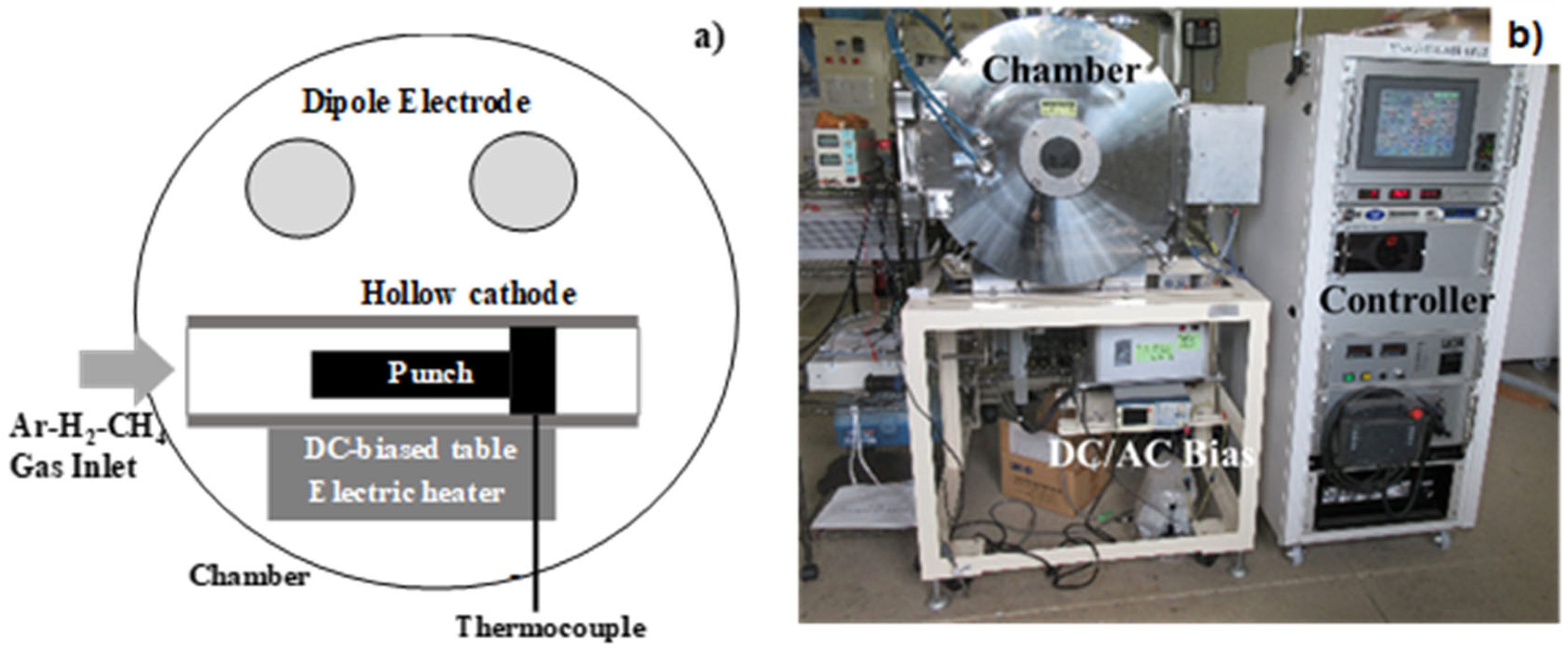
The plasma carburizing system (YS-Electric Industry, Co., Ltd., Kofu, Japan) is schematically illustrated in Figure 1a. The punch was located laterally in the hollow cathode. With reference to the previous studies in [16,17], this hollow cathode device was employed to increase the carbon-ion and CH-radical densities to more than 3 × 10¹⁷ ions/m3 and to increase the carbon-supersaturated layer thickness. This was estimated to be 40 mm in the case of plasma carburizing at 673 K for 14.4 ks by 70 Pa.
Dipole electrodes were utilized to ignite the radio-frequency (RF) plasma, while the direct-current (DC) plasma was also induced by applying the bias voltage to the bottom of the hollow cathode. In the following experiments, the RF voltage and the DC bias were constant at +220 V and −400 V, respectively. After evacuation down to the base pressure of 0.01 Pa, argon gas was introduced into a chamber, as shown in Figure 1b, at room temperature (RT) to clean the punch and die surfaces. After increasing the process temperature to 673 K under the argon atmosphere, hydrogen gas and argon gas were also introduced at flow rates of 20 mL/min and 160 mL/min, respectively. The total pressure was constant at 70 Pa.
After presputtering by the DC plasmas for 1.8 ks, methane gas was introduced as a carbon source into the argon and hydrogen gas mixture at a flow rate of 20 mL/min. At the specified duration of 14.4 ks, the specimen was cooled down in the chamber under a nitrogen atmosphere before evacuation down to atmospheric pressure.
The processing temperature was in situ monitored using a thermocouple, which was embedded into the base plate below the hollow cathode device, as shown in Figure 1a. The total pressure and each flow rate of the argon, hydrogen and methane gasses were also measured for process control. The deviation of temperature and pressure during operation was ± 0.1 K and ± 0.05 Pa, respectively.
Afterward [10,13,14], no iron or chromium carbides were synthesized in the plasma-carburized layer. The peak shift of a-ion to the lower 2q angles in the XRD analysis revealed that the a-lattices in the carburized steels expanded by themselves through the supersaturation of the carbon solutes into steel punches.
2.2. Fine-Blanking System
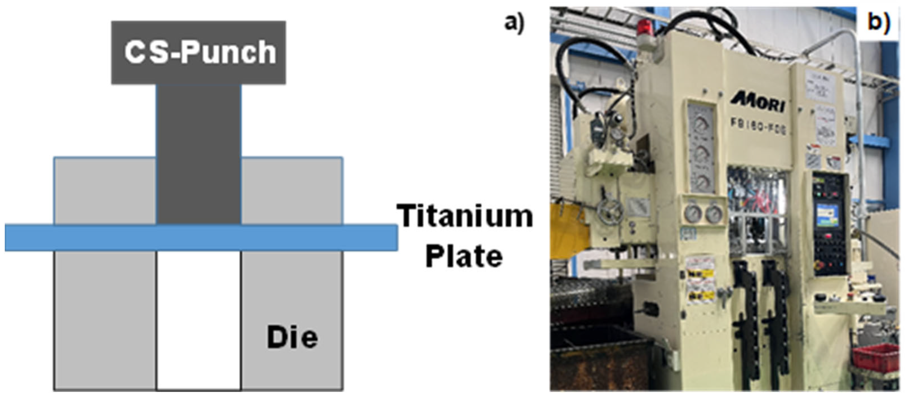
A pure titanium plate with a thickness of 2.0 mm was blanked with a narrow clearance of 4% as illustrated in Figure 2a. A mechanical stamper (FB 160-FDE; Mori Steel Works Co., Ltd.; Saga, Japan), specially accommodated for the fine-blanking process, was used for this experiment, as shown in Figure 2b.
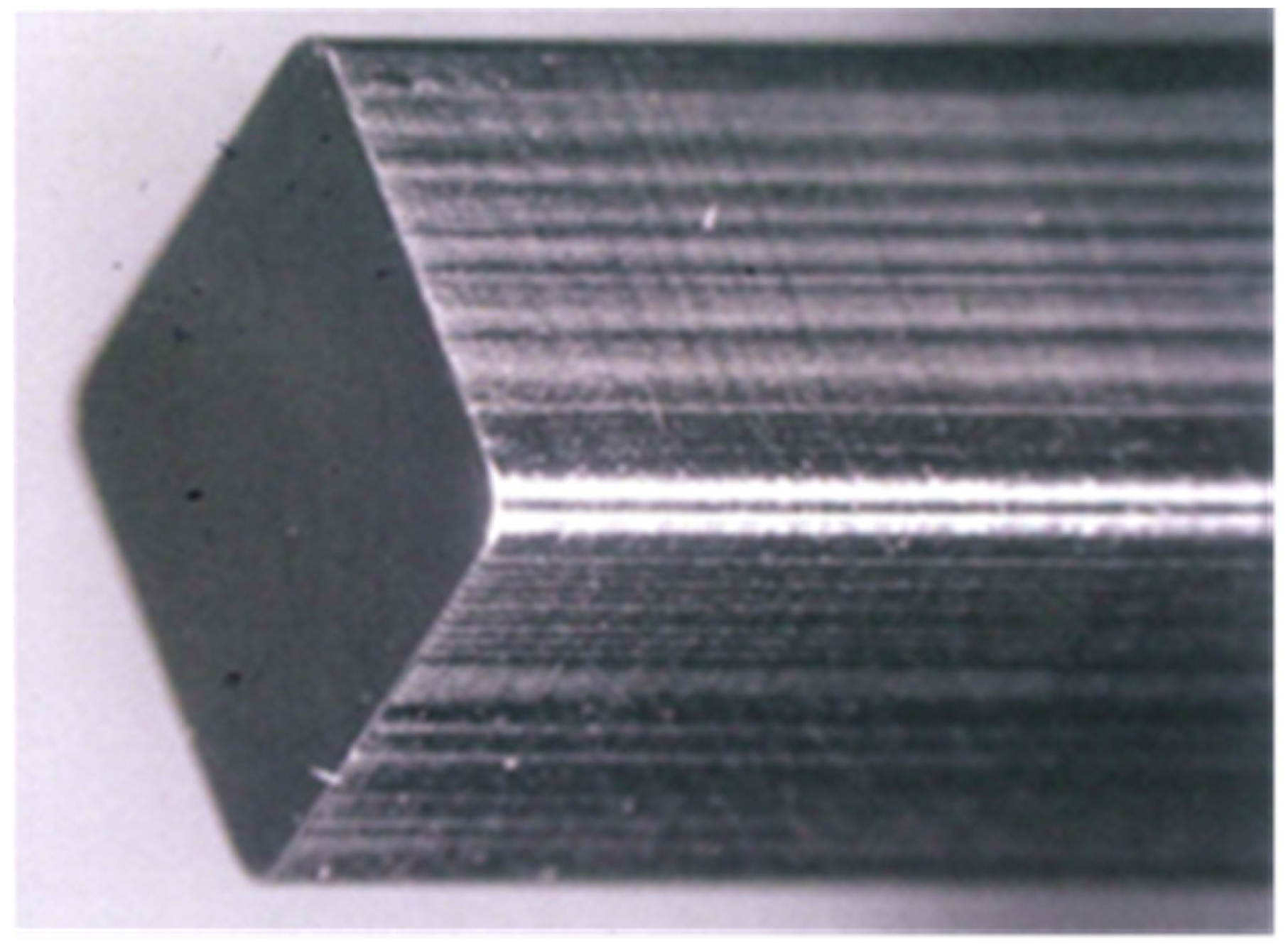
The maximum loading capacity was 1600 kN. The loading sequence for the fine blanking was CNC-programmed. The punches with and without carbon supersaturation were used to describe the effect of the carbon supersaturation on the galling behavior. Each punch was fixed into a punch holder, which was further set up in the upper die set. In the following experiments, FBH9-HMC, with a viscosity of 101 m2/s, was utilized as a lubricating oil. A high-speed steel type YXR7 punch is depicted in Figure 3. This high-speed steel had the following chemical composition: carbon by 0.8 mass%, silicon by 0.8 mass%, manganese by 0.3 mass%, chromium by 4.7 mass%, tungsten by 1.3 mass%, molybdenum by 5.5 mass%, vanadium by 1.3 mass% and iron in balance.
2.3. Materials
Pure titanium wires and plates were utilized as work materials for the upsetting and fine-blanking experiments, respectively. Their chemical compositions consist of hydrogen by 0.0012 mass%, oxygen by 0.097 mass%, nitrogen by 0.007 mass%, iron by 0.042 mass%, carbon by 0.007 mass% and titanium for balance.
2.4. Characterization
SEM–EDX (JOEL, Co., Ltd.; Kanagawa, Japan) was used for a microstructure analysis and element mapping of the contact interface between the forging and fine-blanking tools and the titanium work materials. The chemical components of the tribofilm were analyzed pointwise at the selected positions on the punch side surfaces.
3. Results
Bare and CS-YXR7 punches were utilized for the fine blanking of pure titanium plates. The adhesive wear of titanium fragments deposited onto the punches was compared between the two punches. In particular, the contact interface between the CS-YXR7 punch and the titanium work material was analyzed to describe the formation of free-carbon tribofilms at the contact interface of the CS-YXR7 punch. The punched-out blanks were compared between the two punches to investigate the effect of in situ solid lubrication on the quality of the punched-out blanks.
3.1. Fine Blanking of Pure Titanium Plates Using Bare YXR7 Punch
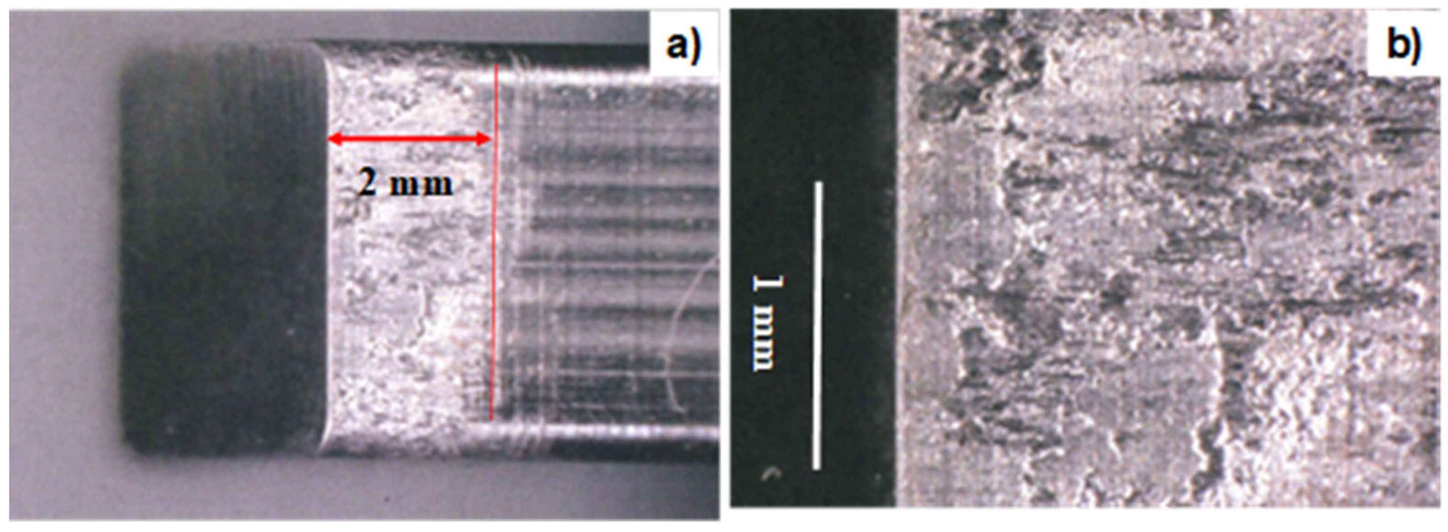
The bare YXR7 punch before fine blanking, as shown in Figure 3, was compared to the punch after the fine blanking of pure titanium plates, with a thickness of 2 mm, in a single shot, as shown in Figure 4. No wear was seen on either of the punch heads after the fine blanking in a single shot. However, their side surfaces, with a length of around 2 mm, were almost covered by the fragments of the titanium work material. In particular, as seen in Figure 4b, the titanium fragments adhered to and eroded into the YXR7 punch, causing detrimental damage to the punch.
It is difficult to ground and polish the debris particles that adhere to the punch surfaces during fine blanking. This galling behavior proves that the freshly sheared titanium work material adheres easily onto punch side surfaces under high normal and shear stress conditions and narrow clearance during fine blanking, even under lubricating conditions. When fine blanking the carbon steels, the lubricating oil worked well to protect the YXR7 punches from abrasive wear, even under the same fine-blanking conditions. This severe adhesive wear is intrinsic to the fine blanking of pure titanium plates.
3.2. Fine Blanking of Pure Titanium Plates Using CS-YXR7 Punch
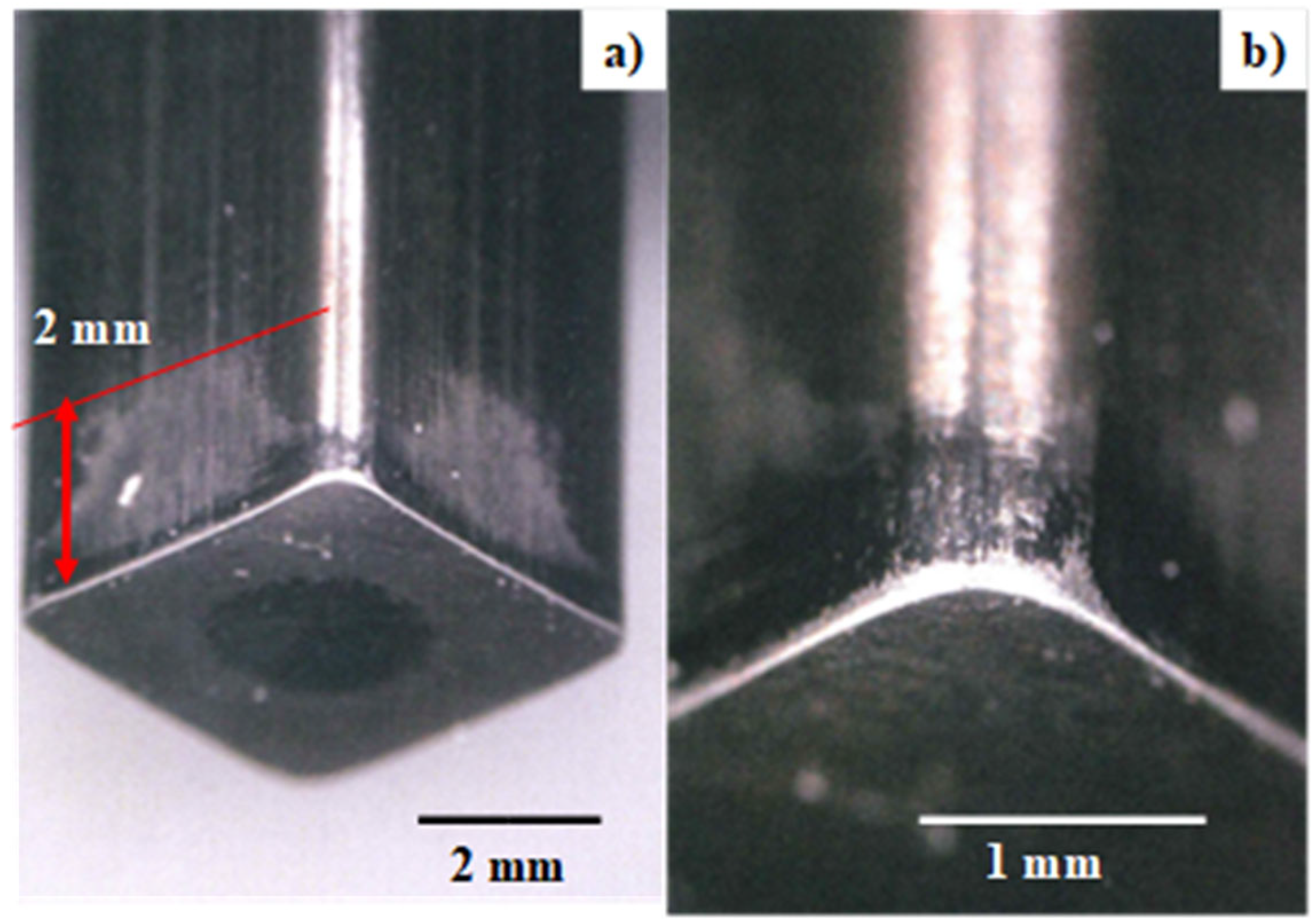
A CS-YXR7 punch was used for the fine blanking of AISI316 plates with a thickness of 3 mm in three shots and then for the fine blanking of pure titanium plates with a thickness of 2 mm in two shots. Figure 5a shows an overview of the CS-YXR7 punch after a series of fine-blanking shots. In contrast to the severe adhesion of titanium fragments to the bare YXR7 punch as shown in Figure 4a,b, the CS-XYR7 punch is completely free from the galling of the sheared titanium work material. As shown in Figure 5a, a thin adhesive film is formed on each side surface only within the region from the punch head to 2 mm away from the punch edge. This implies that a tribofilm formed on the punch side surfaces to prevent them from severe galling by titanium fragments. Figure 5b shows the punch edges and corners after fine blanking. No significant wear was seen on these punch edges and corners.
3.3. SEM-EDX Analysis of the Contact Interface
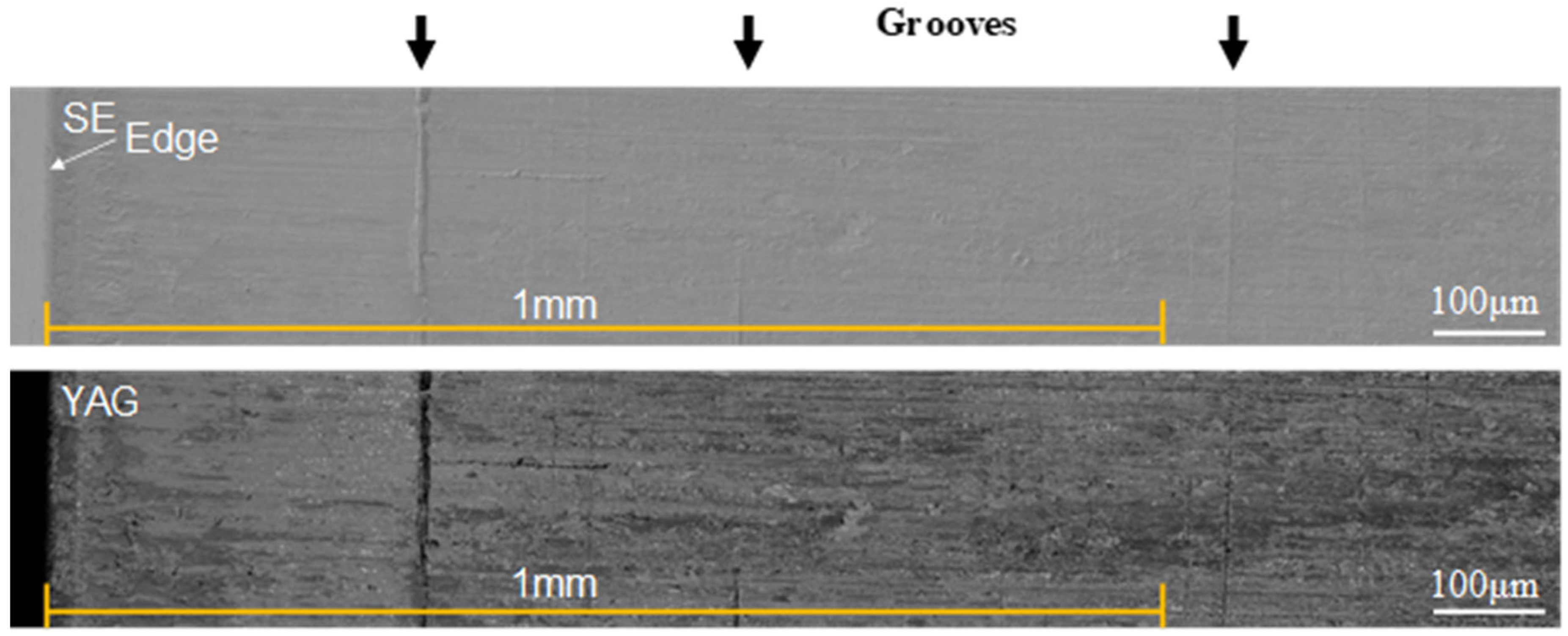
The contact interface between the CS-YXR7 punch and the titanium work material was analyzed by using SEM-EDX to describe the microstructure of the thin tribofilm that formed on the punch side surfaces. At first, SEM and Yttrium Aluminum Garnet (YAG) scintillator images were utilized to describe the tribofilm that formed from the punch edge to a position 1 mm away from this edge. During the fine-blanking process, the punch edge often suffers from hard contact with work materials under high-stress conditions. This SEM-YAG observation around the edge was expected to describe the tribofilm that forms under severe contact conditions. However, the SEM-YAG observation of the middle of the contact interface describes the stationary formed tribofilm under normal and shear stresses.
As depicted in Figure 6, a tribofilm was formed even from the punch edge in the shearing direction on the punch side surface. A few grooves were seen on this surface; these were cut into the tribofilm when the punch was ejected from the punch holder. This suggests that this tribofilm was thin and soft enough to be cut into.
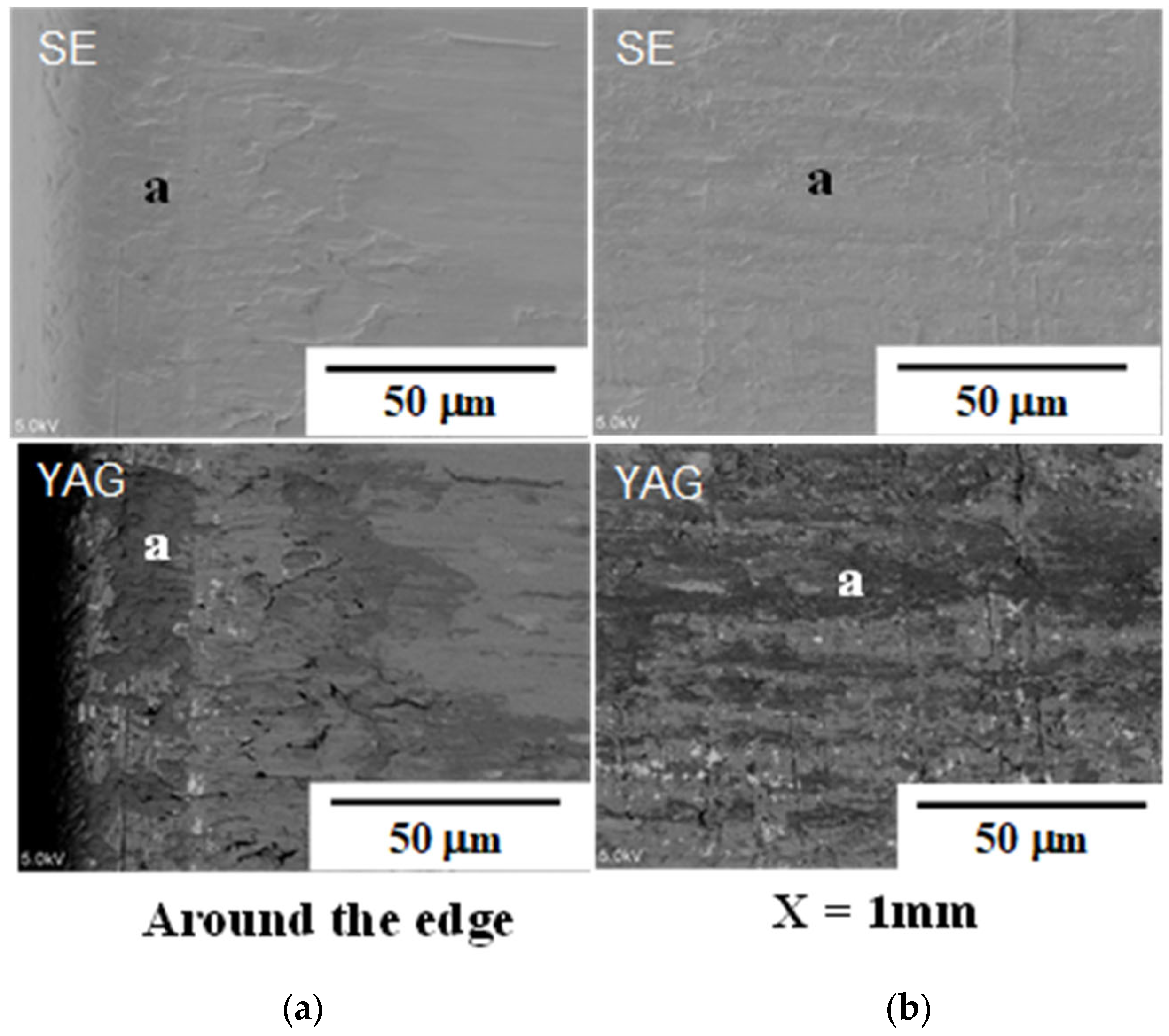
SEM and YAG analyses were performed around the punch edge and at a particular position away from this edge at X = 1 mm. Figure 7 compares the microstructures analyzed at both positions. Adhesive films, indicated by “a” in Figure 7, formed as a layer with a length of 20 mm and a width of 50 mm in the vicinity of the punch edge. This layer formed long stripes, formed along the axial direction or in the X-axis.
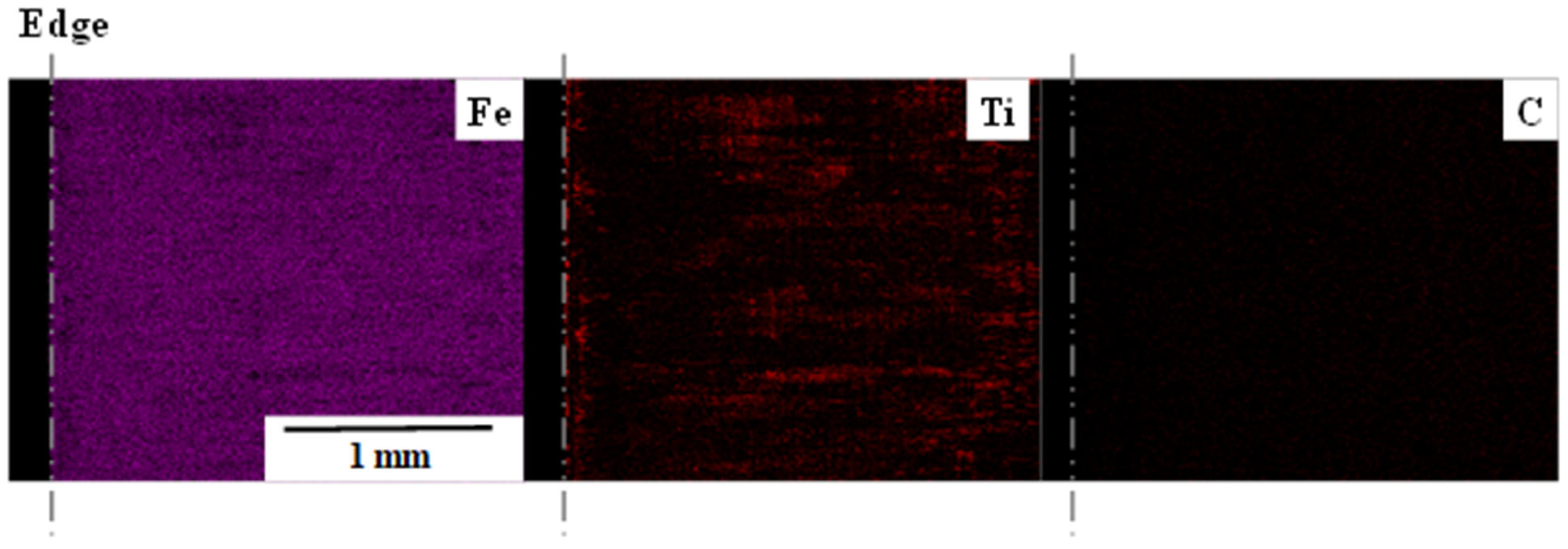
SEM-EDX was also utilized for element mapping. Figure 8 compares the iron, the titanium and the carbon maps of the contact interface. Fine titanium layers were detected in the vicinity of the punch edge. Away from the punch edge, titanium was detected as stripes along the X-axis. Figure 7 and Figure 8 reveal that the black zones, as indicated by “a” in the YAG images, correspond to the titanium maps and that everything apart from the a-zones correspond to the original CS-YXR7 punch side surface. This demonstrates that the adhesion of the titanium debris fragments during the fine blanking was significantly reduced at the contact interface between the CS-YXR7 punch and the titanium work material. The carbon map is also depicted in Figure 8; the carbon concentration was not clearly detected by this wide scanning.
3.4. Chemical Component Analysis
The chemical components were analyzed in the vicinity of the punch edge and at a position 1 mm away from the punch edge at the contact interface between the CS-YXR7 punch and the titanium work material. EDX was also utilized for this pointwise analysis. Table 1 compares the analyzed chemical compositions at both positions with reference to the original chemical compositions of the YXR7 substrate.
Phosphorus, sulfur and nickel were found to be impurities in the analysis. Since the fine blanking was performed at RT in the cold, the oxygen content remained sufficiently low and had nothing to do with the tribofilm formation. A high titanium content was detected in the vicinity of the punch edge; titanium debris fragments adhered to the punch edge. At a position 1 mm away from this punch edge, the detected contents of molybdenum, chromium, vanadium and iron were similar to their original concentrations in the YXR7 substrate, together with a significant reduction in the titanium content. This reveals that the thickness and width of the adhesive titanium layer significantly reduced along the X-direction from the punch edge in accordance with the reduction in the titanium content, as shown in Figure 7 and Figure 8.
Notably, the carbon content increased in the X-direction; a thin carbon film formed on the punch surface. As shown in Figure 6 and Figure 7, this carbon film formed on the punch side surface but not in the a-zones. These films also formed as stripes along the punching direction, together with the thin titanium deposits.
3.5. Estimate of the Tribofilm Thickness
We estimated the free-carbon tribofilm thickness. The original surface roughness of the CS-YXR7-punch was reduced by the formation of a tribofilm on the sheared surface of the punch. Hence, this tribofilm thickness was estimated by measuring the maximum surface roughness on the outside and inside of the sheared punch surface. InfiniteFocusG5 (EuroTechno; Tokyo, Japan) was utilized to measure the roughness profile along the length of 160 mm at positions 1 mm and 5 mm away from the punch edge. The maximum roughness, as an average of the four punch side surfaces, was 0.366 mm at 5 mm and 0.218 mm at 1 mm. The tribofilm thickness was estimated to be around 0.15 mm or 150 nm.
3.6. Quality Evaluation of the Punched-Out Blanks
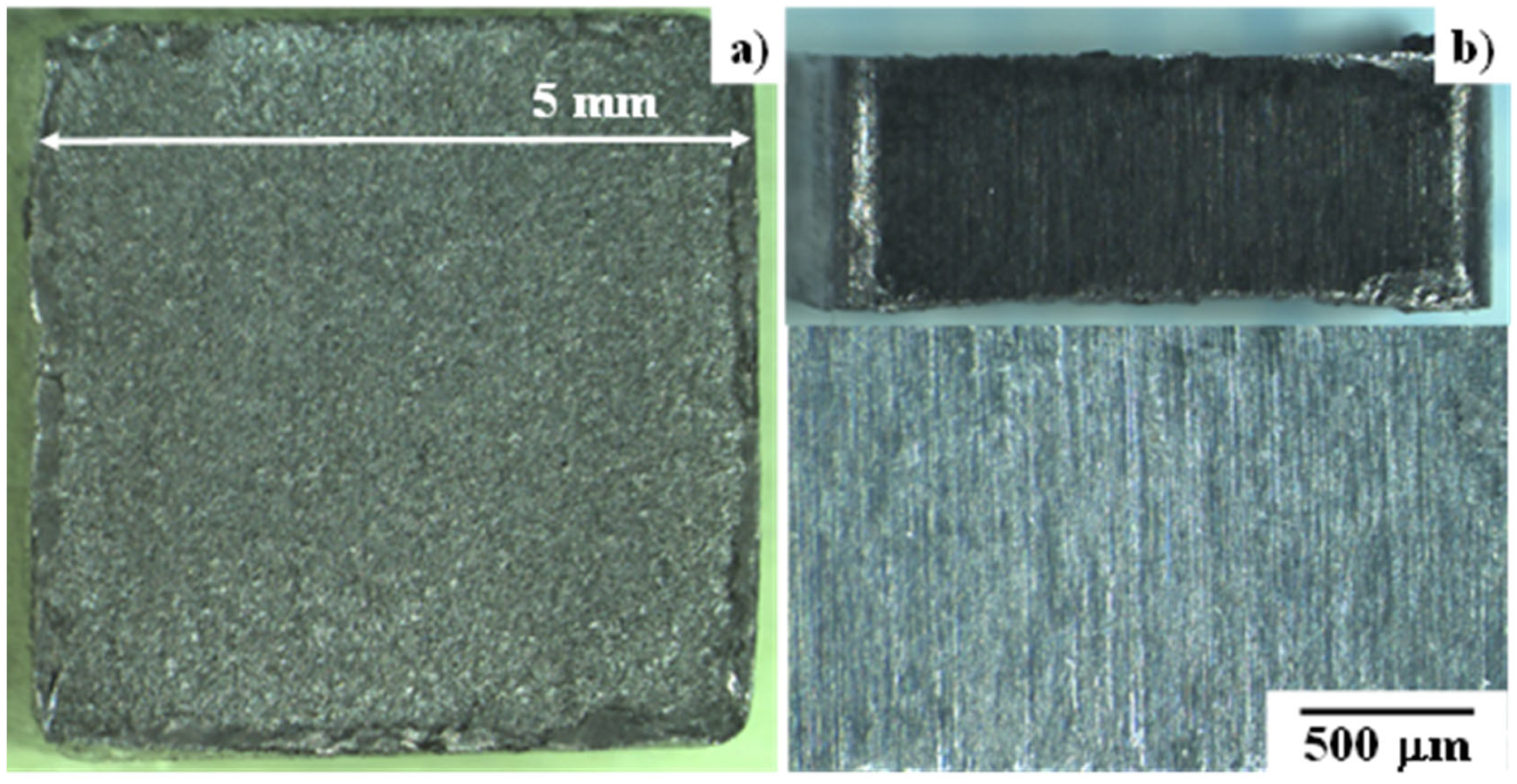
The galling-free behavior suggests that the quality of the punched-out blank is improved by the fine-blanking process. Figure 9 depicts the top and side surfaces of the punched-out titanium blank. No fractured regions are detected on any of the four side surfaces of the blank. This proves that the CS-YXR7 punch is highly qualified and suitable for the fine blanking of titanium plates to produce products.
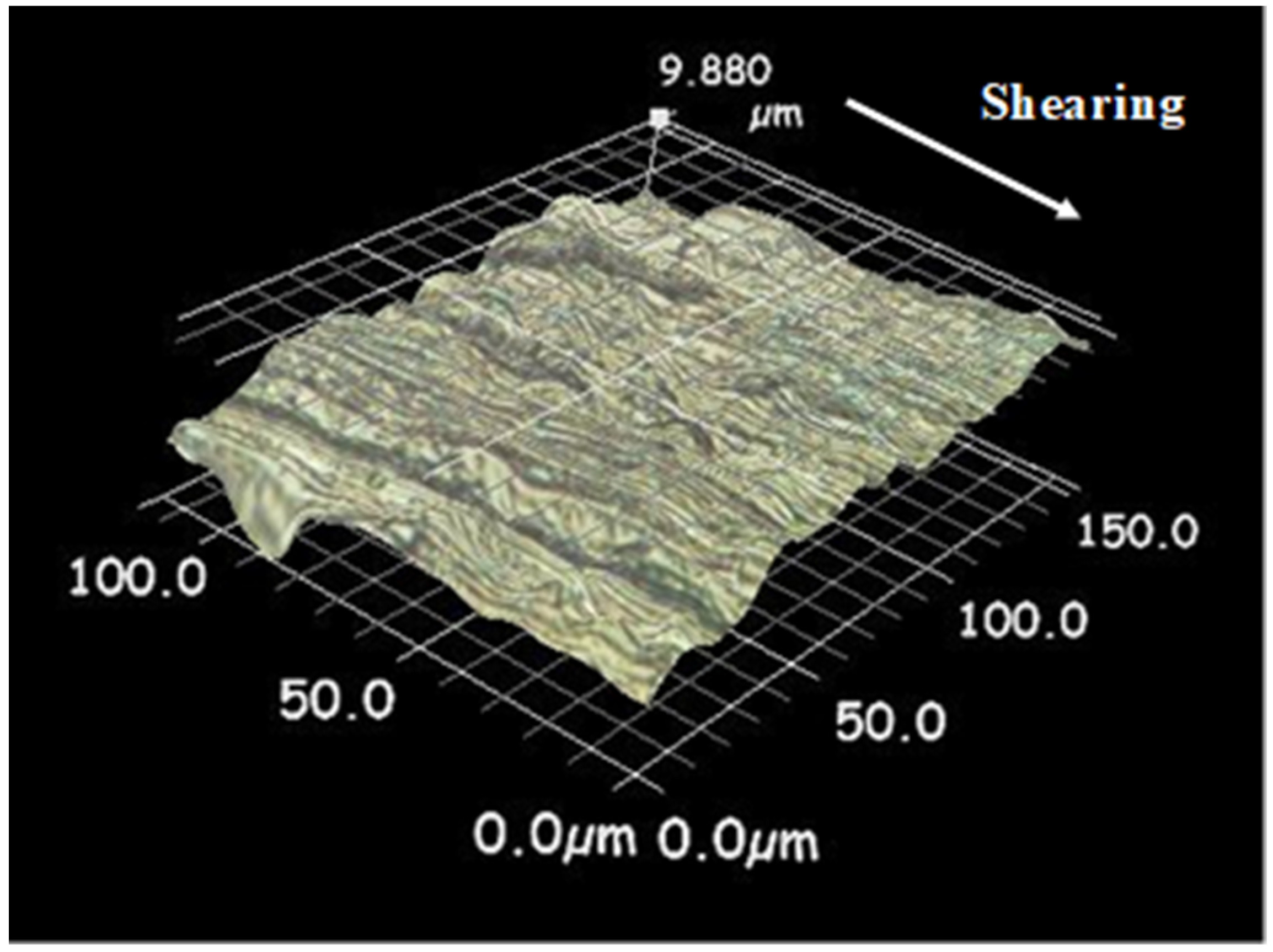
A three-dimensional profilometer (Keyence; Tokyo, Japan) was utilized to measure the surface profile of the sheared surface of the titanium blanks, as shown in Figure 9b. A three-dimensional profile was developed from the measured optical microscopic images. A bird’s eye view of the developed profile is shown in Figure 10. No fractured areas were detected, even at the trace level, by this microscopic analysis of the sheared surface of the titanium blank.
4. Discussion
The fine blanking of titanium and titanium alloys, oxygen-free copper alloys and austenitic stainless steels is considered difficult [18]. Severe adhesive wear caused by the work material debris fragments deposited onto the punch and die is common in the fine-blanking processes of these materials, even under lubricating conditions. As shown in Figure 6, the high-speed steel type YXR7 punch suffered from severe galling with detrimental damage when fine blanking a pure titanium plate with a thickness of 2 mm, even when using lubricating oils. If a solid lubricating tribofilm is not present on the hot spots at the contact interfaces between steel punches and these work materials, severe galling can never be prevented during the fine-blanking process. This is because high shearing and normal stresses applied on the punch side surfaces force titanium debris fragments to adhere to them. The carbon supersaturation of a tool-steel punch and die is a unique solution for the in situ formation of a tribofilm at the contact interface and preventing the punch and die from severe galling.
In conventional solid lubrication, graphite or h-BN powders are deposited or sprayed as a sufficiently thin layer onto the fine-blanking punch surfaces with the appropriate interval of shots. The punch experiences high shearing stress transient in every shot; most of the deposited or sprayed powders are at risk of delamination due to the punch side surfaces inducing partial galling via titanium debris particles. As shown in Figure 5, Figure 6 and Figure 7, a thin film with a thickness of 0.15 mm only formed on the sheared area of the punch side surfaces in this study. This tribofilm worked as a solid lubricating layer throughout the fine-blanking shots without intermission. Since the formed tribofilm was preserved through the fine-blanking process, no additional depositions or sprays were necessary.
As studied in [9,10,11,12,13,14], the free-carbon tribofilm was in situ-formed by the agglomeration of diffusing carbon solutes from the CS-punch and CS-die. A high stress gradient during the dry forging processes induced this carbon solute diffusion and agglomeration. In the fine blanking with a narrow clearance, the CS-punch side surfaces experienced high shearing and normal stress gradients, so the supersaturated carbon solutes in the CS-YXR7 punch diffused to the punch surfaces and agglomerated on the surfaces to form a free-carbon tribofilm.
The free-carbon tribofilm formation analyzed in Figure 7 and Figure 8 and Table 1 is commonly observed in both fine-blanking and forging processes using CS-punches. As stated in [12,13,14], free-carbon layers formed in the direction of the metal flow at the contact interface between the CS-die and the titanium and b-phase titanium alloy work materials. Only carbon agglomerates were detected at the hot spots of the contact interface when using Raman spectroscopy. These findings are also confirmed by the SEM-YAG analyses in Figure 7, the element mapping in Figure 8 and the chemical composition analysis in Table 1. As shown in Figure 4, no iron element, which is a constituent of the YXR7 punch, was detected on the punch surface galled by titanium debris particles. However, the iron element was uniformly distributed on the punch side surfaces in Figure 8; the titanium element was slightly detected in the vicinity of the punch edge. This reveals that the adhesion of the titanium work material fragments was significantly reduced on the CS-YXR7 punch surfaces. Carbon was uniformly distributed on the sheared surface of the punch in Figure 7. After the chemical composition analysis, as shown in Table 1, a higher carbon content was detected on these punch surfaces. Remembering that YXR7 is a low-carbon high-speed steel, this high carbon concentration, detected at the interface between the CS-YXR7 punch and the titanium work material, reveals that free-carbon solute diffused from the CS-YXR7 agglomerates on the highly stressed hot spots at the contact interface and worked as a solid lubricant to protect the YXR7 punch substrate from adhesion wear.
As keenly studied in [13,14], this free-carbon tribofilm works to significantly reduce the friction at the contact interface and to lower the work hardening of titanium and b-phase titanium alloy materials during the forging process with a reduction in thickness higher than 70%. In the case of the fine-blanking process with a CS-punch and die, the friction coefficient also decreases by preventing the adhesion of work material fragments and by preserving the narrow clearance. As shown in Figure 9 and Figure 10, the surface roughness of the ground and polished CS-punch was transcribed onto the blank surfaces without fractured zones. This fully burnished blank surface proves that the low frictional state was preserved during the shearing process of the fine blanking.
DEFORM-3D was utilized to estimate the normal and shear stress distributions in the punch [19]. The punch edge experienced stresses higher than 2750 MPa when fine blanking the AISI304 stainless steels with a thickness of 3 mm. With a narrow clearance during the fine blanking of the titanium plates, as shown in Figure 2, the shearing stress around the YXR7-punch achieved a level equivalent to that of the shear yield stress of titanium.
As discussed in [12], the normal and shear stresses applied to the contact interface drive the supersaturated carbon in the CS-punch to diffuse and agglomerate onto the contact interface. During forging, the normal compressive stress is mainly applied onto the contact interface, the area of which increases with a more severe reduction in thickness. However, normal compressive stress and severe shear stress are also applied to the contact interface, the area of which is constant during fine blanking. This difference in the applied stress level and the geometric configuration must have an influence on the in situ solid lubrication via the free-carbon tribofilm formation. In the free-carbon mapping, free carbon was distinctly detected at the contact interface as a stripe pattern in the case of forging. However, the free carbon was distributed slightly but uniformly at the contact interface in the case of fine blanking. This difference in carbon mapping is due to the normal stress effect on the isolation process of the free-carbon solutes from the CS-YXR7 substrate, as well as the larger contact interface area. That is, the normal stress applied to the contact interface was lower than that applied during forging processes. This lower stress gradient at the interface resulted in a lower content of free-carbon agglomerates on a larger contact area, as demonstrated by the EDX analysis results in Figure 8c, where the free carbon tribofilm was not distinctly detected by EDX in wide scanning.
The fully burnished surface and dimensional accuracy characterize fine-blanked products as suitable for mechanical parts and medical tools. In conventional fine-blanking processes, these most attractive aspects are diminished when fine-blanking high-strength and ductile work materials, such as titanium and titanium alloys, oxygen-free copper alloys and stainless steels. This CS-punch and die technology is expected to provide a new solution to galling-less fine blanking in order to make the net shaping of titanium and titanium alloy gears for robotic arms, to punch out copper electrodes for fuel-cell automotive parts and to yield austenitic stainless-steel pedals for braking units.
5. Conclusions
Carbon supersaturation (CS) in tooling via plasma carburizing at 673 K for 14.4 ks provides a solution to galling-less fine blanking against titanium and titanium alloy work materials, which have been identified as being difficult-to-work materials. A bare high-speed steel punch suffered from severe galling on its side surfaces only after fine blanking in a single shot. The titanium work material fragments adhered to the punch surfaces during severe normal and shearing stresses. Titanium debris fragments were slightly detected only around the CS-punch edges, even after repeatedly fine blanking the titanium plates. A carbon content higher than 3 mass% was detected on the sheared surface of the CS-punch, proving that a free-carbon tribofilm was in situ-formed on the CS-punch side surfaces to prevent the high-speed punch substrate from adhesive wear and to significantly reduce friction and wear damage.
This in situ solid lubrication was reflected in the quality of the punched-out blanks. They were completely free from geometric distortion, which is often induced by galling behavior when fine blanking titanium plates. They had fully burnished surfaces with a well-defined thickness and parallelism, suitable for automotive parts and medical tools. In particular, this geometric accuracy is suitable for lightweight, high-strength gears with a high chemical stability, as well as bio-compatible medical tools.
Author Contributions
Conceptualization, T.A. and K.F.; methodology, T.A.; software, K.F.; validation, T.A. and K.F.; formal analysis, K.F.; investigation, T.A. and K.F.; resources, T.A. and K.F.; data curation, K.F.; writing—original draft preparation, T.A.; writing—review and editing, T.A. and K.F.; visualization, K.F.; supervision, T.A.; project administration, T.A.; funding acquisition, K.F. All authors have read and agreed to the published version of the manuscript.
Funding
This research received no external funding.
Data Availability Statement
Not applicable.
Acknowledgments
The authors would like to express their gratitude to S. Kobayashi (Hatano Precision, Co., Ltd.) for his help in the fine-blanking experiments and to Y. Aihara, S. Hirabayashi and Y. Suzuki (Komatsu-Seiki Kosakusho, Co., Ltd.) for their help in the analyses.
Conflicts of Interest
The authors declare no conflict of interest.
References
- Kuhlman, G.W. Forging of Titanium Alloys. In Metalworking: Bulk Forming; ASM International: Novelty, OH, USA, 2005; Volume 14. [Google Scholar]
- Chandrasekaran, M. Forging of metals and alloys for biomedical applications. In Metals for Biomedical Devices, 2nd ed.; Woodhead Publishing: Sawston, UK, 2019; pp. 293–310. [Google Scholar]
- Nielsen, C.V.; Martins, P.A.F. Metal Forming: Formability, Simulation and Tool Design; Elsevier: Amsterdam, The Netherlands, 2021. [Google Scholar]
- Kihara, T. Visualization of deforming process of titanium and titanium alloy using high speed camera. In Proceedings of the Japanese Society of Technology of Plasticity, Kyoto, Japan, 9 June 2019; pp. 41–42. [Google Scholar]
- Dohda, K.; Aizawa, T. Tribo-characterization of silicon doped and nano-structured DLC coatings by metal forming simulators. Manuf. Lett. 2014, 2, 82–85. [Google Scholar] [CrossRef]
- Kataoka, S.; Murakawa, M.; Aizawa, T.; Ike, H. Tribology of dry deep-drawing of various metal sheets wit use of ceramic tools. Surf. Coat. Technol. 2004, 174, 582–590. [Google Scholar] [CrossRef]
- Hutchings, I.; Shipway, P. Tribology: Friction and Wear of Engineering Materials, 2nd ed.; Elsevier: Oxford, UK, 2017. [Google Scholar]
- Dohda, K.; Yamamoto, M.; Hu, C.; Dubar, L.; Ehman, K.F. Galling phenomena in metal forming. Friction 2020, 9, 686–696. [Google Scholar] [CrossRef]
- Aizawa, T.; Yoshino, T.; Suzuki, Y.; Shiratori, T. Anti-galling cold dry forging of pure titanium by plasma carburized AISI420J2 dies. Appl. Sci. 2021, 11, 595. [Google Scholar] [CrossRef]
- Aizawa, T.; Yoshino, T.; Suzuki, Y.; Shiratori, T. Free-forging of pure titanium with high reduction of thickness by plasma carburized SKD11 dies. J. Mater. 2021, 14, 2536. [Google Scholar] [CrossRef] [PubMed]
- Aizawa, T.; Ishiguro, S.; Shiratori, T.; Yoshino, T. Near-net forging of titanium and titanium alloys by the plasma carburized SKD11 dies. Key Eng. Mater. 2022, 926, 1143–1150. [Google Scholar] [CrossRef]
- Aizawa, T.; Shiratori, T. In situ solid lubrication in cold dry forging of titanium by isolated free carbon from carbon- supersaturated dies. Friction, 2022; in press. [Google Scholar]
- Ishiguro, S.; Aizawa, T.; Funazuka, T.; Shiratori, T. Green forging of titanium and titanium alloys by using the carbon supersaturated SKD11 dies. J. Appl. Mech. 2022, 3, 724–739. [Google Scholar] [CrossRef]
- Aizawa, T.; Funazuka, T.; Shiratori, T. Near-net forging of titanium and titanium alloys with low friction and low work hardening by using carbon-supersaturated SKD11 dies. Lubricants 2022, 10, 203. [Google Scholar] [CrossRef]
- Aizawa, T.; Fuchiwaki, K.; Dohda, K. Galling-free fine blanking of titanium plates by carbon-supersaturated tool steel punch. In Proceedings of the 26th ESAFORM, Krakof, Poland, 18–21 April 2023. in press. [Google Scholar]
- Aizawa, T. Low Temperature Plasma Nitriding of Austenitic Stainless Steels. In Stainless Steels and Alloys; IntechOpen: London, UK, 2019; pp. 31–50. [Google Scholar]
- Geobel, D.M.; Becatti, C.; Mikellides, I.G.; Ortega, A.L. Plasma hollow cathodes. J. App. Phys. 2021, 130, 050902. [Google Scholar] [CrossRef]
- Adamus, J.; Lacki, P.; Wieckowaski, W.; Tytanowych, D.B. Numerical simulation of the fine blanking process of sheet titanium. Arch. Metall. Mater. 2011, 56, 431–437. [Google Scholar] [CrossRef] [Green Version]
- Fuchiwaki, K. Edge profile control of the fine blanking punches. In Proceedings of the 348th Symposium on the Metal Forming, Tokyo, Japan, 1 December 2022; pp. 21–26. [Google Scholar]
Figure 1.
Carbon supersaturation processing system using low-temperature plasma carburizing: (a) schematic view of the carbon supersaturation into steel punches and (b) overview of the plasma carburizing system.
Figure 1.
Carbon supersaturation processing system using low-temperature plasma carburizing: (a) schematic view of the carbon supersaturation into steel punches and (b) overview of the plasma carburizing system.

Figure 2.
Fine-blanking system: (a) schematic view of the fine-blanking process and (b) overview of the fine-blanking system.
Figure 2.
Fine-blanking system: (a) schematic view of the fine-blanking process and (b) overview of the fine-blanking system.

Figure 3.
High-speed steel type YXR7 punch for fine blanking the square hole.

Figure 4.
The bare YXR7 punch just after fine blanking a pure titanium plate with a thickness of 2 mm in a single shot: (a) overview of the bare YXR7 punch and (b) XYR7 punch side surface with severe adherence of titanium fragments.
Figure 4.
The bare YXR7 punch just after fine blanking a pure titanium plate with a thickness of 2 mm in a single shot: (a) overview of the bare YXR7 punch and (b) XYR7 punch side surface with severe adherence of titanium fragments.

Figure 5.
The CS-YXR7 punch after fine blanking AISI304 plates with a thickness of 3 mm in three shots and pure titanium plates with a thickness of 2 mm in two shots: (a) overview of CS-YXR7 punch after fine blanking and (b) the punch edges and punch corner.
Figure 5.
The CS-YXR7 punch after fine blanking AISI304 plates with a thickness of 3 mm in three shots and pure titanium plates with a thickness of 2 mm in two shots: (a) overview of CS-YXR7 punch after fine blanking and (b) the punch edges and punch corner.

Figure 6.
SEM and YAG images of the punch side surface from the punch edge to a position 1 mm away from this.
Figure 6.
SEM and YAG images of the punch side surface from the punch edge to a position 1 mm away from this.

Figure 7.
SEM and YAG images of the punch side surface with a higher magnification around the punch edge and at x = 1 mm from this edge: (a) SEM and YAG images around the punch edge and (b) SEM and YAG images at x = 1 mm from the punch edge.
Figure 7.
SEM and YAG images of the punch side surface with a higher magnification around the punch edge and at x = 1 mm from this edge: (a) SEM and YAG images around the punch edge and (b) SEM and YAG images at x = 1 mm from the punch edge.

Figure 8.
Element mapping of the punch side surface around the punch edge.

Figure 9.
Observation of the sheared square blank using the CS-YXR7 punch: (a) top view of punched-out titanium blank and (b) side surface of punched-out titanium blank.
Figure 9.
Observation of the sheared square blank using the CS-YXR7 punch: (a) top view of punched-out titanium blank and (b) side surface of punched-out titanium blank.

Figure 10.
Three-dimensional surface profile of the sheared square blank using the CS-YXR7 punch.


Table 1.
Comparison of the chemical compositions analyzed in the vicinity of the edge and at a position 1 mm away from the punch edge at the contact interface between the CS-YXR7 punch and the titanium work material, with reference to the chemical compositions of the bare YXR7.
Table 1.
Comparison of the chemical compositions analyzed in the vicinity of the edge and at a position 1 mm away from the punch edge at the contact interface between the CS-YXR7 punch and the titanium work material, with reference to the chemical compositions of the bare YXR7.
| Chemical Element | In the Vicinity of Punch Edge (mass%) | 1 mm Away from the Edge (mass%) | Bare YXR7 Substrate (mass%) |
|---|---|---|---|
| Carbon | 1.49 | 3.38 | 0.8 |
| Oxygen | 0.58 | 0.60 | --- |
| Silicon | 0.20 | 0.59 | 0.8 |
| Tungsten | 2.62 | 6.65 | 1.3 |
| Phosphorous | 0.02 | 0.06 | --- |
| Molybdenum | 1.63 | 3.48 | 5.5 |
| Sulfur | 0.13 | 0.23 | --- |
| Titanium | 34.67 | 4.31 | --- |
| Vanadium | 0.76 | 1.42 | 1.3 |
| Chromium | 3.40 | 3.94 | 4.7 |
| Manganese | 0.07 | 0.24 | 0.3 |
| Iron | 53.99 | 75.03 | 85.3 |
| Nickel | 0.44 | 0.06 | --- |
Disclaimer/Publisher’s Note: The statements, opinions and data contained in all publications are solely those of the individual author(s) and contributor(s) and not of MDPI and/or the editor(s). MDPI and/or the editor(s) disclaim responsibility for any injury to people or property resulting from any ideas, methods, instructions or products referred to in the content. |
© 2023 by the authors. Licensee MDPI, Basel, Switzerland. This article is an open access article distributed under the terms and conditions of the Creative Commons Attribution (CC BY) license (https://creativecommons.org/licenses/by/4.0/).
Share and Cite
MDPI and ACS Style
Aizawa, T.; Fuchiwaki, K. Galling-Free Fine Blanking of Titanium Plates Using Carbon-Supersaturated High-Speed Steel Punch. C 2023, 9, 15. https://doi.org/10.3390/c9010015
AMA Style
Aizawa T, Fuchiwaki K. Galling-Free Fine Blanking of Titanium Plates Using Carbon-Supersaturated High-Speed Steel Punch. C. 2023; 9(1):15. https://doi.org/10.3390/c9010015
Chicago/Turabian StyleAizawa, Tatsuhiko, and Kenji Fuchiwaki. 2023. "Galling-Free Fine Blanking of Titanium Plates Using Carbon-Supersaturated High-Speed Steel Punch" C 9, no. 1: 15. https://doi.org/10.3390/c9010015
Note that from the first issue of 2016, this journal uses article numbers instead of page numbers. See further details here.