
Experimental Study on the Interaction of an Impulse Water Jet with Molten Metal

Ishlinsky Institute for Problems in Mechanics RAS, 119526 Moscow, Russia
*
Author to whom correspondence should be addressed.
Fluids 2023, 8(6), 166; https://doi.org/10.3390/fluids8060166
Submission received: 31 March 2023
/
Revised: 16 May 2023
/
Accepted: 23 May 2023
/
Published: 25 May 2023
(This article belongs to the Section Flow of Multi-Phase Fluids and Granular Materials)
Abstract
:The impingement of a short-duration water jet on a pool of molten Rose’s metal is studied experimentally herein. Short-duration water jet impacting on the free surface of a molten metal pool with a temperature of 300 °C are generated with a pneumatic water delivery system, with two-camera high-speed video registration. A total of 14 experimental series, each containing 5 repeated tests, are performed for a water volume of 0.2–1 mL and a jet impact velocity of 4.1–9.0 m/s. The cavity development in the melt layer is studied, with the main stages described herein. Despite the significantly higher density of melt in comparison with water, the cavity can reach the melt pool bottom; furthermore, its further collapse results in the formation of a central jet rising to the height of a few centimeters. The maximum height of the central jet is shown to depend linearly on the total momentum of the water jet, and a semi-logarithmic correlation is found for the maximum diameter of the cavity. Repeatability analysis is performed within each experimental series, and the relative standard deviation for the melt splash height is shown to be from 8.8% to 26.8%. The effects of the pool depth, the vessel shape, and the water temperature are weaker in the range of the experimental parameters used here.
1. Introduction
The impingement of liquid droplets and jets on the free surface of the same or different liquid has been the subject of extensive research over the past century, starting with the pioneering works of Worthington [1]. The interaction of the impinging and target liquids is characterized by fast momentum, energy, and mass redistribution, causing the splashing of fast, tiny droplets and the formation of the Rayleigh (central) jet, which rises above the impingement point [2,3,4]. In particular, it was established that parameters such as the depth of the target fluid layer, the viscosity, and the surface tension play an important role in the cavity development and central jet formation.
Although the main features and regimes of the drop–liquid-layer interactions are known quite well [5,6], there is still room for studying the fine flow structures that develop in the interaction zone [7,8] for mixing and non-mixing liquids, including liquid metals at room temperatures [9].
Related studies on droplet impingement on solid surfaces are of high applied value, in particular, on those that are hot. This type of fluid dynamic and thermal interaction is important in areas such as spray cooling, falling-film evaporation, ink jet printing, etc. [10,11]. Even isothermal droplet interaction with a dry surface exhibits numerous spectacular modes, including spreading, deposition, rebound, merging, splashing of different kinds, etc. [12].
Liquid jet impingement on a solid surface finds many applications as an effective method of surface cooling. In this respect, numerous studies have been performed in order to establish the effect on heat transfer enhancement of factors such as the shape of the jet and target surface, the fluid properties (including their modification with nanoparticles), the nozzle design, etc. Recent comprehensive reviews of the theoretical and experimental findings, as well as available correlations, can be found in papers [13,14].
While there exists a plethora of works on the impingement of droplets on the surface of the same (or those with a similar density) liquid, much less studied are such interactions when a volume of lower-density liquid impinges on the surface of a much heavier liquid (say, water–liquid metal interactions). Of particular importance are such interactions when hydrodynamic aspects coexist with thermal ones, as is the case when water interacts with the high-temperature melt of some metal or nuclear material (corium). It is of no surprise that so-called “fuel–coolant interactions,” or FCIs, constitute an integral part of severe-accident analysis in the nuclear industry. The rapid evaporation of coolant upon contact with high-temperature molten material can lead to vapor (or steam) explosions, which are considered as one of the major hazards of severe accidents [15].
Vapor explosions are complex processes involving such stages as premixing (the formation of a three-phase mixture, where melt, coolant, and coolant vapor are mixed in some proportion), triggering, thermal detonation propagation, and the subsequent expansion of debris and accelerated coolant. Detailed studies of such events are complicated because of their short duration, high pressure loads, limited visibility in water due to obscuration by debris, etc. Therefore, separate-effects studies are helpful to understand the physics and the fluid dynamics of the processes involved.
One of the FCI types are so-called stratified steam explosions, occurring when a layer of hot molten material spreads over a shallow water pool. An important question arising in such a configuration is on the physical mechanism responsible for the development of a premixed zone where a self-sustained thermal detonation wave can propagate. In the experimental work [16], it was observed that melt spreading is accompanied by sporadic melt splashes rising to the height of a few centimeters. It was argued that these splashes could be initiated by impacts of water micro-jets occurring either due to the collapse of vapor bubbles or due to the development of Rayleigh–Taylor instability on the water–vapor interface above the melt. Therefore, it is important to study the details of melt interaction with an impinging water jet, which is the primary goal of the current paper.
We consider a particular problem amenable to treatment in small-scale experiments, focusing on the splashing of hot melt caused by the impingement of a single short-duration water jet. The problem in question is different from the well-studied similar issues in the following respects: (i) water jet geometry is very different from nearly spherical droplets, (ii) the interaction proceeds over a longer time frame than in the case of a falling droplet, (iii) no mixing between the impinging and target liquids is possible because the target liquid is at the temperature above the boiling point of the impinging liquid, and (iv) the target liquid density is an order of magnitude higher than that of the impinging liquid.
First attempts to study melt splashing caused by an impact of impulse water jets and falling droplets were undertaken in our previous works [17,18], where a small number of scoping experiments were performed. The results obtained highlighted many interesting features of the interaction, including the formation of melt splashes and central jets similar to those in water–water interactions, the fine fragmentation of water and melt, and the scattering of very fine melt droplets (observed as solid particles after freezing). Relevant numerical simulations of melt–water interactions were reported in [19,20].
The present work is devoted to the study of short-duration water jet impacting on the free surface of a molten metal pool. Experiments are performed for the melt-to-water density ratio about 10:1, unlike the much better studied systems (water–water, water–ink, water–glycerin, liquid metal–liquid metal, etc.), where this ratio is about 1:1. This research significantly extends the recent scoping study on water–metal interactions [17,18] by improving the water-jet parameter repeatability and studying the effects of the melt vessel shape, the molten pool depth, and the water temperature. Its novelty is also attributed to the detailed study of the fluid dynamics of the cavity formation and collapse in the melt layer. The repeatability analysis performed sheds light on the intrinsic variability of the melt splashes occurring under the same initial conditions. Free-falling water droplets, also considered in [17,18], were not studied further in the current work because their impact caused much weaker melt splashes due to the high melt–water density ratio.
2. Materials and Methods
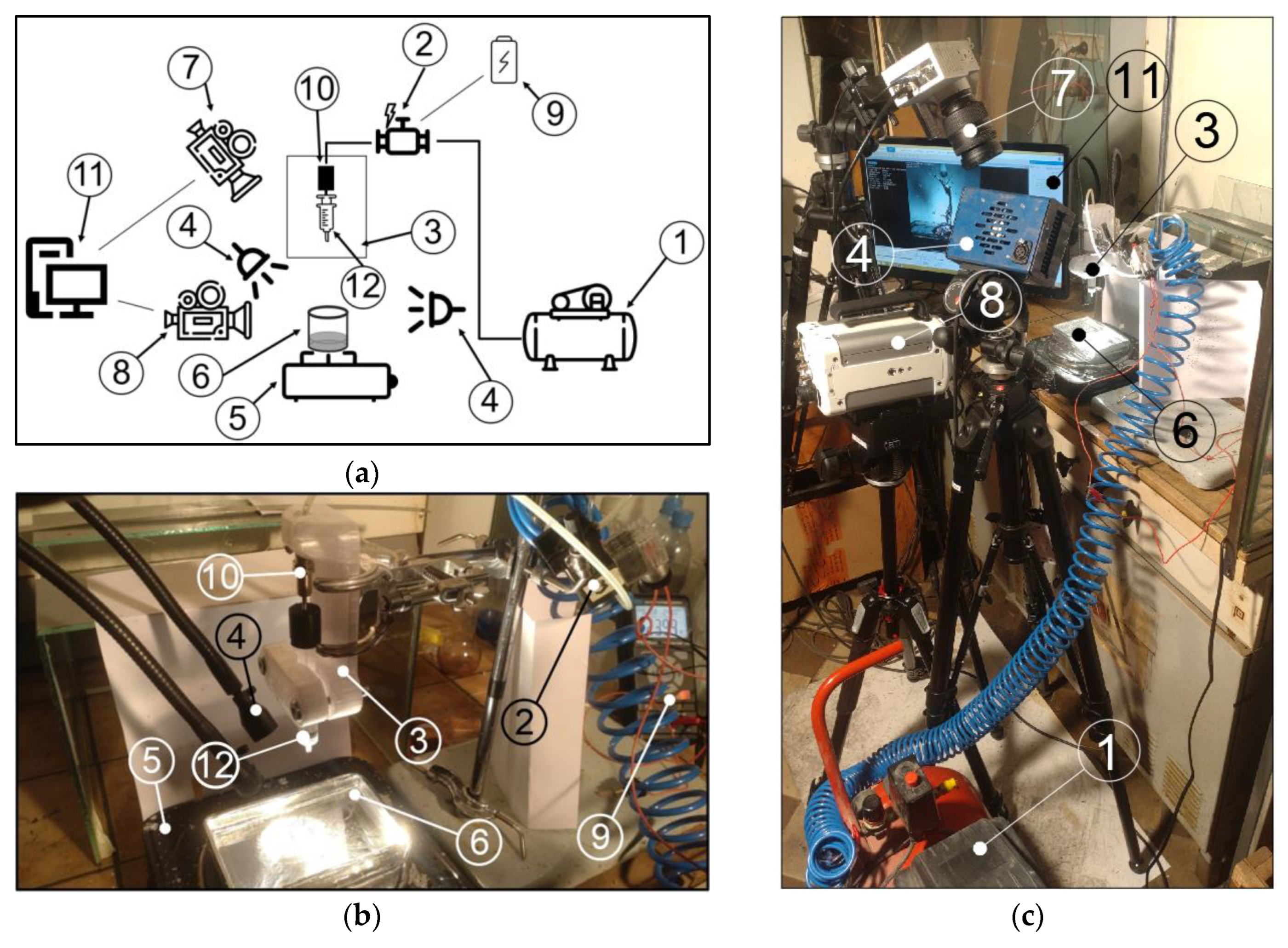
The experimental facility used in the current study is shown in Figure 1a (sketch) and Figure 1b,c (photos from two different views). The key element of the facility is the water delivery system, designed with the purpose of providing reproducible parameters of water jets, including the water volume and impact velocity, and reducing the uncertainties related to manual water supply from a hand-held syringe in our previous work [17,18]. The core element of the delivery system is the pneumatic actuator (10) driven by the compressor (1), with a receiver volume of 24 L and maximum pressure 0.8 MPa. The pressurized air line is connected to the actuator through a cutoff valve (2) powered by a 24 V DC source (9). The pneumatic actuator is connected rigidly to the syringe plunger by a spacer, and the syringe (12) is held in a plastic holder manufactured by 3D printing that can accommodate syringes of various sizes. The pneumatic actuator has a thread on its cylindrical body that allows one to adjust the volume of liquid in the syringe (12) by screwing the pneumatic cylinder into its seat on the holder (3).
The molten material is held in a vessel (6) located centrally under the syringe and heated from below by a 2-kW electric heater (5). In order to study the effect of the pool surface area and vessel shape, experiments were performed in two types of vessels. The majority of experiments were performed with a cylindrical vessel of 84 mm diameter and 23 mm depth; in addition, a rectangular-shaped vessel of 140 mm × 90 mm × 25 mm size (L × W × H) was used. The depth of the molten metal pool was nominally equal to 18 mm; however, a series of experiments was performed with a 14-mm-deep pool in order to evaluate the effect of the melt layer thickness on the splash parameters.
In the experiments, molten Rose’s metal heated to a temperature of 280–320 °C was used as the high-temperature liquid. The properties of Rose’s metal are summarized in Table 1. It can be seen that the melt was superheated with respect to its melting point by 126–226 °C (and by 120–220 °C, with respect to water normal boiling point).
Since the melt-free surface was in contact with the air, a very thin frozen film formed there with time. To avoid the influence of this film on the melt–water interaction, the melt surface was cleared and refreshed with an aluminum scoop prior to each test.
The experiments were performed with water at 20 °C, and two sets of tests were carried out where the initial water temperature was varied (45 °C and 90 °C). Ordinary tap water was used in all experiments; however, its chemical composition, presence of impurities, etc., were not controlled because it seems unlikely that these subtle details play any role in the processes considered herein.
The following two types of syringes were used in the experiments: (i) a smaller one with a nominal volume of 2 mL and piston diameter of 8.8 mm and (ii) a larger one with a 5 mL capacity and piston diameter of 11.8 mm. For both syringe types, the nozzle had a diameter of 2 mm, and its outlet was located at an elevation of 90 mm above the melt pool surface. This height was found to be optimal in the preliminary experiments; on one hand, it is sufficient for a water jet to form, and, on the other hand, it is short enough to prevent the jet breakup into separate droplets due to capillary instability.
The water jet velocity was controlled by varying the pressure in the compressor receiver. A preliminary set of experiments was carried out in order to determine the velocity–pressure dependence; furthermore, the corresponding graph for the smaller syringe is plotted in Figure 2 (note that the pressure in the receiver is measured from the atmospheric pressure, therefore, it is the overpressure, rather than the absolute value). It can be seen that velocity increases linearly with pressure in the compressor receiver, which simplifies the setting of the desired jet parameters.
Two cameras were used to record the melt–water interaction development. The first one, Optronis CR3000x2 (manufactured by Optronis GmbH, Kehl, Germany), see position (7) in Figure 1, was installed on a tripod at an angle of 60° to the horizontal plane, and it provided a top view of the interaction zone. The second one, Photron FASTCAM Nova S9 (manufactured by Photron Ltd, Tokyo, Japan), see position (8) in Figure 1, was installed at an angle of 5° to provide the front view. Both cameras were connected to computers (11) to control the recording and save the video files. The software supplied with the cameras by respective manufacturers (Photron FASTCAM Viewer ver. 4.0.6.2 for FASTCAM Nova S9 and TimeBench ver. 2.6.30 for Optronis CR3000x2) was used to control the video settings and video data acquisition. In each experiment, the video cameras were turned on for recording manually, after which the pneumatic valve was started with a push-button switch. The synchronization of the video recordings from both cameras was carried out by searching for a frame corresponding to the instant when the water jet touched the surface of the melt.
In all of the experiments, recording was performed at a frame rate of 4000 FPS at a fixed resolution of 512 × 512 pixels for the Optronis CR3000x2 (7) and 1024 × 1024 pixels for the Photron FASTCAM Nova S9 (8). The recorded video files obtained in each individual experiment were then split into separate frames, of which the most informative ones were further processed in Autodesk AutoCAD 2021. By using the standard image processing tools, the actual water jet velocity was calculated using the coordinates of the leading jet point between five successive images. In the same way, the height of the melt splash, and other parameters of interaction, were determined. The linear scale was obtained using the visible sizes of the syringe and melt vessel.
When determining the height of the central jet or the coordinates of the extreme points of the cavity and its diameter, some uncertainty was introduced due to the melt surface irregularities and the smearing of visible melt edges due to the finite frame rate. For the image resolution of 1024 × 1024 pixels covering the field of view of about 12 cm, the absolute error in the point coordinates was about 0.12 mm (1 pixel). At a shooting rate of 4000 frames per second, and maximum fluid speeds of up to 5 m/s (typical of the experiments considered in the following sections), the error in the positions determined from the image did not exceed about 1.3 mm. For the typical length scale of the flow elements that are of interest in the current research (about 50 mm), the relative error was as low as 3%. Note, however, that such blurring occurred only in the areas of the highest flow speeds, whereas the smearing of the melt boundary near the highest rise point of the central jet or cavity was weaker, not exceeding one to two pixels, which gave an estimate of the relative coordinate error of less than 1%.
3. Results and Discussion
3.1. Experimental Parameters
The experimental program that was followed in the current work significantly extends the scoping experiments on water jet and droplet interaction with molten Rose’s metal reported earlier [17]. The experimental matrix is presented in Table 2, and it was designed to cover a wider range of conditions, including those that were not considered in the previous work [17]. The leftmost column of Table 2 lists the acronyms of cases, while the other columns contain the air pressure in the compressor receiver controlling the injection velocity, the water volume and temperature in the syringe, the melt temperature and depth, and the shape of the vessel with the molten metal (round or rectangular).
A total of 14 different cases (denoted in Table 2 as J1–J14) were studied experimentally. In order to evaluate the repeatability of the results and estimate the aleatory uncertainty, experiments in each case (J1–J14) were repeated 5 times; therefore, a total of 70 experiments were carried out. The video recordings of each individual experiment were processed in order to obtain the splash characteristics, such as the central jet rising height, the cavity size and depth, etc. (“raw” data). After that, averaging over the five experiments was performed in each case in order to obtain the mean values and the standard deviations characterizing the uncertainty.
Note that in cases J2–J4 and J6–J8, the smaller syringe with a nominal volume of 2 mL and a piston diameter of 8.8 mm was used, whereas, in all of the other cases, the experiments were performed with a larger syringe of 5 mL capacity and a piston diameter of 11.8 mm. Due to the difference in the piston area and the volume of water, the water jet velocities that were generated by the larger syringe were about 1.8 times higher at the same pressure than in the case of the smaller syringe.
3.2. Main Features of Melt–Water Interaction upon Impulse Jet Impact
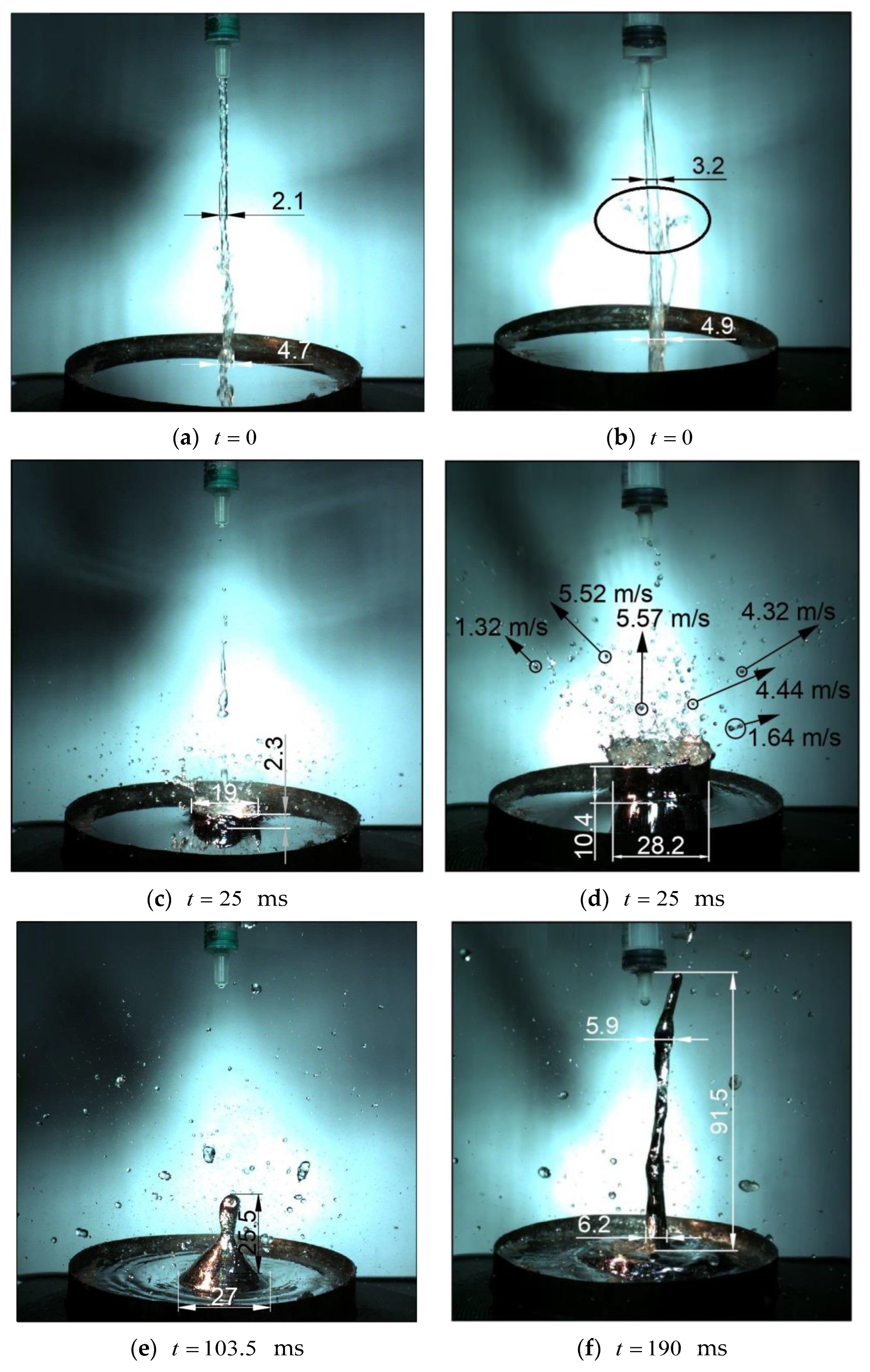
To elucidate the main features and differences observed, we compared the results that were obtained in the test with a moderate jet velocity of 5 m/s and a water volume of 0.4 mL (one of the tests belonging to the set of five experiments performed with the same parameters, named J6) and the test with the highest water jet velocity of 9.41 m/s and water volume of 1 mL (which belongs to the set of five experiments of J1 in Table 2).
In Figure 3, the different stages of the water–melt interactions observed in the two tests are shown at three characteristic instants. Figure 3a,b show the water jet at the time when the jet just touches the melt surface (this instant is taken as in both cases). The water jet generated by the smaller syringe (case J6) was more perturbed than the faster and thicker water jet in case J1 due to the development of capillary-driven (Plateau–Rayleigh) instability [23]. In the latter case (Figure 3b), the jet boundary at the instant just before the impact was quite smooth, except for the jet “head” where Rayleigh–Taylor instability developed due to the drag-induced water deceleration. Here, thin water film stripped off the jet leading edge due to its interaction with the air was clearly visible (indicated by an oval line in Figure 3b). The perturbations on the leading edge of the water jet added more randomness to the jet impact on the melt surface, in comparison with the gravity-accelerated water drops considered in [17].
The impact of water jet on the melt surface resulted in the development of an expanding cavity, with the melt surface moving downwards by inertia, and the displaced melt thrown upwards as a thin film, with the upper edge featured by small melt droplets forming a “crown.” The stronger impact of the faster jet (see Figure 3d) resulted in a higher crown than that observed for the slower water jet (Figure 3c). Both of the figures correspond to time ms. In addition, significant fragmentation of water into dispersed droplets was visible in both cases.
Since the melt temperature is higher than the boiling temperature of water at normal pressure, it can be expected that the water can only be in direct contact with the melt for a very short time, after which a vapor film separating the two liquids appears, limiting the heat exchange rate between them. The size and shape of the cavity depend on the momentum transferred to melt by the impacting water jet; however, this quantity must depend on the water jet’s total momentum proportional to the product of the water density, volume, and velocity. From the data given above, it can be concluded that the water momentum in case J1 was times higher than that of case J6. Accordingly, the cavity shown in Figure 3d has a larger diameter (28.2 vs. 19 mm) and height (10.4 vs. 2.3 mm) than that shown in Figure 3c. The cavity depth is not seen in Figure 3, but it can be assumed that a deeper cavity was generated by the stronger jet impact. This question will be further considered in the subsequent sections. In addition, fine (sub-millimeter) melt droplets that were thrown away from the impact site at velocities of up to 5 m/s can be seen in Figure 3d, which were absent in the case of weaker jet impact (Figure 3c). These droplets, also observed in our previous experiments [17,18], contributed to the fine melt fragmentation during the interaction with water. The smoother cavity edge in case J6 indicates that the effects of surface tension played a more important role for the weaker water jet impact.
The collapse of the cavity in the melt that was caused by the gravity force resulted in the appearance of the known central jet, as shown in Figure 3e,f, at the instants of maximum rise. It can be seen that the stronger impact (Figure 3f) resulted in a thinner and taller central jet, whereas, for the weaker impact (Figure 3e), the jet rise was much lower, and the jet had a peculiar shape with a rather wide “skirt” joining the jet to the pool. This shape indicates that some air or water vapor was captured by the collapsing cavity, resulting in the formation of an internal gas bubble under the melt surface. The different shapes and heights of the central jets obtained in the experiments will be analyzed below. We note here that poor repeatability of the central jet shapes was also obtained in our earlier scoping experiments [17,18] with the same pair of liquids (water and Rose’s metal).
3.3. Influence of Water Volume and Jet Velocity
Here, we consider the results of the experiments performed under the conditions listed in Table 2. Recall that each row in Table 2 corresponds to a set of five experiments carried out for the same experimental parameters. In this way, it was possible to evaluate the repeatability of the melt splashing characteristics, such as the central jet height and velocity, as well as the maximum cavity diameter.
In Table 3, the measured quantities averaged over the five repeated experiments are presented. All of the experiments were conducted with melt contained in a round cylindrical vessel at a constant melt pool depth of 18 mm and melt temperature of 300 °C.
In order to evaluate the repeatability of the experiments, each averaged measured value in Table 3 (calculated as ) was supplemented by its standard deviation (calculated as ) and relative standard deviation (in percentage), given in the bottom line of each row (the water volume and air pressure were well-controlled and were not considered as stochastic variables, and the deviation presented for the measured water velocity is omitted for the calculated jet momentum and kinetic energy). Here, are the measured values and is the number of measurements in each set. Note that the relative standard deviations in Table 3, characterizing the randomness of the melt splashing, were much larger than the relative errors that were introduced by the image processing procedure (see estimates in Section 2).
The results presented in Table 3 support the idea of water jet momentum as the primary parameter governing the central jet height, velocity, and maximum cavity diameter. In Figure 4a, the “raw” (not averaged) data are plotted for each set of five experiments in Table 3. In Figure 4b, eight points corresponding to the average data for each experiment are plotted, with the scatter indicated by the error bars. The straight line in each graph corresponds to the linear function obtained as the best fit to the “raw” data, as follows:
where is the averaged central jet rise height, is water jet’s total momentum, and is the proportionality coefficient obtained by the least-square method (the adjusted coefficient of the determination for this line is ). All of the quantities in (1) are measured in SI units.
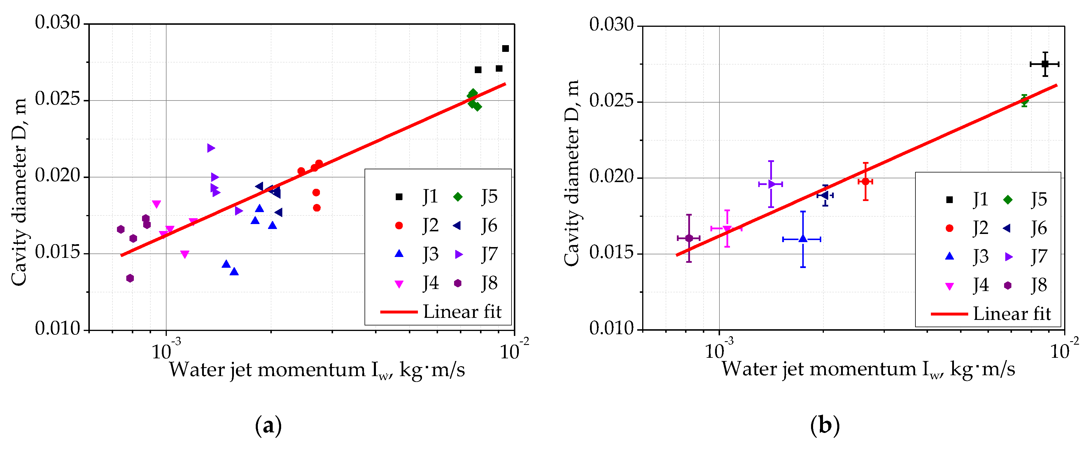
A similar approach was applied to the data on the maximum cavity diameter , which are plotted against the water jet momentum in Figure 5a,b (“raw” and averaged data, respectively). In this case, however, the following logarithmic best-fit approximation was found:
where , (all of the quantities are measured in SI units). The functional form of Formula (2) is not encountered in any of theoretical works considering the splashing by droplet impact (e.g., [2,5]); therefore, it must be regarded for the moment as purely empirical, awaiting more mechanistic treatment and the development of an appropriate model for the water jet impact on a high-density melt surface.
The linear dependence (see Equation (1)) is different from that predicted by a theory of drop impingement on a surface of a pool of the same liquid [2], where it was found that the central jet height scales were , where the Froude number is , with being an equivalent droplet diameter. This dependence gives the central jet height proportional to the square root of the impact velocity. A proper non-dimensional scaling for the impingement of an impulse jet of a light liquid on a finite-depth (shallow) layer of much heavier liquid has yet to be derived, even in an idealized problem formulation. Its validation would also require a wider experimental database, with a wider range of melt pool depths, water jet diameters, etc.
3.4. Influence of Melt Pool Depth and Vessel Shape
The effect of the pool depth on the cavity and the central jet geometry has been studied quite extensively, so far only in the case of water droplets impinging on the water surface, i.e., when the densities of the impacting and receiving liquids are close to each other. It was shown that, for water–water interactions, when the pool is shallow (when its depth is comparable with the diameter of the falling droplet), the cavity growth and decay, as well as the central jet rising height, are different from those in a deep pool. For example, it was shown in [24,25,26,27] that, when a drop of water interacts with water as a target fluid, the height of the central jet reaches its maximum value at a liquid layer depth equal to 6–9 mm (for a droplet diameter of 2.3–4.1 mm, respectively). If the target fluid depth increases to more than 9 mm, or decreases to less than 6 mm, the maximum height of the central jet decreases. In [26], it was found that the optimal depth of the liquid should be equal to the cavity diameter in order to reach the maximum height of the central jet.
In this work, the system studied was different from the above-mentioned works in the following two aspects: (i) the density ratio was higher by an order of magnitude (the receiving liquid was much heavier than the impacting one) and (ii) the impact occurred due to impingement of an impulse jet, rather than a single droplet. Another question arising from the analysis of melt splashes is the influence of the melt vessel shape, which can affect the cavity formation and cause subsequent collapse, leading to the central jet formation.
In order to study the effect of the pool depth and vessel shape on melt splashing, a series of four experiments named J9–J12 (shown in Table 2) was performed. As mentioned previously, each acronym in Table 2 denotes a set of five experiments performed sequentially for the same input parameters. The results obtained are presented in Table 4.
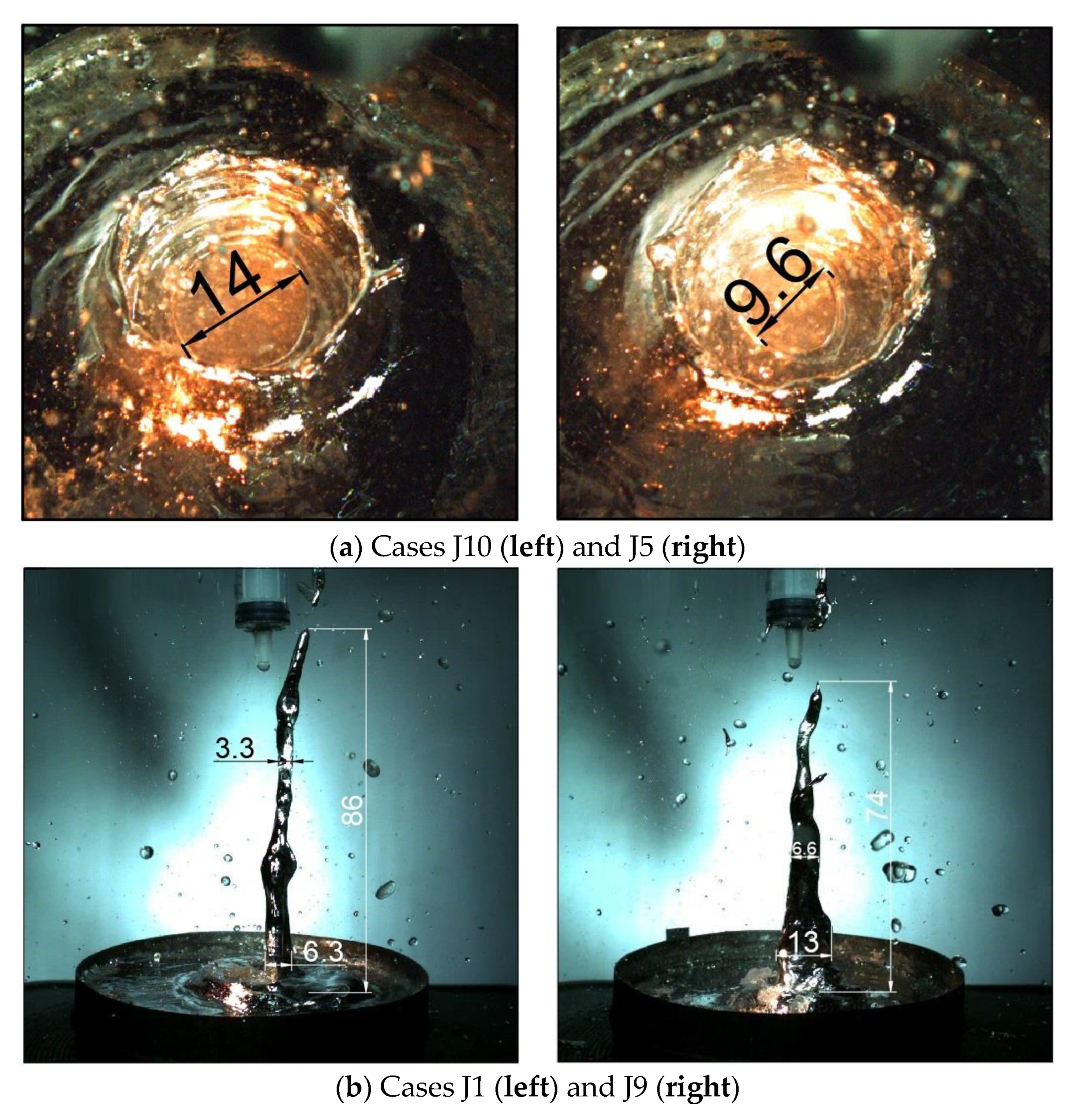
It is interesting to analyze the features of melt cavity geometry after the termination of the water jet impact. Figure 6a shows the resulting cavity in two cases, J5 and J10, that differ only in the melt pool depth.
As can be seen, the cavity was divided into two parts by a narrow “neck,” with a diameter of 14 mm for case J10 and 9.6 mm for case J5. This neck serves as an obstacle during the formation of the central jet, which leads to some loss of the initial jet momentum obtained from collapse of the lower part of the cavity. In case J5, the neck diameter was smaller than that of case J10; however, this practically did not influence the height of the central jet, which was 4.2 mm taller in case J10. In cases J1 and J9, similar cavity shapes with the neck were observed, but the central jet in case J1 turned out to be thin and high, whereas, in case J9, the jet was lower and thicker (Figure 6b). This agrees well with the conclusion of work [25], where it is stated that the central jet turns out thicker and lower if the pressure gradients become parallel to the pool bottom.
We consider now, in more detail, the shape of the cavity in the cases shown above. When a water jet with a high momentum penetrates through the whole depth of the melt layer, reaching the pool bottom, a cavity is formed, somewhat similar in shape to the sand clock, with a narrow neck between the parts. The upper cavity part, located between the level of melt-free surface and the neck, is formed due to the impact of the leading blob of the water jet. The lower part, between the neck and the bottom of the vessel, is formed due to the lateral spreading of the water along the bottom plate, which increases the diameter of the contact spot at the bottom of the vessel. In addition, water evaporation could also contribute to the lateral displacement of the melt near the pool bottom.
Figure 7 shows the cavity at the different stages of its evolution after the impact of an impulse water jet. The photos taken in the experiment from group J9 are supplemented by sketches illustrating the assumed cavity transformations.
In the first stage (Figure 7a), immediately after the impact of the jet has ended, the neck is clearly visible at a distance of h2 below the edge of the crown, and a pronounced lower cavity is visible underneath it. At this moment, the diameters D1 and D3, as well as the crown height h1, show the largest values, and D2 reaches its smallest value. The angle of inclination of the crown upon the impact is approximately 90 degrees to the free surface of the melt, which is confirmed by study [2], carried out in order to determine the inclination angle of the cavity. Empirically, it was determined that at a falling velocity above 5 m/s and a pool depth larger than 0.5 of the falling droplet diameter, the appearing crown will be perpendicular to the melt-free surface. The resulting parameters of the cavity are determined by the jet momentum that is transferred to the melt upon impact.
In the second stage (Figure 7b), the lower part of the cavity (below the neck) begins to converge, while the cavity neck itself widens. The visible diameter D3 decreases, D2 continues to increase (from 15 mm at the first stage to 21 mm), and crown diameter D1 remains constant at 32 mm.
In the third stage (Figure 7c), the converging lower cavity edges meet near the pool bottom near to the cavity center, and the central jet begins to form there. The cavity neck continues to move downwards, while D2 increases to 25 mm. At this stage, the crown height begins to decrease, while the crown diameter remains practically constant.
The fourth stage (Figure 7d) is the final collapse of the cavity, in which the height of the crown tends to zero, while the central jet rises quite quickly. At the instant shown in Figure 7d (89.8 ms), the central jet has the highest velocity, equal to 2.5 m/s.
It must be noted that, in the experimental video recordings of the cavity crown, the upper part of the cavity and the neck were seen quite clearly, while the cavity part underneath the neck was not directly visible because the melt was opaque. However, looking at the video recordings in slow motion, it was possible to clearly see the melt flow at the bottom of the cavity (diverging at the first stage, and converging at the second and third stages). The proposed cavity geometry transformation and the stages of formation of the central jet that are shown in Figure 7 also agree well with the results of the computer simulations reported in [19], where a similar cavity with a narrow neck was obtained in three-dimensional simulations of pulsed water jet impact on a pool of molten Rose’s metal, which was validated against our earlier experiments [17].
Here, we finally consider the effect of the melt vessel geometry on the splash parameters by comparing the cases listed in Table 4 (cases J11 and J12, performed in a rectangular tank) and respective cases J1 and J5 from Table 3 (cylindrical vessel). All of these tests were carried out with the same melt pool depth of 18 mm.
A comparison of cases J1 and J11 shows that, in the rectangular vessel (case J11), the resulting central jet that was formed by the melt was slower (1.66 vs. 2.75 m/s) and rose to a smaller height (75.6 vs. 96.3 mm), with a comparable cavity diameter (25.7 vs. 27.8 mm). Interestingly, the impact velocity of case J11 was slightly higher than that of case J1 (9.03 vs. 8.8 m/s). It can be argued that weaker central jet can be attributed to the asymmetric (non-cylindrical) shape of the rectangular vessel, which can translate itself into different travel times of the internal and capillary waves traveling along and across the vessel and can cause the asymmetric collapse of the cavity and, thus, a weaker central jet. For a cylindrical vessel with an axial jet impact, on the contrary, the waves were reflected from the wall and reached the cavity simultaneously, amplifying the central jet.
A comparison of cases J5 and J12 leads to the same conclusion, with respect to the central jet velocity (slower in rectangular vessel); however, the rising heights of the central jets practically coincide in both cases. Larger experimental databases or detailed numerical simulations are necessary in order to judge the precise influence of the melt vessel (or the presence of obstacles in a large pool) on splashing phenomena.
3.5. Influence of Water Temperature
Fluid properties are known to be dependent on temperature, therefore, the parameters of the splash can also change when the water temperature changes. To evaluate this effect, two experimental series, J13 and J14, were performed for the nominal conditions of case J5 (see Table 2), but with a higher water temperature in the syringe. Note that no means of temperature control or creating thermostatic conditions is available in the current water delivery system. Here, the water temperature was measured in a larger water tank, just before filling the syringe. There was quite a significant scatter in the water temperatures between the individual tests in each experimental series, therefore, a range of temperatures is indicated in Table 5 for cases J13 and J14. Due to this uncertainty, the results shown below must be considered as scoping ones, illustrating the main trend on the effect of water temperature.
The results obtained are presented in Table 5 (case J5 is also repeated from Table 3 in order to facilitate the comparison). All of the experiments were carried out in a round vessel with a melt layer depth of 18 mm at a constant air pressure in the delivery system of 6 bar. It can be seen that the hotter water produced a larger cavity on the melt surface, higher central jet velocities and, as a result, higher-rising central jets.
The effect of the water temperature was twofold. Firstly, the increase in temperature reduced the viscosity and the surface tension of the liquid, thus reducing the resistance in the water delivery system. One can see that higher impact velocities were attained for the hotter water jets; for example, the relative difference in the impact velocity in cases J14 and J5 was as high as 21%, indicating a 48% increase in the kinetic energy of the water jet. Secondly, the hotter water possessed lower subcooling, with respect to the boiling temperature. This facilitated the boil-up of the liquid water upon interaction with the melt and the hot bottom plate of the vessel, potentially leading to faster evaporation and larger volumes of vapor being produced.
The results obtained in tests J13 and J14 do not allow one to conclude on the relative role of water evaporation in the increase in metal splashing in comparison with purely hydrodynamics effects due to faster jet generation at the same air pressure. Therefore, specialized experimental and theoretical studies are required in order to clarify this question.
4. Conclusions
The experiments performed in this work have confirmed that, despite the large density difference between the impacting and target liquids, significant splashing of melt occurs, including the formation of the central jet rising to the height of a few centimeters. The following conclusions can be drawn from the obtained results:
- Water jet momentum (defined as the product of water mass and pre-impact jet velocity) is the primary governing parameter determining the maximum diameter and depth of the cavity on the melt surface and the height of the central jet rising above the melt pool, and direct proportionality between the melt splash height and the total water momentum is established.
- At a high enough water momentum, the cavity that develops in the melt reaches the melt pool bottom, and the cavity shape is different from the nearly spherical one that can be observed upon droplet impact on a deep pool surface.
- At high water jet momentum, a large number of melt droplets are formed, scattered in all directions from the point of contact (impact). Some of these droplets have high speeds (up to 5 m/s). Therefore, fine fragmentation of melt occurs in addition to the development of larger-scale flows (the cavity crown and central jet).
- The influence of the vessel size and shape on the melt splash parameters was shown to be weak in comparison with the effect of the water jet momentum. The water temperature and the melt pool depth were also shown to have a rather weak effect on the characteristics of melt splashing, at least in the parameter ranges studied in this work.
Note finally that an important feature of the system considered in this work is that the temperature of the heavy liquid (melt) exceeds the boiling temperature of the impacting liquid. Therefore, evaporation inevitably impacts the melt–water interaction, complicating its analytical and numerical treatment. In this respect, experiments performed in a wider range of melt temperatures could be especially helpful, requiring, however, more sophisticated heating and temperature control equipment.
Author Contributions
Conceptualization, S.E.Y. and Y.D.C.; methodology, S.E.Y. and Y.D.C.; experiments, A.Y.I. and V.A.U.; data analysis, S.E.Y. and V.A.U.; writing—original draft preparation, S.E.Y. and V.A.U.; writing—review and editing, Y.D.C. and S.E.Y. All authors have read and agreed to the published version of the manuscript.
Funding
This research was funded by the Russian Science Foundation (RSF), Grant 18-19-00289.
Data Availability Statement
Data sharing is not applicable.
Acknowledgments
Authors are grateful to E.A. Semenov and A.N. Sukhanov (IPMech RAS) for their help in manufacturing the water delivery system.
Conflicts of Interest
The authors declare no conflict of interest. The funders had no role in the design of the study; in the collection, analyses, or interpretation of data; in the writing of the manuscript; or in the decision to publish the results.
References
- Worthington, A.M. A Study of Splashes; Longmans, Green, and Company: London, UK, 1908. [Google Scholar]
- Fedorchenko, A.I.; Wang, A.-B. On some common features of drop impact on liquid surfaces. Phys. Fluids 2004, 16, 1349–1365. [Google Scholar] [CrossRef]
- Castillo-Orozco, E.; Davanlou, A.; Choudhury, P.K.; Kumar, R. Droplet impact on deep liquid pools: Rayleigh jet to formation of secondary droplets. Phys. Rev. E 2015, 92, 053022. [Google Scholar] [CrossRef] [PubMed]
- Berberović, E.; van Hinsberg, N.P.; Jakirlić, S.; Roisman, I.V.; Tropea, C. Drop impact onto a liquid layer of finite thickness: Dynamics of the cavity evolution. Phys. Rev. E 2009, 79, 036306. [Google Scholar] [CrossRef] [PubMed]
- Yarin, A.L. Drop impact dynamics: Splashing, spreading, receding, bouncing…. Annu. Rev. Fluid Mech. 2006, 38, 159–192. [Google Scholar] [CrossRef]
- Ray, B.; Biswas, G.; Sharma, A. Regimes during liquid drop impact on a liquid pool. J. Fluid Mech. 2015, 768, 492–523. [Google Scholar] [CrossRef]
- Chashechkin, Y.D.; Ilynykh, A.Y. Total coalescence, rebound and fast partial bounce: Three kinds of interaction of free fallen drop with a target fluid. Fluid Dyn. Mater. Process. 2020, 16, 801–811. [Google Scholar] [CrossRef]
- Chashechkin, Y.D.; Ilinykh, A.Y. Multiple emissions of splashes upon drop impact. Dokl. Phys. 2020, 65, 384–388. [Google Scholar] [CrossRef]
- Li, H.; Mei, S.; Wang, L.; Gao, Y.; Liu, J. Splashing phenomena of room temperature liquid metal droplet striking on the pool of the same liquid under ambient air environment. Int. J. Heat Fluid Flow 2014, 47, 1–8. [Google Scholar] [CrossRef]
- Liang, G.; Mudawar, I. Review of Spray Cooling—Part 1: Single-Phase and Nucleate Boiling Regimes, and Critical Heat Flux. Int. J. Heat Mass Transf. 2017, 115, 1174–1205. [Google Scholar] [CrossRef]
- Liang, G.; Mudawar, I. Review of Spray Cooling—Part 2: High Temperature Boiling Regimes and Quenching Applications. Int. J. Heat Mass Transf. 2017, 115, 1206–1222. [Google Scholar] [CrossRef]
- Rioboo, R.; Tropea, C.; Marengo, M. Outcomes from a drop impact on solid surfaces. At. Sprays 2001, 11, 12. [Google Scholar] [CrossRef]
- Qiu, L.; Dubey, S.; Choo, F.H.; Duan, F. Recent developments of jet impingement nucleate boiling. Int. J. Heat Mass Transf. 2015, 89, 42–58. [Google Scholar] [CrossRef]
- Hussain, L.; Khan, M.M.; Masud, M.; Ahmed, F.; Rehman, Z.; Amanowicz, Ł.; Rajski, K. Heat transfer augmentation through different jet impingement techniques: A state-of-the-art review. Energies 2021, 14, 6458. [Google Scholar] [CrossRef]
- Berthoud, G. Vapor Explosions. Annu. Rev. Fluid Mech. 2000, 32, 573–611. [Google Scholar] [CrossRef]
- Kudinov, P.; Grishchenko, D.; Konovalenko, A.; Karbojian, A. Premixing and steam explosion phenomena in the tests with stratified melt-coolant configuration and binary oxidic melt simulant materials. Nucl. Eng. Des. 2017, 314, 182–197. [Google Scholar] [CrossRef]
- Yakush, S.E.; Chashechkin, Y.D.; Ilinykh, A.Y.; Usanov, V.A. The splashing of melt upon the impact of water droplets and jets. Appl. Sci. 2021, 11, 909. [Google Scholar] [CrossRef]
- Chashechkin, Y.D.; Yakush, S.E.; Ilinykh, A.Y. Groups of sprays from the impact of a water drop falling freely into a melted metal. Dokl. Phys. 2021, 66, 164–168. [Google Scholar] [CrossRef]
- Yakush, S.E.; Sivakov, N.S. Numerical Simulation of Water Jet Impact on Molten Material Layer. In Proceedings of the 11th Int. Conference on Mathematical Modeling in Physical Sciences (IC-MSQUARE 2022), Belgrade, Serbia, 5–8 September 2022; AIP Publishing: Melville, NY, USA, 2023. [Google Scholar]
- Yakush, S.E.; Sivakov, N.S. Numerical modeling of high-temperature melt droplet interaction with water. Ann. Nucl. Energy 2023, 185, 109718. [Google Scholar] [CrossRef]
- Kikoin, I.K. (Ed.) Tables of Physical Quantities; Atomizdat: Moscow, Russia, 1976. (In Russian) [Google Scholar]
- Plevachuk, Y.; Sklyarchuk, V.; Gerbeth, G.; Eckert, S.; Novakovic, R. Surface tension and density of liquid Bi–Pb, Bi–Sn and Bi–Pb–Sn eutectic alloys. Surf. Sci. 2011, 605, 1034–1042. [Google Scholar] [CrossRef]
- Rapp, B.E. Plateau-Rayleigh Instability. In Microfluidics: Modelling, Mechanics and Mathematics; Elsevier: Amsterdam, The Netherlands, 2017; pp. 467–477. [Google Scholar]
- Hobbs, P.V.; Osheroff, T. Splashing of drops on shallow liquids. Science 1967, 158, 1184–1186. [Google Scholar] [CrossRef]
- Macklin, W.C.; Hobbs, P.V. Subsurface phenomena and the splashing of drops on shallow liquids. Science 1969, 166, 107–108. [Google Scholar] [CrossRef] [PubMed]
- Shin, J.; McMahon, T.A. The tuning of a splash. Phys. Fluids A 1990, 2, 1312–1317. [Google Scholar] [CrossRef]
- Okawa, T.; Shiraishi, T.; Mori, T. Production of secondary drops during the single water drop impact onto a plane water surface. Exp. Fluids 2006, 41, 965–974. [Google Scholar] [CrossRef]
Figure 1.
Experimental facility for studying melt splashes caused by the impact of an impulse water jet: (a) front view; (b) side view; and (c) water delivery system (zoomed view). 1—air compressor, 2—pneumatic valve, 3—syringe holder, 4—light sources, 5—electric heater, 6—test vessel, 7—video camera Optronis CR3000x2, 8—video camera Photron FASTCAM Nova S9, 9—24V DC power supply, 10—pneumatic actuator, 11—computer, and 12—syringe.

Figure 2.
Water jet velocity dependence on the pressure in the air compressor receiver.

Figure 3.
Main stages of melt–water interaction in cases J6 (a,c,e) and J1 (b,d,f). All sizes are in millimeters.
Figure 3.
Main stages of melt–water interaction in cases J6 (a,c,e) and J1 (b,d,f). All sizes are in millimeters.

Figure 4.
Dependence of central jet height on water jet momentum: “raw” (a) and averaged (b) data.

Figure 5.
Dependence of cavity diameter on water jet momentum: “raw” (a) and averaged (b) data.

Figure 6.
Comparison of the cavity neck diameters (a) and central jet parameters (b) for different melt pool depths. Images are taken with the top (a) and side (b) video cameras.
Figure 6.
Comparison of the cavity neck diameters (a) and central jet parameters (b) for different melt pool depths. Images are taken with the top (a) and side (b) video cameras.

Figure 7.
Images from experiment J9 (right column) and sketches illustrating the cavity evolution stages (left column).
Figure 7.
Images from experiment J9 (right column) and sketches illustrating the cavity evolution stages (left column).


| Property | Value |
|---|---|
| Composition | Sn—25%, Pb—25%, Bi—50% |
| Melting temperature | 94 °C |
| Density | 9720 kg/m3 |
| Specific heat capacity | 0.147 kJ/(kg·K) |
| Thermal conductivity | 16.3 W/(m·K) |
| Surface tension | 410 mN/m |
Table 2.
Experimental parameters.
| Case | Air Pressure, Bar | Water Volume, mL | Water Temperature, °C | Rose’s Metal Temperature, °C | Rose’s Metal Depth, mm | Vessel Shape |
|---|---|---|---|---|---|---|
| J1 | 7 | 1 | 25 | 300 | 18 | round |
| J2 | 7 | 0.4 | 25 | 300 | 18 | round |
| J3 | 7 | 0.3 | 25 | 300 | 18 | round |
| J4 | 7 | 0.2 | 25 | 300 | 18 | round |
| J5 | 6 | 1 | 25 | 300 | 18 | round |
| J6 | 6 | 0.4 | 25 | 300 | 18 | round |
| J7 | 6 | 0.3 | 25 | 300 | 18 | round |
| J8 | 6 | 0.2 | 25 | 300 | 18 | round |
| J9 | 7 | 1 | 25 | 300 | 14 | round |
| J10 | 6 | 1 | 25 | 300 | 14 | round |
| J11 | 7 | 1 | 25 | 300 | 18 | rectangular |
| J12 | 6 | 1 | 25 | 300 | 18 | rectangular |
| J13 | 6 | 1 | 45–60 | 300 | 18 | round |
| J14 | 6 | 1 | 70–90 | 300 | 18 | round |
Table 3.
Results of water–Rose’s metal interaction at the melt temperature of 300 °C.
| Case | Air Pressure, Bar | Water Jet Energy, mJ | ||||||
|---|---|---|---|---|---|---|---|---|
| J1 | 7 | 1 | 8.8 ± 0.8 (9.1%) | 8.8·10−3 | 38.5 | 96.3 ± 8.1 (8.8%) | 27.5 ± 0.6 (2.2%) | 2.8 ± 0.6 (16.2%) |
| J2 | 7 | 0.4 | 6.6 ± 0.2 (3.0%) | 2.7·10−3 | 8.8 | 30.7 ± 2.6 (8.5%) | 19.8 ± 1.0 (5.1%) | 2.3 ± 0.4 (17.4%) |
| J3 | 7 | 0.3 | 5.8 ± 0.6 (10.3%) | 1.8·10−3 | 5.1 | 30.3 ± 7.3 (24.1%) | 15.9 ± 1.6 (10.0%) | 1.9 ± 0.6 (31.6%) |
| J4 | 7 | 0.2 | 5.3 ± 0.4 (7.5%) | 1.1·10−3 | 2.8 | 13.1 ± 1.8 (13.7%) | 16.7 ± 1.1 (6.0%) | 0.6 ± 0.2 (33.3%) |
| J5 | 6 | 1 | 7.6 ± 0.1 (1.3%) | 7.6·10−3 | 29.1 | 72.9 ± 13.7 (18.8%) | 25.1 ± 0.4 (1.6%) | 2.0 ± 0.2 (10.0%) |
| J6 | 6 | 0.4 | 5.1 ± 0.2 (3.9%) | 2.0·10−3 | 5.1 | 22.1 ± 2.2 (9.9%) | 18.9 ± 0.6 (3.2%) | 1.0 ± 0.1 (10.0%) |
| J7 | 6 | 0.3 | 4.7 ± 0.4 (8.5%) | 1.4·10−3 | 3.3 | 27 ± 5.8 (21.5%) | 19.6 ± 1.4 (7.1%) | 0.8 ± 0.2 (25.0%) |
| J8 | 6 | 0.2 | 4.1 ± 0.2 (4.9%) | 0.8·10−3 | 1.7 | 11.2 ± 3.0 (26.8%) | 16 ± 1.4 (8.8%) | 0.7 ± 0.1 (14.3%) |
Table 4.
Results of water–Rose’s metal interaction for a reduced melt pool depth (J9 and J10) and a rectangular vessel (J11 and J12). For comparison, cases J1 and J5 (cylindrical vessel) are repeated from Table 3.
Table 4.
Results of water–Rose’s metal interaction for a reduced melt pool depth (J9 and J10) and a rectangular vessel (J11 and J12). For comparison, cases J1 and J5 (cylindrical vessel) are repeated from Table 3.
| Case | Air Pressure, Bar | , m/s | Water Jet Energy, mJ | |||||
|---|---|---|---|---|---|---|---|---|
| J1 | 7 | 1 | 8.8 ± 0.8 (9.1%) | 8.8·10−3 | 38.5 | 96.3 ± 8.1 (8.8%) | 27.5 ± 0.6 (2.2%) | 2.8 ± 0.6 (16.2%) |
| J5 | 6 | 1 | 7.6 ± 0.1 (1.3%) | 7.6·10−3 | 29.1 | 72.9 ± 13.7 (18.8%) | 25.1 ± 0.4 (1.6%) | 2.0 ± 0.2 (10.0%) |
| J9 | 7 | 1 | 9.0 ± 0.3 (3.3%) | 9.0·10−3 | 40.7 | 75.9 ± 8.7 (11.5%) | 26.5 ± 0.7 (2.6%) | 2.4 ± 0.3 (12.5%) |
| J10 | 6 | 1 | 7.9 ± 0.5 (6.3%) | 7.9·10−3 | 31.1 | 77.1 ± 11.1 (14.4%) | 24.6 ± 0.9 (3.7%) | 2.4 ± 0.3 (12.5%) |
| J11 | 7 | 1 | 9.0 ± 0.4 (4.4%) | 9.0·10−3 | 40.8 | 75.6 ± 10.5 (13.9%) | 25.7 ± 0.8 (3.1%) | 1.5 ± 0.2 (13.4%) |
| J12 | 6 | 1 | 7.9 ± 0.2 (2.5%) | 7.9·10−3 | 31.2 | 75.0 ± 12.5 (16.7%) | 23.7 ± 0.2 (0.8%) | 1.5 ± 0.3 (20.0%) |
Table 5.
Water–Rose’s metal interaction for various water temperatures.
| Case | Water Temperature, °C | Water Jet Energy, mJ | ||||||
|---|---|---|---|---|---|---|---|---|
| J5 | 6 | 1 | 7.6 ± 0.1 (1.3%) | 7.6·10−3 | 29.1 | 72.9 ± 13.7 (18.8%) | 25.1 ± 0.4 (1.6%) | 2.0 ± 0.2 (10.0%) |
| J13 | 45–60 | 1 | 8.7 ± 0.3 (3.5%) | 8.7·10−3 | 37.4 | 91.3 ± 8.9 (9.7%) | 26.6 ± 0.5 (1.9%) | 1.9 ± 0.2 (10.3%) |
| J14 | 70–90 | 1 | 9.3 ± 0.7 (7.5%) | 9.3·10−3 | 43.2 | 92 ± 8.6 (9.3%) | 27.3 ± 0.2 (0.7%) | 2.1 ± 0.5 (23.7%) |
Disclaimer/Publisher’s Note: The statements, opinions and data contained in all publications are solely those of the individual author(s) and contributor(s) and not of MDPI and/or the editor(s). MDPI and/or the editor(s) disclaim responsibility for any injury to people or property resulting from any ideas, methods, instructions or products referred to in the content. |
© 2023 by the authors. Licensee MDPI, Basel, Switzerland. This article is an open access article distributed under the terms and conditions of the Creative Commons Attribution (CC BY) license (https://creativecommons.org/licenses/by/4.0/).
Share and Cite
MDPI and ACS Style
Yakush, S.E.; Chashechkin, Y.D.; Ilinykh, A.Y.; Usanov, V.A. Experimental Study on the Interaction of an Impulse Water Jet with Molten Metal. Fluids 2023, 8, 166. https://doi.org/10.3390/fluids8060166
AMA Style
Yakush SE, Chashechkin YD, Ilinykh AY, Usanov VA. Experimental Study on the Interaction of an Impulse Water Jet with Molten Metal. Fluids. 2023; 8(6):166. https://doi.org/10.3390/fluids8060166
Chicago/Turabian StyleYakush, Sergey E., Yuli D. Chashechkin, Andrey Y. Ilinykh, and Vladislav A. Usanov. 2023. "Experimental Study on the Interaction of an Impulse Water Jet with Molten Metal" Fluids 8, no. 6: 166. https://doi.org/10.3390/fluids8060166