1. Introduction
Magnetohydrodynamics studies the flow of an electrically conductive fluid in the presence of a magnetic field, either external or induced in the fluid during its movement. Such flows have wide application, from the steel casting industry, through heat exchangers in nuclear fusion reactors, to bioplasma, medicine and nanotechnologies. Electrically conductive fluids are used in a large number of industrial processes and technological procedures. Liquid metals, such as aluminum, mercury or crucible steel, are good examples of such fluids. The interaction between a moving fluid and a magnetic field causes a variety of MHD phenomena that can be employed in different ways. Although certain pioneering experiments in magnetohydrodynamics were conducted as early as the 19th century, it was not before the 1960s that the use of magnetic fields in the metallurgical industry was truly considered. In continuous steel casting, the flow in jets that fill molds is first controlled, and then the fluid is steadied while solidifying so as to yield a high-quality product. Another example is the construction of semiconductor crystals, where a high level of purity is achieved through electromagnetic control. Electromagnetic flow control in technological processes is also used to stabilize melts and their free surfaces, and to produce very fine powders, semiconductors, aluminum and superalloys with exquisite characteristics.
The Increased interest in studying MHD phenomena is today related to the development of fusion reactors, where plasma is controlled by a high-intensity magnetic field. Recent research has shown that electromagnetohydrodynamic (EMHD) flows may present a very reliable means to transport low-conductivity fluids in microsystems. A number of fluids can be transported in such microfluid devices with different goals. For example, the velocity of one fluid can be increased in its direct interaction with another, more mobile fluid, or the problem of the flow of two fluids can be applied in heat transfer devices, or one can perform the controlled mixing of fluids. Most of the scientific community associates the beginning of magnetohydrodynamics with Hartmann and Lazarus [
1,
2], who conducted the first experiments with liquid metals in 1937. Julius Hartmann also worked on different technical processes and tried to develop an electromagnetic conduction pump to transport electrically conductive fluids. After Hartmann and Lazarus, Bo Lehnert [
3] studied a case similar to the Couette flow of a conductive viscous fluid between two parallel plates in the presence of a perpendicular magnetic field. He was the first to show that a magnetic field and the resulting induced currents significantly alter the velocity profile, and that boundary layers with high velocity gradients are formed in the vicinity of plates. Vast possibilities for the application and development of magnetohydrodynamics are provided by the diversity of electrically conductive fluids. One group of electrically conductive fluids that drew the attention of researchers in the second half of the 20th century was micropolar fluids.
Physically, micropolar fluids represent fluids that contain solid, randomly oriented (mainly spherical) particles dissolved in a viscous fluid, with the deformation of these particles being ignored. The Navier–Stokes model of classical hydrodynamics is largely limited—it cannot explain fluids that contain microstructures. To precisely describe the behavior of such fluids, one needs a theory that takes into consideration the internal movement of individual material particles. One of the best formulated theories of fluids with microstructures is the theory of micropolar fluids introduced by A.C. Eringen [
4].
The theory of micropolar fluids that includes the influence of the presence of microstructures and their movement (translation and rotation) on fluid flow was first defined by Eringen [
5]. The first results of his research were published in 1964 and 1965 in scientific journals and conference proceedings, while the theory of micropolar fluids was finally presented to the public in 1966 in the paper titled “Theory of Micropolar Fluids” [
4]. Later, Eringen [
6] (1972) generalized the theory of micropolar fluids by including heat transfer. Before Eringen, there were other theories that attempted to describe the flow of fluids with microstructures; however, not one was successful. Willson [
7] (1970) was the first to introduce the boundary layer problem in micropolar fluids. In the same year, Peddiseon and McNitt [
8] (1970) derived the boundary layer equations for a micropolar fluid, which are important for a large number of technical processes, and applied these equations to the steady flow around the front stagnation point, steady flow past an infinite plate and flow initiated in the boundary layer on an infinite plate.
Ariman [
9,
10] (1973, 1974) studied microcontinuum fluid mechanics, as well as a special case of micropolar fluid flow. On the other hand, Nath [
11] (1975, 1976) later developed similar (automodel) and approximative solutions for an unsteady laminar boundary layer of micropolar fluids, while Ahmadi [
12] (1976) also considered only similar solutions for an incompressible boundary layer of a micropolar fluid around a semi-infinite plate, by using the Runge–Kutta method with Newton’s iteration. Recently, there have been studies that consider effects of the thermal radiation of a micropolar fluid flow [
13,
14]. Many studies have used the model of micropolar fluids to describe the behavior of biological fluids (human and animal blood). Since Bayliss’ early research [
15] (1952), several theoretical and experimental studies have been performed in order to understand the characteristics of blood flow [
16,
17,
18]. All this research has been performed under the assumption that blood acts as a Newtonian fluid. However, it is now widely accepted that blood behaves as a non-Newtonian fluid under certain circumstances, particularly when subjected to low shear stress. The theory of micropolar fluids was first applied as a model for human blood by Turk [
19,
20] (1973, 1974), followed by Hogen et al. [
21] (1989). Previous experimental research [
22,
23,
24] into blood flow has shown that in given flow conditions, blood flow deviates to a certain extent from the flow of Newtonian fluids. More recently, fluid flow through channels has attracted a lot of attention, bearing in mind its application in the cardiovascular system [
25], treating blood as a micropolar fluid. Ariman [
20] examined blood flow in a circular rigid tube and determined that the micropolar fluid is a better model for blood flow since it also takes into account the microrotation of particles suspended in blood, which was later confirmed by the experimental results of Bugliarello and Sevilla [
22].
A porous medium is a heterogeneous system comprising a solid matrix (skeleton, support) with its holes (pores), of relatively small dimensions compared with the characteristic dimensions of the matrix, filled with a fluid. This medium can be treated as a continuum by adequately observing the role of each phase (solid and fluid) during the transport through this system of phases. Due to the strong presence of porous media in nature, the research into them began early, first experimentally and then theoretically. In 1855 and 1856, Henry Darcy led a group of researchers who experimentally examined the flow of water through sand. On the basis of these experiments, they obtained the result that the velocity of water flow through sand is proportional to the pressure gradient, while the proportionality coefficient is sand permeability, whose value depends on the fluid characteristics (viscosity, temperature, etc.). This result was published in [
26] and became known as Darcy’s law. Although Darcy’s law was initially developed to describe flow through sand, it has since been generalized for various situations and is in wide use today.
Research into fluid flow and heat transfer in porous media under the influence of an external magnetic field began in the 1980s. This research was certainly prompted by MHD flows and heat transfer in porous media that occur in numerous engineering processes, such as compact heat exchangers, metallurgy, casting, liquid metal filtration, nuclear reactor cooling, fusion control, etc. The problem of micropolar fluid flow through porous media has many practical applications [
27], such as the flow through porous rocks, foam and foamy/spongy bodies, as well as alloys, polymer mixtures and microemulsions. For this reason, many researchers have recently studied unsteady free convective micropolar fluid flow in the presence or absence of a magnetic field. For example, Srinivasacharya [
28] (2001) considered the effects of microrotation on an unsteady micropolar fluid flow between two parallel porous plates, with periodic suction. Bhargara [
29] (2003) obtained numerical solutions for a free convective MHD micropolar fluid flow between two vertical parallel porous plates, by using the quasi-linearization method. Finally, Zueco et al. [
30] (2009) analyzed an unsteady hydromagnetic micropolar fluid flow between two vertical and porous walls, by using the Network Simulation Method. The conclusion of all three studies is that the magnetic field is an important parameter in controlling the velocity of heat transfer in many applications of magnetohydrodynamics.
The research into blood flow in human and animal organs is also relevant. In 2003, Khaled and Vafai [
31] examined the flow and heat transfer in biological tissues. Their main concept was the transfer in porous media using mass diffusion and different models of convective flows, such as Darcy’s and Brinkman’s models. They also analyzed energy transfer in tissues. They determined that the theory of porous media in biological tissues is the most efficient one since it contains fewer assumptions in relation to other biothermal models. In 2012, Mehmod et al. [
32] examined the characteristics of an unsteady two-dimensional blood flow in a diseased porous arterial segment with flexible walls. The porous medium represented a lumen that contained blood clots, cholesterol and fatty platelets. It was noticed that a decrease in permeability led to a significant deceleration of flow, while the pressure drop and wall stress increased.
All the above studies imply the importance and comprehensiveness of the application of magnetohydrodynamic micropolar fluid flow in porous media. Therefore, this paper deals with the influence of magnetic fields and micropolar fluid characteristics on the nature of the flow of such fluids in porous media.
2. Physical and Mathematical Model
The model of micropolar fluid flow can be used to explain the flow of human or animal blood [
33]. Furthermore, for example, there are numerous different approaches where porous media are used to represent lungs [
34,
35]. Thence, MHD micropolar fluid flow in porous media can be used to describe and take into consideration the numerous flows of some types of fluids with microstructures, such as human and animal blood, muddy water, colloidal fluids, lubricants and chemical suspensions.
The basic equations governing the motion of micropolar fluid flow through porous media are [
36]
where
—fluid density,
—vector of fluid velocity,
—vector of volume forces,
—pressure field,
—density of current,
—magnetic field vector,
—dielectric constant,
—dynamic viscosity,
—additional viscosities for micropolar fluids,
—vector of microrotation,
—mass heat capacity,
—temperature field and
—electrical conductivity.
As can be seen from the basic equations for the flow of micropolar fluids (1–4), exact solutions for the Navier–Stokes equations are very difficult to obtain due to the nonlinearity that occurs in the partial differential equations [
37]. On the other hand, most of the real fluid flows are of a non-Newtonian nature, which highlights the importance of this research. In addition, an important characteristic of micropolar fluids should be emphasized here. As we are dealing with fluids that contain microstructures (randomly oriented particles that can rotate around their axes), the Cauchy stress tensor is not symmetric. The presence of coupled stresses is a consequence of taking into account the rotational degrees of freedom for the elementary volume of the micropolar fluid [
38]. This once again highlights the importance of considering the flow of micropolar fluids.
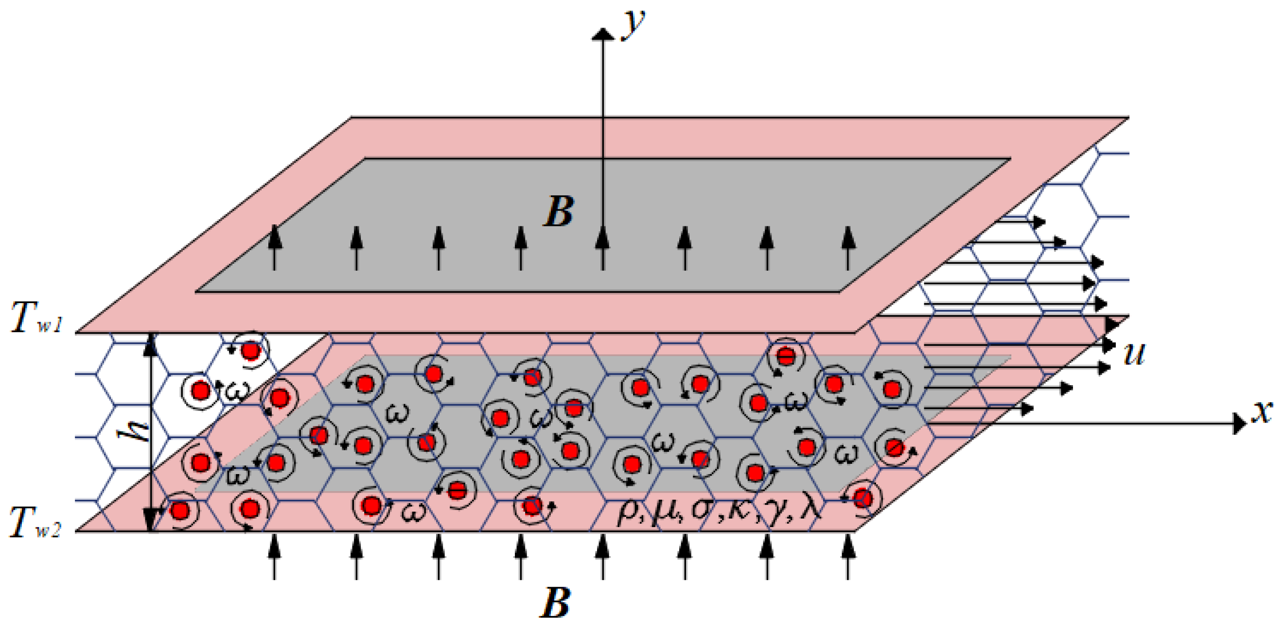
The physical model of the considered problem consists of two parallel and fixed plates extending in the
and
directions, with constant and different temperatures
and
, while, between them, there is a micropolar fluid flow in a porous medium (
Figure 1). Steady fluid flow is a consequence of the constant pressure gradient along the
axis. Perpendicular to this fluid flow, in the direction of the
axis, an external magnetic field, of strength
, is applied. Flow analysis is usually performed assuming the constant fluid electrical conductivity and treating the problem as one-dimensional, i.e., a fully developed flow takes place in the
direction. The problem considered in the paper is given in the inductionless approximation and, due to a small difference in the temperature of the plates, buoyance force is neglected. Taking these approximations into consideration, the vectors of fluid velocity
and external magnetic field
are
The governing equations for the flow, under the above-stated assumptions, can now be written as
From the previous system of Equations (7)–(9), it can be noted that Equations (7) and (8) need to be solved together, i.e., as coupled equations.
Appropriate fluid and thermal boundary conditions for this problem are represented by expressions (10):
The no-slip conditions require that the fluid velocities are equal to the plate velocities, that the boundary temperature conditions are isothermal conditions and that there is no microrotation at the plates.
To solve the system of equations for the observed problem, it needs to be transformed into the non-dimensional form. Therefore, the following transformations are introduced:
The introduced non-dimensional parameters are well known in the theory of MHD micropolar fluid flow. The given parameters are —Hartmann number, —Prandtl number, —Eckert number, —coupling parameter, —spin gradient viscosity parameter, —porosity parameter (—porous medium permeability).
Equations (7)–(9), having been transformed into the non-dimensional form, have the following form:
The boundary dimensionless conditions for the previous equations are
As mentioned before, impulse Equation (12) and equation of angular impulse (13) are coupled. Therefore, after some mathematical transformations and operations, the fourth-order differential equation for non-dimensional velocity is obtained:
In Equation (16), the newly introduced constants
and
, are defined as
where
Finding a solution for the fourth-order differential Equation (16) is not an easy task. In this case, there are three possible solutions, which depend on the roots of the characteristic equation.
An appropriate particular solution of Equation (16) is
Meanwhile, the characteristic equation of the homogeneous part of Equation (15) is given in the form of
or
The roots of characteristic Equation (20) are
The mathematical model applied in the paper provides the possibility of predicting the fluid behavior based on the root of the characteristic equation for velocity (16). The exact analytical solution, obtained in this way, enables the analysis of the influence of all significant parameters without the need to repeat the numerical solution of partial differential equations for each case. Furthermore, the solution can be used to check the numerical solution of some more complex partial differential equations.
The existence and uniqueness of the solution are analyzed when analyzing the roots of the characteristic equation of the partial differential Equation (16). Depending on the value of (it can be higher, lower or equal to zero), characteristic Equation (20), and therefore Equation (16), has three possible solutions.
For example, as expression depends on the physical properties of the fluid ( the strength of the external magnetic field , the permeability of the porous media and the distance between the plates , for different values of these variables, expression can be positive, negative or equal to zero.
Let us consider a problem of certain fluid flow in porous media between plates [
36]. The physical properties of the fluid are
where the strength of the external magnetic field is
, the porous media permeability is
and the distance between the plates is
. For the set values, the numerical value of expression
becomes
However, if we change the strength of the external magnetic field from
to
, the value of expression
becomes
or, for the value of ,
Based on the previous discussion, three possible solutions for non-dimensional velocity are given in the following equations:
- -
in the case
,
- -
in the case
,
- -
in the case
,
Now, three possible solutions for microrotation are given, respectively:
as well as for non-dimensional temperatures:
Together with the expressions for velocity, microrotation and temperature, the shear stress at the plates and the dimensionless heat transfer coefficient—the Nusselt number on the plates—are given as important characteristics of the flow and heat transfer.
It is very interesting to note that for a fluid in a microcontinuum (couple stress fluids, micropolar fluids, polar fluids, dipolar fluids, etc.), the stress tensor is not symmetric. The shear stress in the considered problem is defined by the following expression:
- -
in the case
,
- -
in the case
,
- -
in the case
,
As the Nusselt number represents the ratio of convective to conductive heat transfer at a boundary in a fluid, it is very important to understand heat transfer on the plates. Hence, the Nusselt number on the plates in the considered problem is
- -
in the case
,
- -
in the case
,
- -
in the case
,
3. Results and Discussion
In this section, the results for velocity, microrotation and temperature, as well as for shear stress and the Nusselt number, are presented graphically. The influence of the external magnetic field, the characteristics of the micropolar fluid and the characteristics of the porous medium are investigated and presented using the Hartmann number (), coupling () and spin gradient viscosity parameter (), as well as the porosity parameter (). Throughout this investigation and based on the obtained results, some basic conclusions on the flow of a micropolar fluid in porous media can be made. The values of the dimensionless parameters were chosen in such a way that the graphs would show the tendency of changes in physical quantities, with the change in the values of the given parameters.
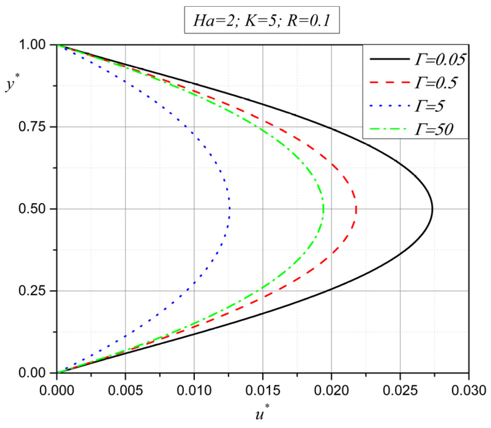
The first three figures show the influence of the additional viscosity gamma (), through the spin viscosity parameter (expressions 11), on velocity, microrotation and temperature.
From
Figure 2, it can be noted that the velocity decreases with an increase in the spin viscosity parameter
from the value of
to
. However, at the same time, with a further increase in the spin gradient viscosity parameter (
), the velocity starts to increase. This means that the velocity function has reached its extreme for a value of the spin viscosity parameter between
and
.
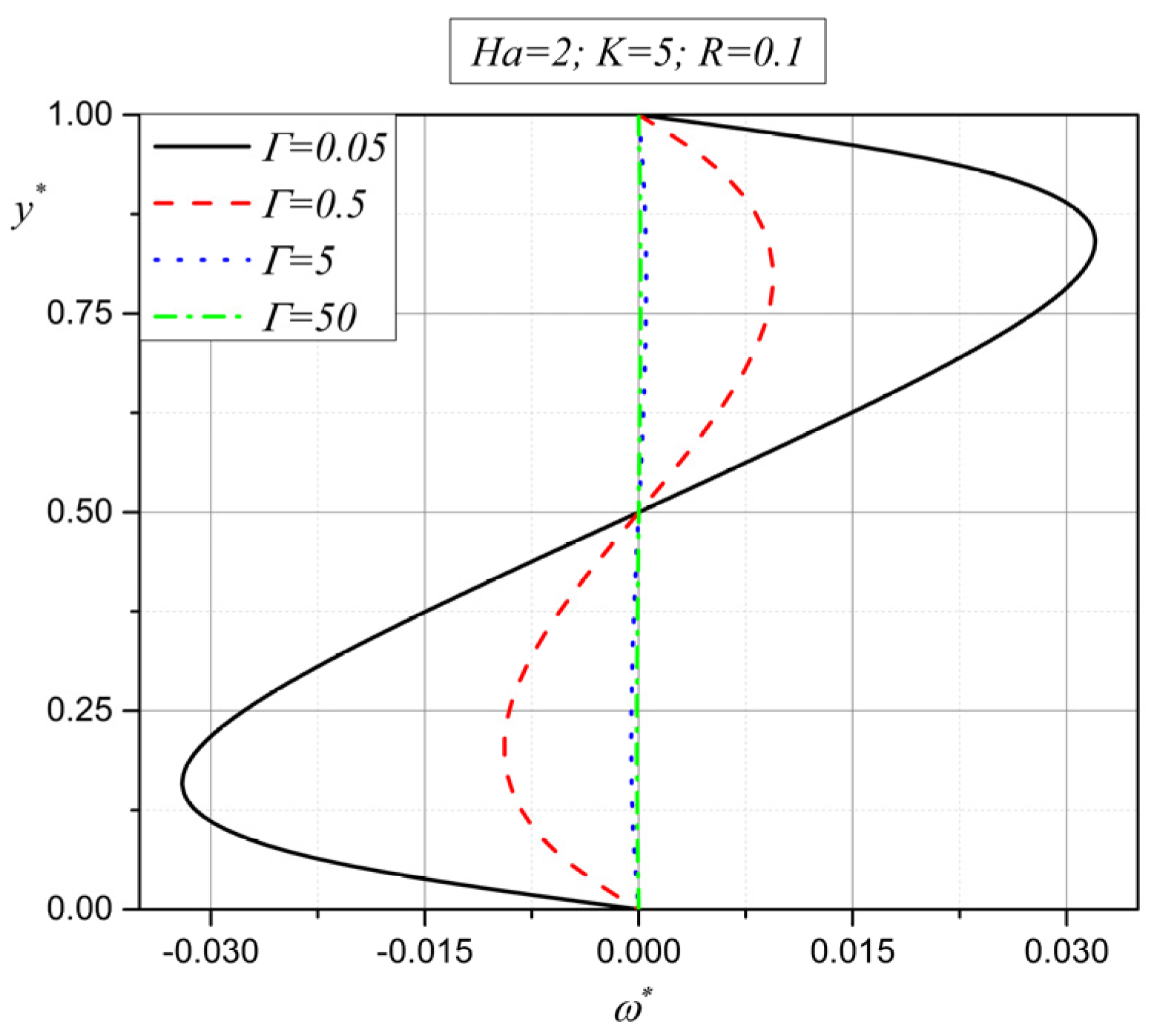
Figure 3, which represents the influence of the spin viscosity parameter
on the vector of microrotation, shows that a decrease in the absolute value of microrotation occurs in the entire height of the channel with an increase in the spin viscosity parameter
. Both figures show that with an increase in the additional viscosity gamma (
), the motion characteristics of the micropolar fluid start to decrease. This is the expected phenomenon of the viscous braking of the fluid flow, which is a consequence of the increase in the total viscosity of the fluid.
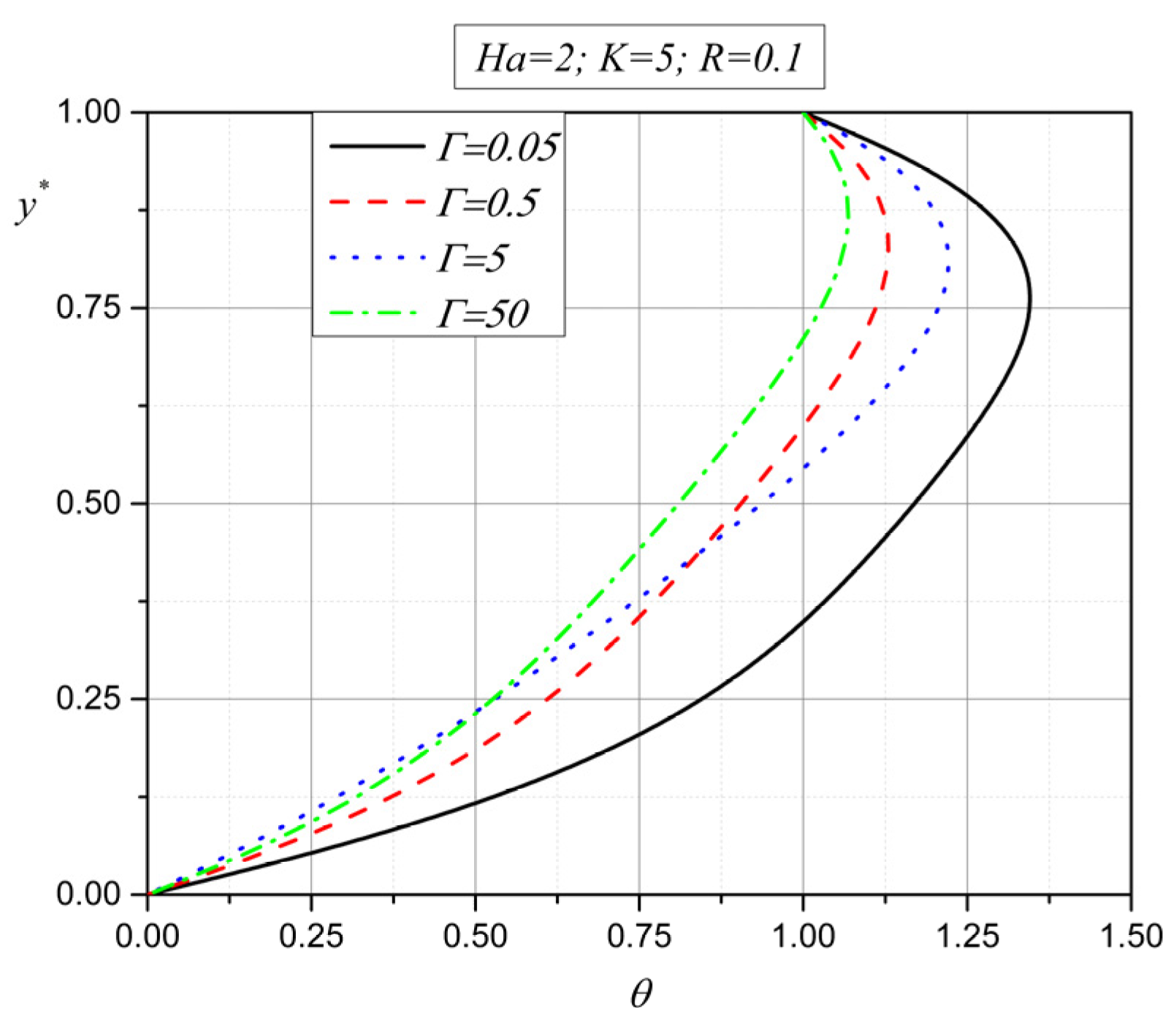
An increase in the additional viscosity gamma (
) leads to a decrease in temperature in the middle of the channel (
Figure 4). As a consequence of a decrease in velocity and microrotation with an increase in the spin gradient viscosity parameter
, Joule heating in the middle of the channel decreases. An increase in temperature near the plates, on the other hand, happens due to the viscous heat.
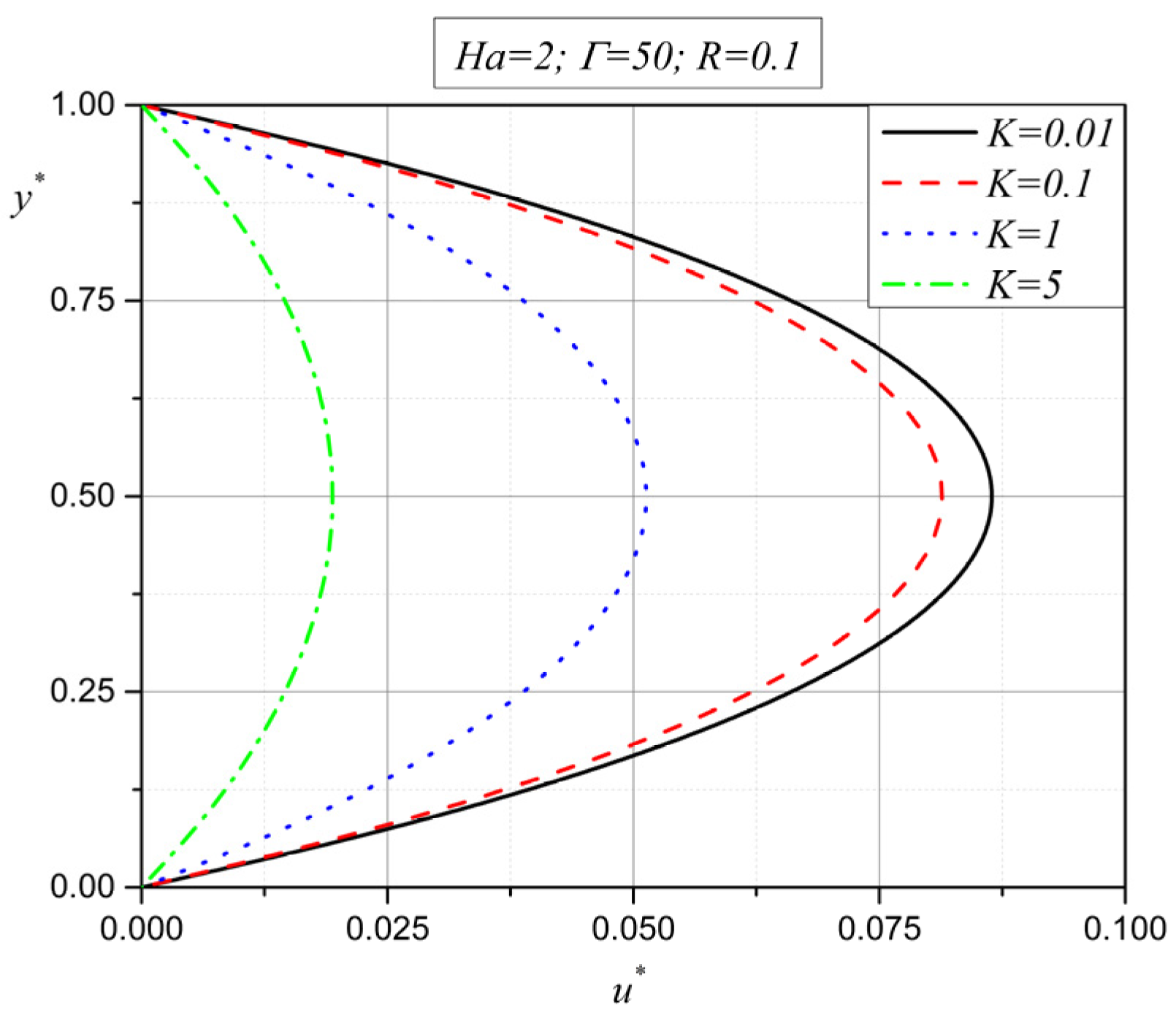
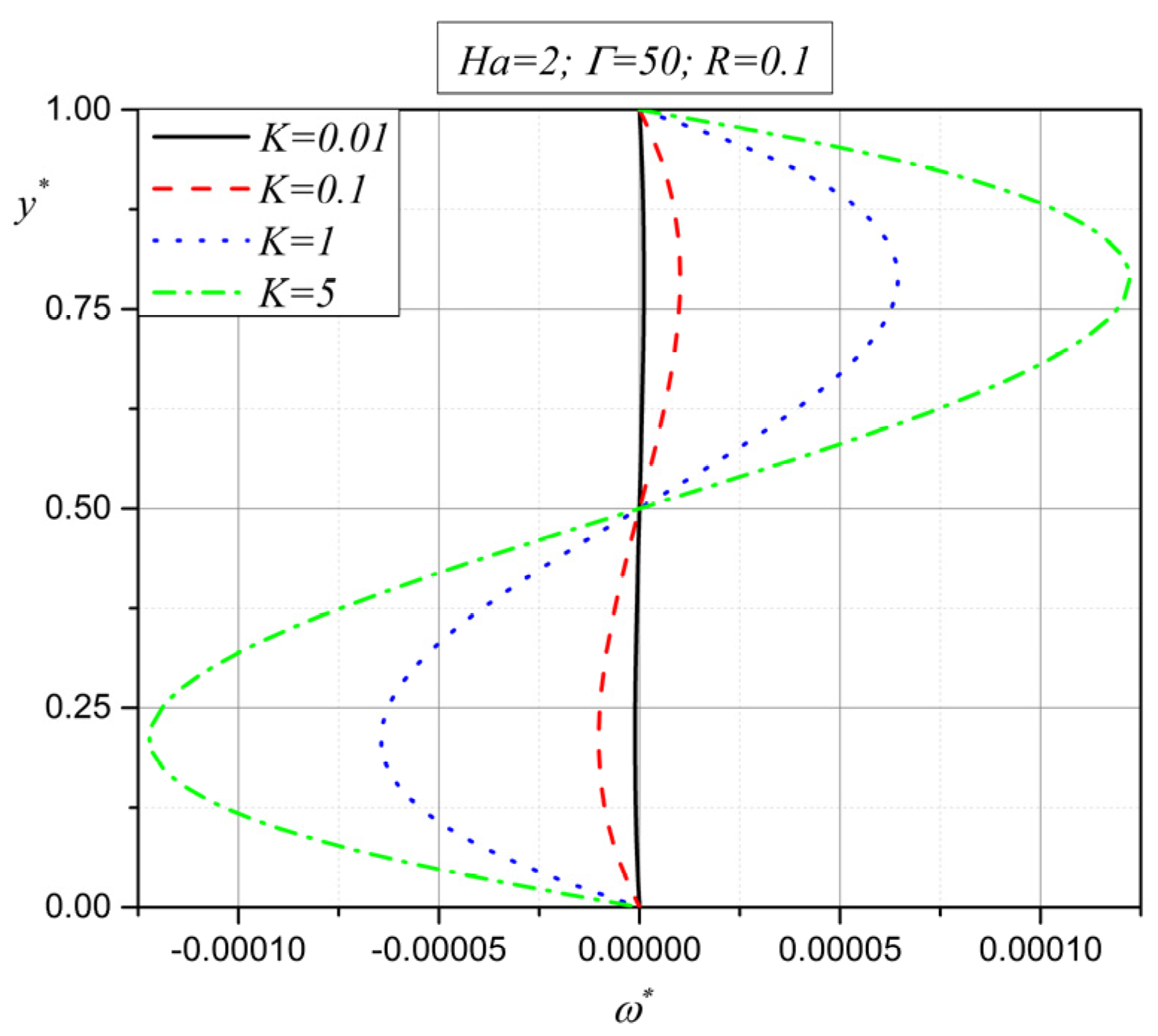
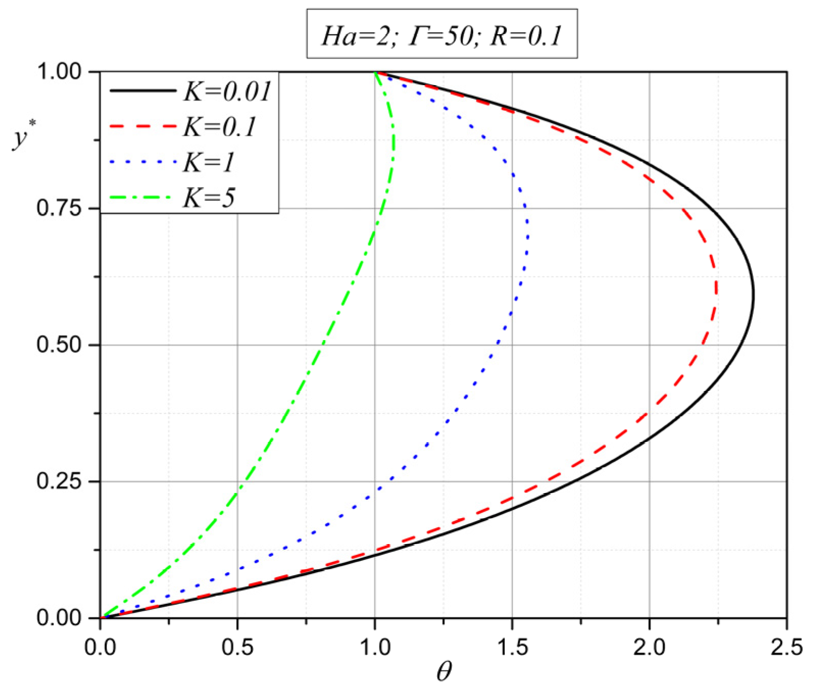
Together with the additional viscosity gamma (), one more viscosity is taken into consideration when micropolar fluids are investigated. The influence of the additional viscosity lambda () is presented through the coupling parameter . The next three figures show the velocity, microrotation and temperature dependency on the coupling parameter .
From
Figure 5 and
Figure 6, it is obvious that the additional viscosity lambda emphasizes the characteristics of micropolar fluids [
39]. The vector of microrotation, defined with angular impulse Equation (13), is the landmark of micropolar fluids. Because of this, from
Figure 6, it can be noted that an increase in the coupling parameter
leads to an increase in the absolute value of microrotation.
Figure 5 shows that the velocity decreases with an increase in the coupling parameter
. This means that the additional viscosity lambda (
) emphasizes the microrotation vector of small particles embedded in the fluid.
Figure 7 shows the influence of the coupling parameter
on the dimensionless temperature. With an increase in the coupling parameter
, conduction becomes the dominant form of heat transfer. This is also the consequence of the velocity decrease with an increase in the additional viscosity lambda (
), which has already been explained in
Figure 5.
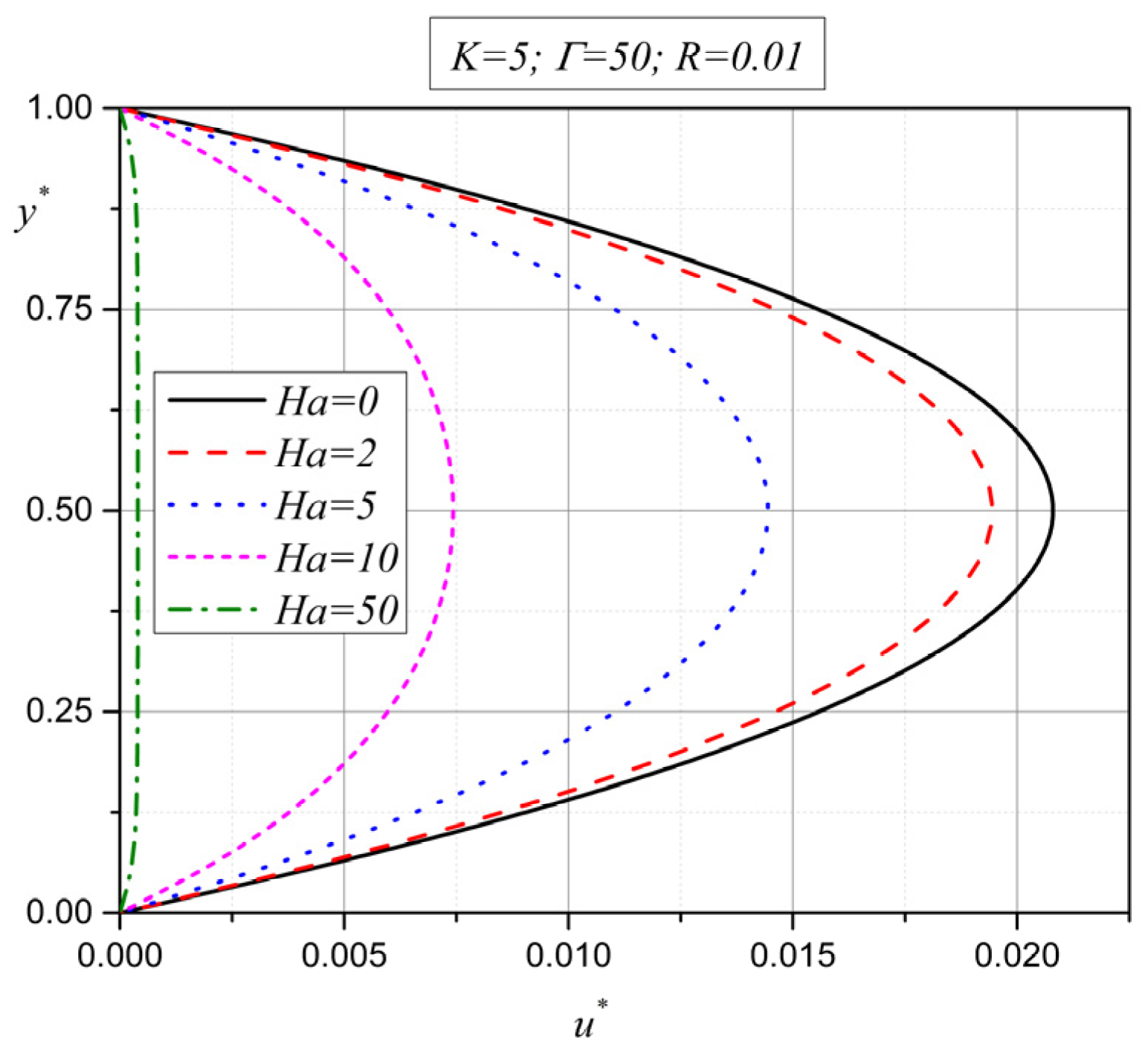
The next five graphs (from
Figure 8,
Figure 9,
Figure 10,
Figure 11 and
Figure 12) present the influence of the external magnetic field through the Hartmann number (
Ha) on velocity, microrotation, temperature, shear stress and the Nusselt number.
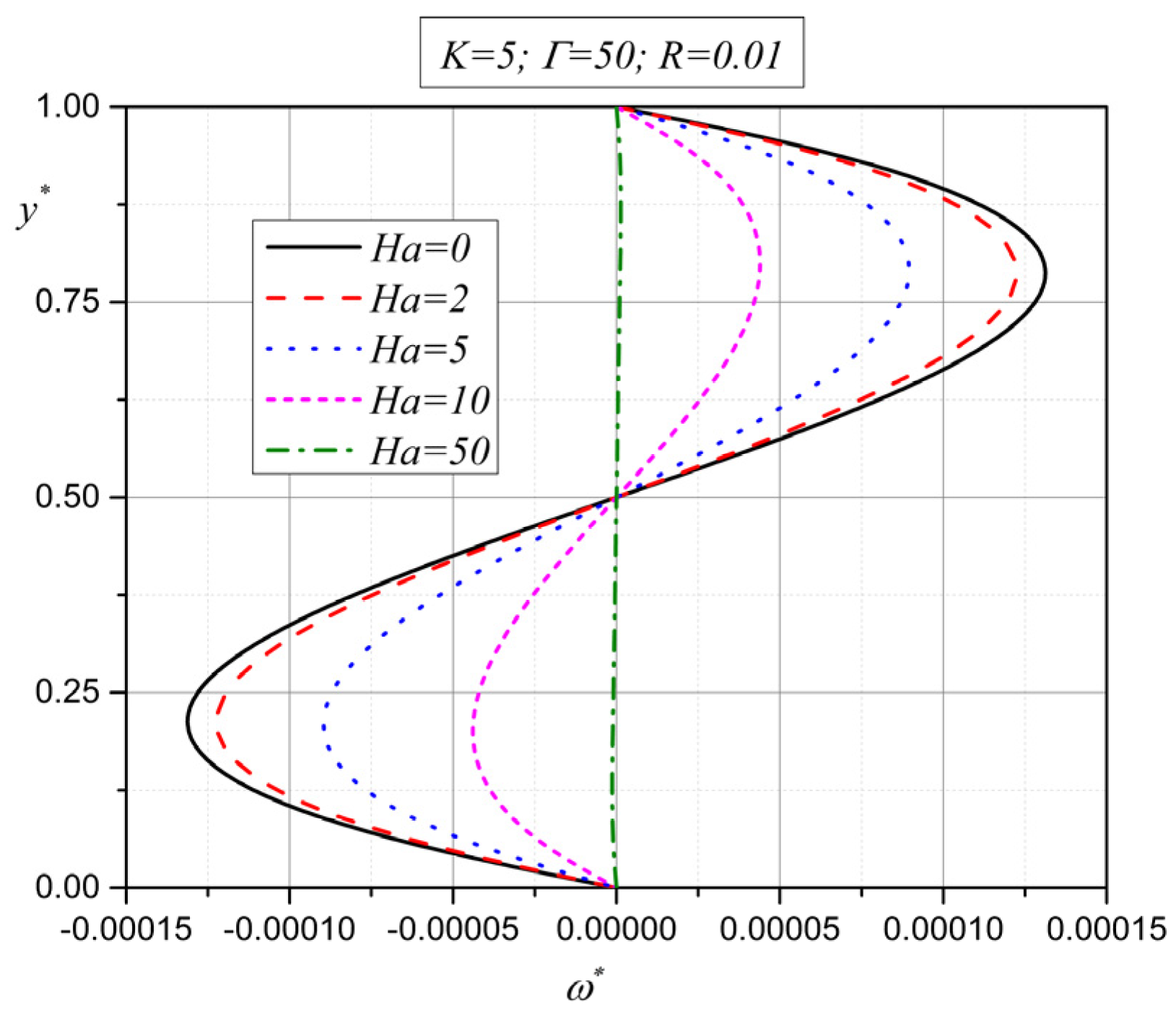
From
Figure 8 and
Figure 9, it is obvious that the velocity and microrotation decrease in absolute value as the Hartmann number increases [
40,
41]. This means that the motion characteristics of the micropolar fluid become lower in the entire width between the plates with an increase in the external magnetic field. This is something that is expected, as, with an increase in the external magnetic field in electrically conducting fluids, the Lorentz force acts in the direction opposite to the fluid flow and tends to retard the flow. It is very interesting to consider this through the roots of characteristic Equation (20), given by expression (21). In the previous section, it is determined that the value of expression
depends on the physical properties of the fluid (
the strength of the external magnetic field
, the permeability of the porous media
and the distance between the plates
. It is shown that with a change in the intensity of the external magnetic field
, there is a change in the value of expression
(it becomes positive, negative or equal to zero), which means that the tendency of the velocity or microrotation vector, for certain fluids, can be determined simply by knowing the change in the value of expression
.
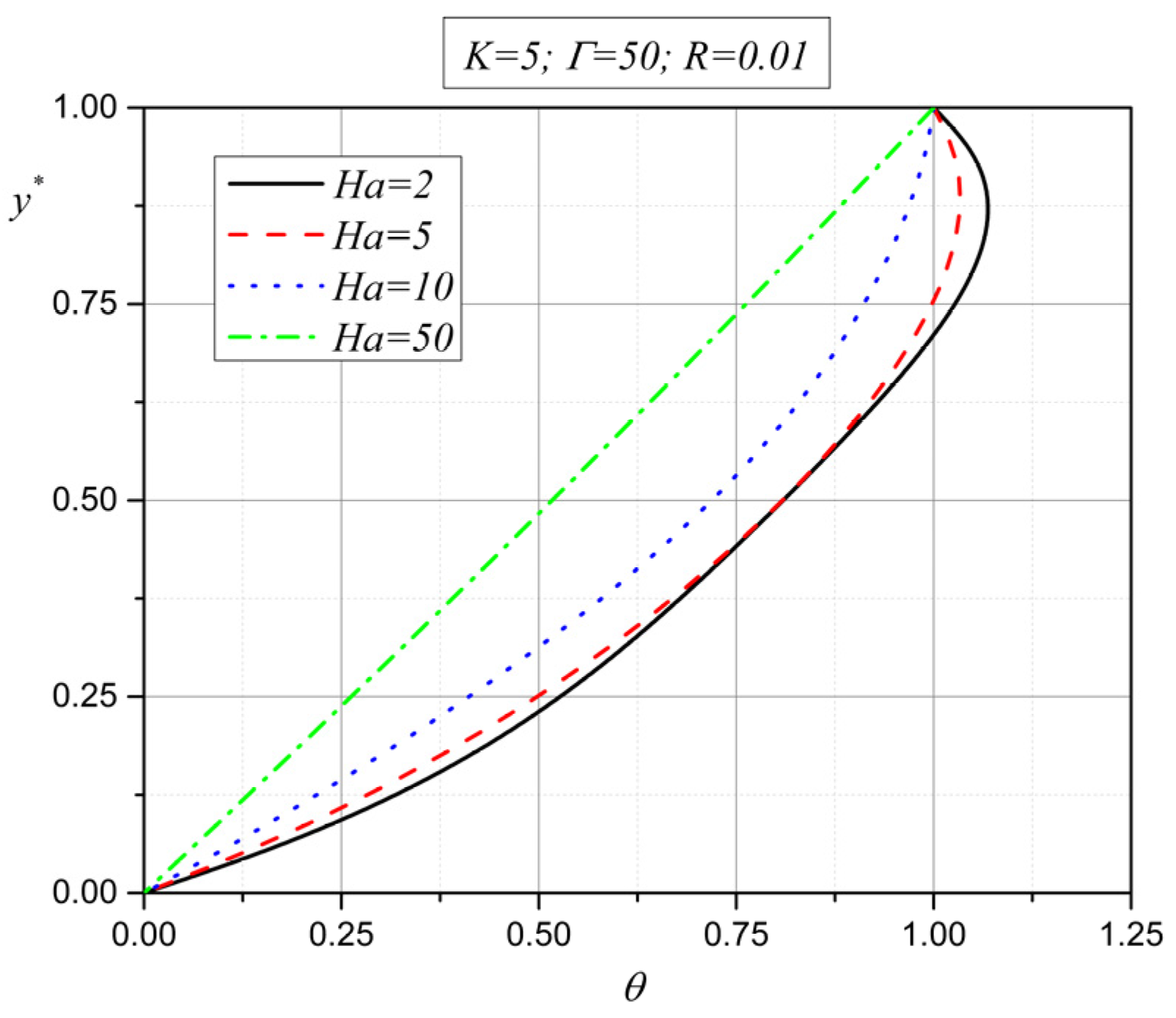
Figure 10 presents the influence of the external magnetic field on the dimensionless temperature. As the Hartmann number increases, conduction becomes the dominant form of heat transfer between the plates. For lower values of the Hartmann number, Joule heating increases the temperature of the fluid in the middle of the channel. The increase in temperature near the plates is the consequence of viscous heating.
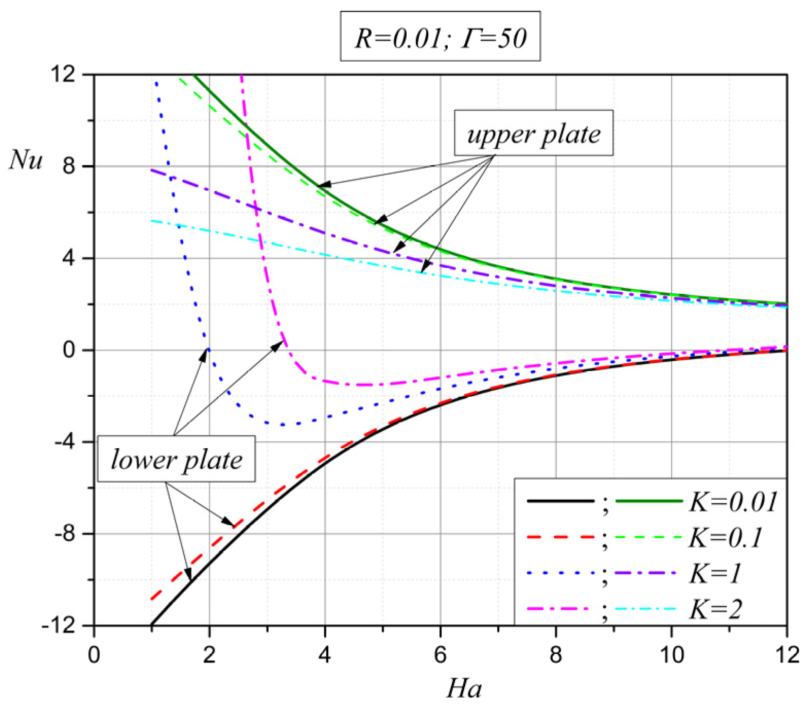
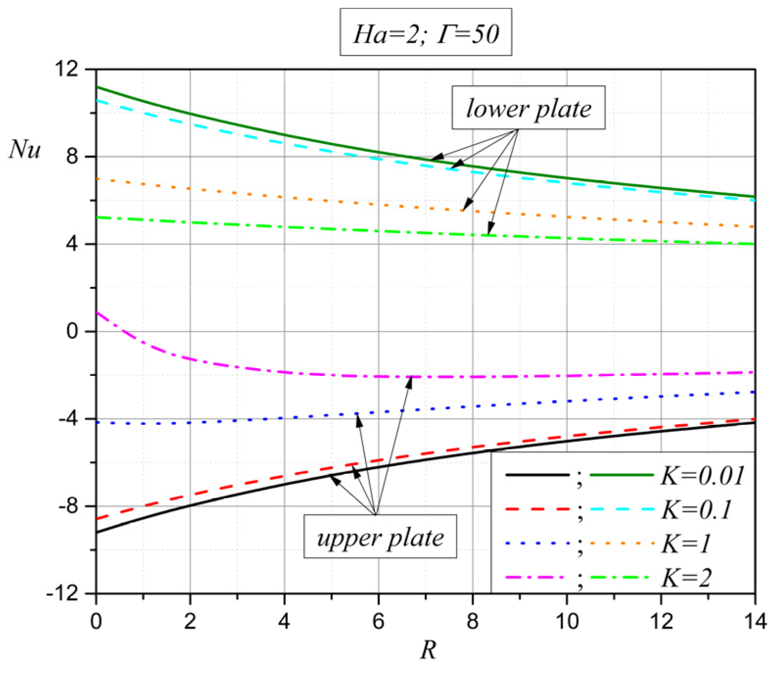
The next figure,
Figure 11, shows the behavior of the Nusselt number on the lower and upper plates for different values of the Hartmann number (
Ha) and coupling parameter (
K). For the lower as well as for the upper plate, the Nusselt number decreases in absolute value with an increase in the Hartmann number, which is expected in the case of the Hartmann flow, as heat transfer is mainly in the form of conduction. This is the consequence of the dominant influence of the magnetic field. On the other hand, for larger values of the coupling parameter (
K), heat transfer on the plates is lower, and this is due to an increase in the additional viscosity lambda (
), which is characteristic for micropolar fluids.
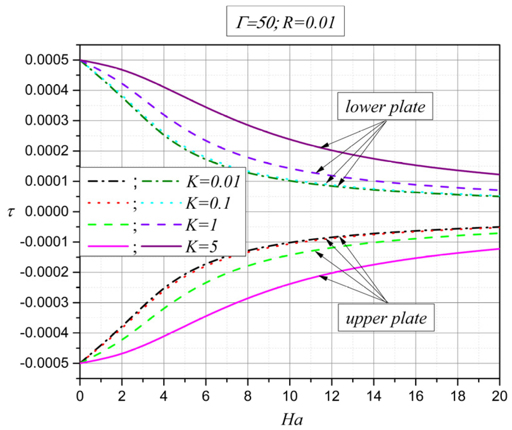
The influence of the external magnetic field and additional viscosity lambda on shear stress is presented in
Figure 12 [
42]. The increase in the Hartmann number causes a decrease in shear stress in absolute value, both on the lower and the upper plates. As expected, for higher values of the Hartmann number, the Lorentz force decreases the velocity in the entire width of the channel (
Figure 8), and because of this, the shear stress becomes lower on the plates. In the other case, with an increase in the additional viscosity lambda (
), which implies an increase in the coupling parameter (
K), based on expressions (11), shear stress increases as the total viscosity of the fluid increases (the interpretation based on Equation (31)).
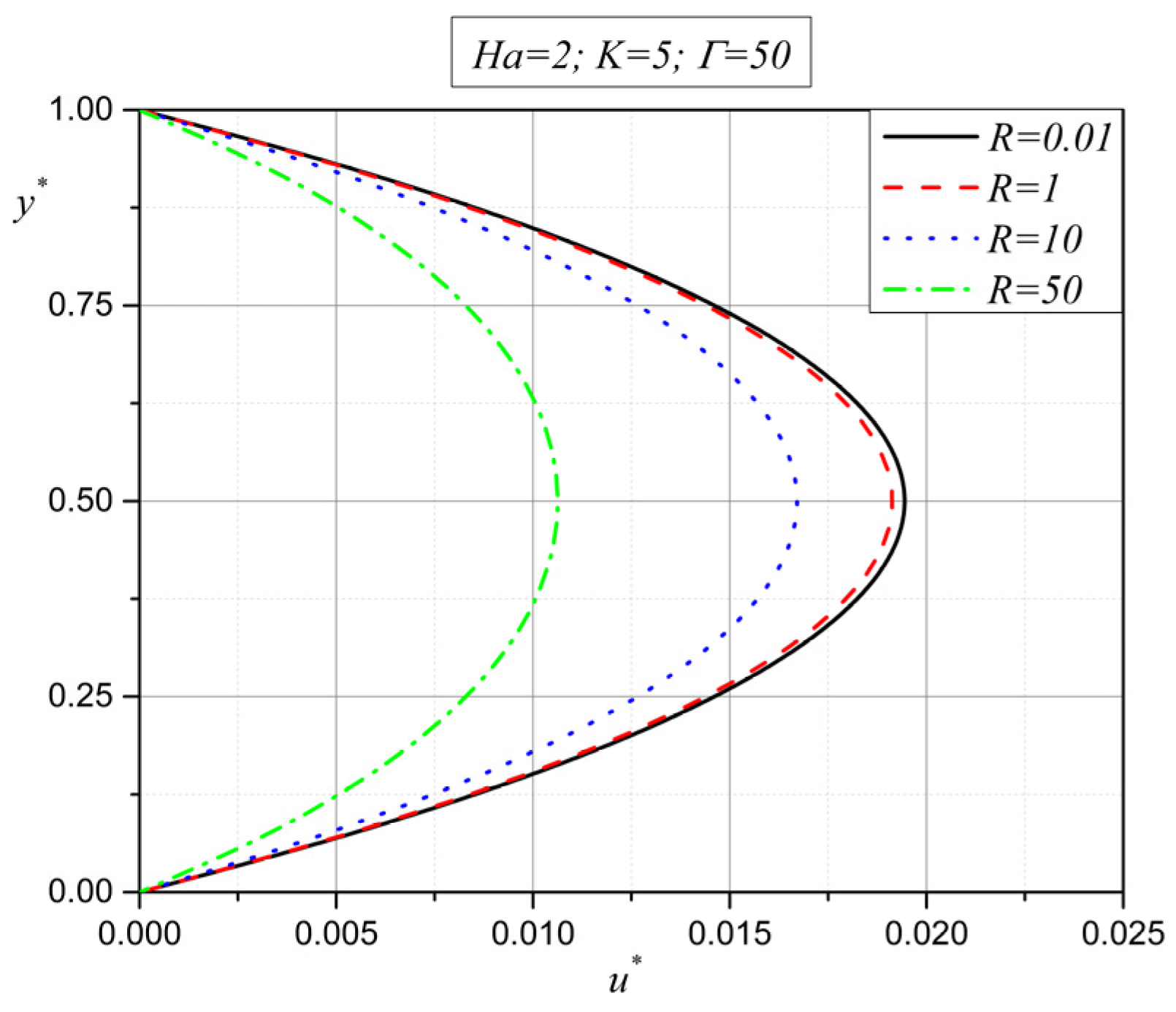
Finally, the last group of figures display the influence of the porosity parameter
on micropolar fluid flow and heat transfer. It is well known that as the value of the porosity parameter increases, the holes of the porous medium become smaller. The first two figures,
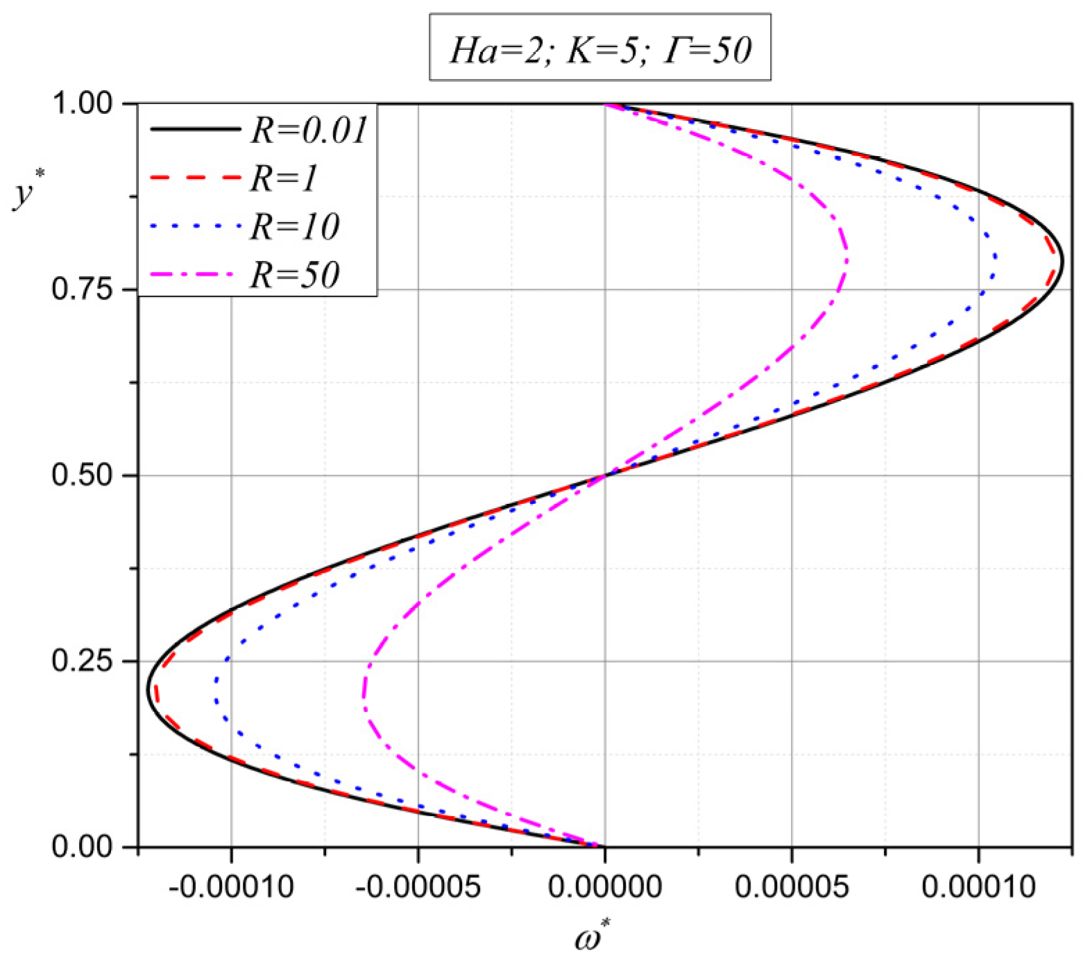
Figure 13 and
Figure 14, show the influence of the porosity parameter on the motion characteristics of the micropolar fluid, i.e., on the velocity and microrotation vectors.
As already mentioned, with an increase in the porosity parameter
, the fluid flow space becomes smaller so the micropolar fluid flow starts to decelerate; see
Figure 13. Velocity decreases with an increase in the porosity parameter
, and the microrotation vector decreases as well in absolute value in the entire height between the plates. This is something that is expected and has been shown by many authors [
43,
44]. This means that a physically smaller space causes the braking of the fluid flow in a porous medium.
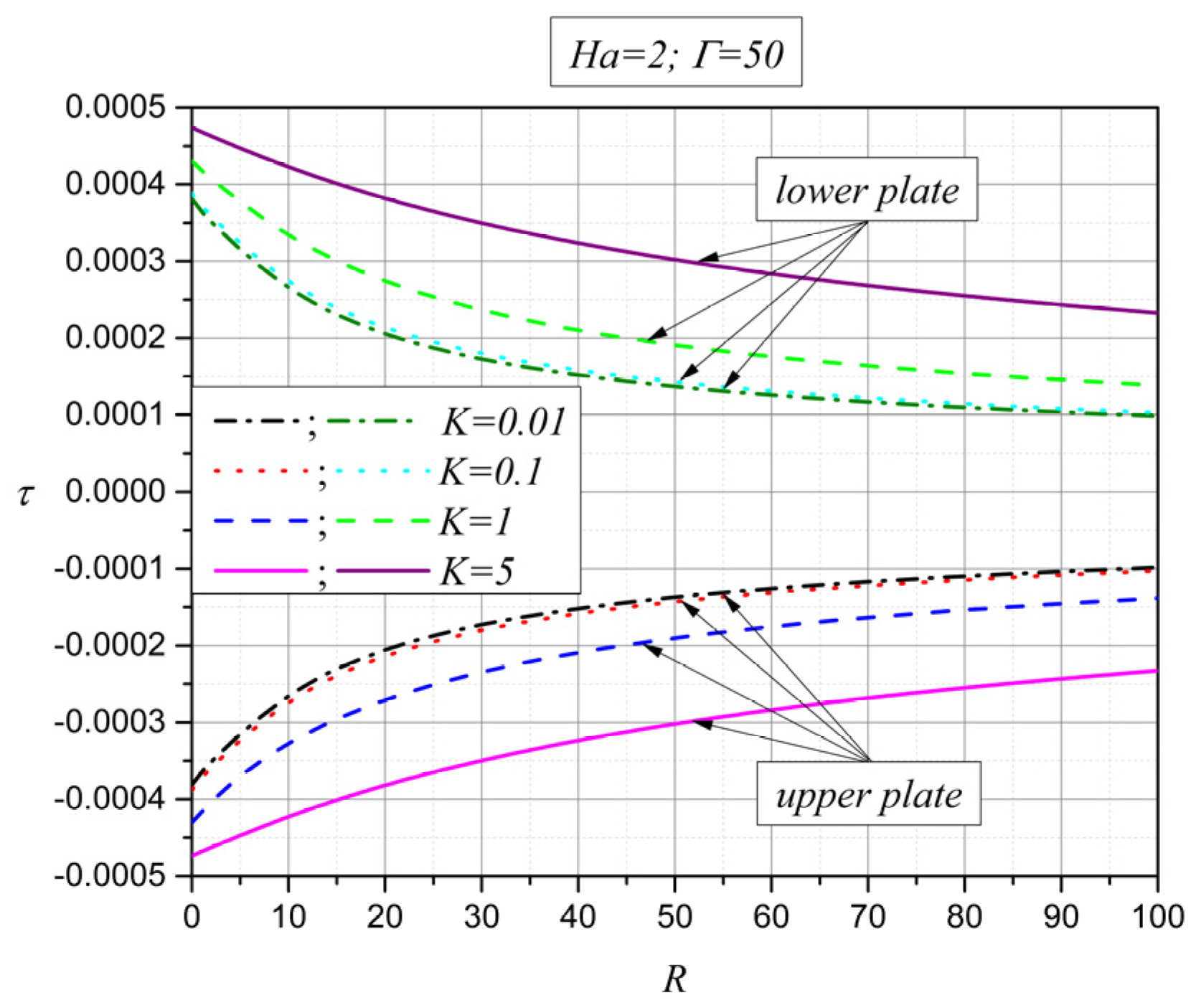
The next figure,
Figure 15, presents the influence of the porosity parameter
on the shear stress on the plates.
From
Figure 15, it is obvious that shear stress, both on the lower and the upper plates, decreases in absolute value with an increase in the porosity parameter. As already shown in the previous two figures, with an increase in the porosity parameter, the micropolar fluid flow decelerates, which leads to a decrease in shear stress on the plates. On the other hand, with an increase in the coupling parameter
, shear stress on the plates increases in absolute value on both plates. An increase in the coupling parameter
means that the additional viscosity lambda (
) is increasing, and further that the total viscosity of the micropolar fluid becomes higher. Because of this, and according to expression (31), shear stress on the plates increases with an increase in the coupling parameter
. This is due to the friction of the fluid against the plates with an increase in the overall viscosity of the fluid.
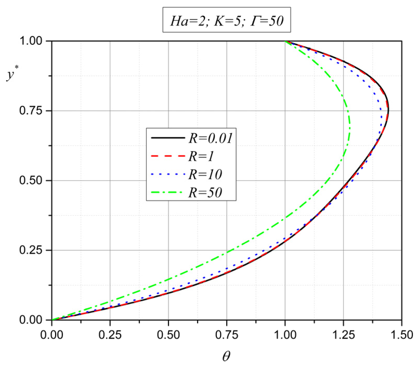
The last two figures,
Figure 16 and
Figure 17, provide answers to the influence of the porosity parameter on heat transfer.
From
Figure 16, it can be noted that for smaller values of the porosity parameter
, viscous heating increases the temperature near the plates, while Joule heating increases it in the middle of the channel. However, for larger values of the porosity parameter (
), Joule heating in the middle of the channel becomes dominant, as viscous heating near the plates starts to decrease.
The same can be seen in
Figure 17, where, with an increase in the porosity parameter
, heat transfer on the plates decreases in absolute value, both on the upper and the lower plates. Regarding the influence of the coupling parameter
, with an increase in this parameter, heat transfer on the plates becomes smaller as the total viscosity of the micropolar fluid increases.


