Article

Flow Boiling Heat Transfer Performance and Boiling Phenomena on Various Straight Fin Configurations

Department of Mechanical and Industrial Engineering, Faculty of Engineering, Gadjah Mada University, Jl. Grafika No. 2 Kampus UGM, Yogyakarta 55281, Indonesia
*
Author to whom correspondence should be addressed.
Fluids 2023, 8(3), 102; https://doi.org/10.3390/fluids8030102
Submission received: 11 February 2023 / Revised: 13 March 2023 / Accepted: 15 March 2023 / Published: 20 March 2023
(This article belongs to the Topic Applied Heat Transfer)

Abstract

:
The trend of miniaturisation in recent decades has led to the development of compact electronic devices. The reduction in the required dimension leads to the exponential rise in the heat flux dissipated from such a system. A proper thermal management system is necessary to keep the temperature of a computer chip’s junction within acceptable limits and maintain its performance. Flow boiling modification using straight fins in microchannels has proven to be an effective passive enhancement of the cooling system. The core interest of this research is figuring out the optimal configuration of the fin shapes and configurations. Hence, it is crucial to gain a comprehensive understanding of the flow boiling phenomenon to establish a more general approach. In this study, the boiling heat transfer performance of fin microchannels with various shapes and dimensions is investigated experimentally. The study has shown that the choice of fin geometry has a significant impact on the thermal performance of a heat transfer system. Specifically, the results indicate that a rectangular cross-section fin performs better than a trapezoidal one with the same fin gap. The rectangular cross-section fin exhibits the highest heat transfer coefficient of 5066.84 W/m2∙K, outperforming the trapezoidal fin in terms of heat transfer capability. As the hydraulic diameter reduces, the thermal boundary layer becomes denser, providing a more distributed saturated region. This leads to the increase in the heat transfer coefficient up to 22.5% and 17.1% for rectangular and trapezoidal fins, respectively. Additionally, the efficiency analysis shows that, albeit increasing the mass flux and reducing the gap increase the average cooling performance, but the pressure drop jumps up to 48%, reducing the efficiency of the heat removal system.

1. Introduction

Flow boiling heat transfer has been commonly applied in cooling technology. It provides high cooling capacity by relying on the latent heat transfer during the phase-change process. Additionally, as an active cooling system, flow boiling also relies on bubble dynamic enhancement due to fluid flow on the boiling surface, resulting in a higher cooling capacity than the passive pool boiling process. Currently, flow boiling achieves 10 times better cooling performance than single-phase systems [1]. Due to its nature of being a good-performing cooling technology, flow boiling is employed in most high heat flux applications, for instance, electronic cooling [2], nuclear power plants [3], and transportation [4].
In electronic cooling, for example, boiling heat transfer has been relied on since 1980 when the heat flux exceeds 100 W/cm2, exceeding the single-phase capability [5]. This growth in cooling demand has been led by the miniaturisation and increase in computer power, resulting in the rapid growth of heat flux released from computer chip [6]. However, although the current cooling capacity of flow boiling is within the remit of industrial requirements, future heat generation in the computer system will exceed the capability of current two-phase cooling technology. Hence, to fulfil that demand, boiling heat transfer enhancement remains the core interest of the research in cooling technology.
In flow boiling, many attempts have been made to increase the heat transfer coefficient of a small-scale system. The enhancements are either active or passive methods. In active enhancement, external energy is added to the system to increase the boiling heat transfer, such as surface electro-wetting [7] and vibration [8]. Meanwhile, passive enhancement relies on the modification of the pre-installed components of the cooling system, for instance, nano-fluids [9], surface nano-structure modification [10,11,12] and modifying the surface by 3D printing or porous graphite [13,14].
Another passive enhancement method that is widely applied is the microchannel. This method offers a wide range of merits. It provides high heat transfer performance and a low temperature gradient in relatively small and compact heat sink sizes [15,16]. In boiling heat transfer, a microchannel is defined by Cheng et al. [17] as having a Bond number (Bo) < 0.05. This dimensionless number reflects the relative magnitudes of gravitational force and surface tension. As such, a low Bo signifies that the influence of gravity on the flow boiling characteristics can be considered negligible. In microchannels, flow boiling is very sensitive to instability [18]; hence, comprehensive studies were conducted in each proposed modification.
Several studies have been conducted by employing microchannels for flow boiling enhancement. Ma et al. [18] investigated the effect of flow velocity and liquid subcooling on a square micropinned fin surface. It was proven that higher velocity leads to better cooling capacity in terms of the boiling curve and critical heat flux (CHF). Additionally, the study showed that at a lower temperature, the heat flux was more sensitive to the increase in wall superheat, risking the system overheating due to high heat flux. The further enhancement of the micropinned fin surface was obtained by Law and Lee [19]. They proposed an oblique pin fin array, whereby the heat transfer performance and CHF increased by 520% and 180%, respectively. This massive enhancement was achieved due to the increase in bubble generation on this particular geometry, ensuring the flow stability by reducing the pressure fluctuation and temperature gradient. This phenomenon was then further explained by Prajapati et al. [20]. It was found that the oblique profile provides a higher active nucleation site density number as well as the disruption of the thermal boundary layer. Furthermore, other geometrical shapes of pinned fin surfaces were evaluated by Sun et al. [21]. They compared the heat transfer of several geometries: square, triangular, circular, and ellipse.
The effect of the microchannel dimension on the heat transfer performance was examined by Harirchian and Garimella [15]. The study examined the boiling phenomenon of the channels when the gap varied between 100 μm and 5850 μm by flow visualisation and temperature measurement. The results showed that at the smaller channel width, the bubble generation was restricted, hence the decreased heat transfer coefficient. A similar study was conducted by Deng et al. [8] who investigated the effect of the Dh of an Ω-shaped microchannel on the heat transfer performance. The study tested three microchannel variations with the Dh of 590 μm, 781 μm, and 858 μm. The study showed that the microchannel with the Dh of 781 μm provided a large heat transfer coefficient and a moderate pressure drop.
The numerical analysis of topological modification using a manifold microchannel heat sink (MMHS) was proposed by Zhou et al. [22]. In their study, the pressure drop was constrained as the varying parameter. It was found that the design with the highest pressure drop provided the highest heat transfer coefficient up to 87% compared to the lowest one. Another CFD simulation was conducted by Tian et al. [23] using a VOF two-fluid model. This study focused on mathematical modelling, whereby a new constant was found to obtain a validated flow model of the boiling process.
There is a wide range of surface modification alternatives that have been developed for flow boiling heat transfer. However, as its nature is an active cooling system, it requires external power for the pumping system to overcome the pressure drop. As the surface complexity increases, the pressure drop rises, leading to the requirement of high external power. One of the alternatives of surface modification with a relatively low pressure drop is the straight fin. Additionally, the manufacturability of this surface is simpler than the other types of finned heat sinks. A number of studies have been conducted in attempts to enhance heat transfer performance by surface modification. However, so far, only a few studies have been conducted on the implementation of a straight fin microchannel and its impact on power efficiency. These investigations are necessary to demonstrate the suitability of such an improvement when compared to other enhancement efforts.
This study aimed to investigate the flow boiling heat transfer performance and the phenomenon on straight fin microchannels. In this study, a set of experiments exploring the flow boiling performance of various straight fins with different shapes and dimensions was conducted. Furthermore, the ‘efficiency’ of the enhancement was investigated in terms of the heat transfer to pressure drop ratio. These results are expected to provide valuable insight into the flow boiling process in the microchannel as well as design guidelines for further enhancement and heat sink analysis.

2. Materials and Methods

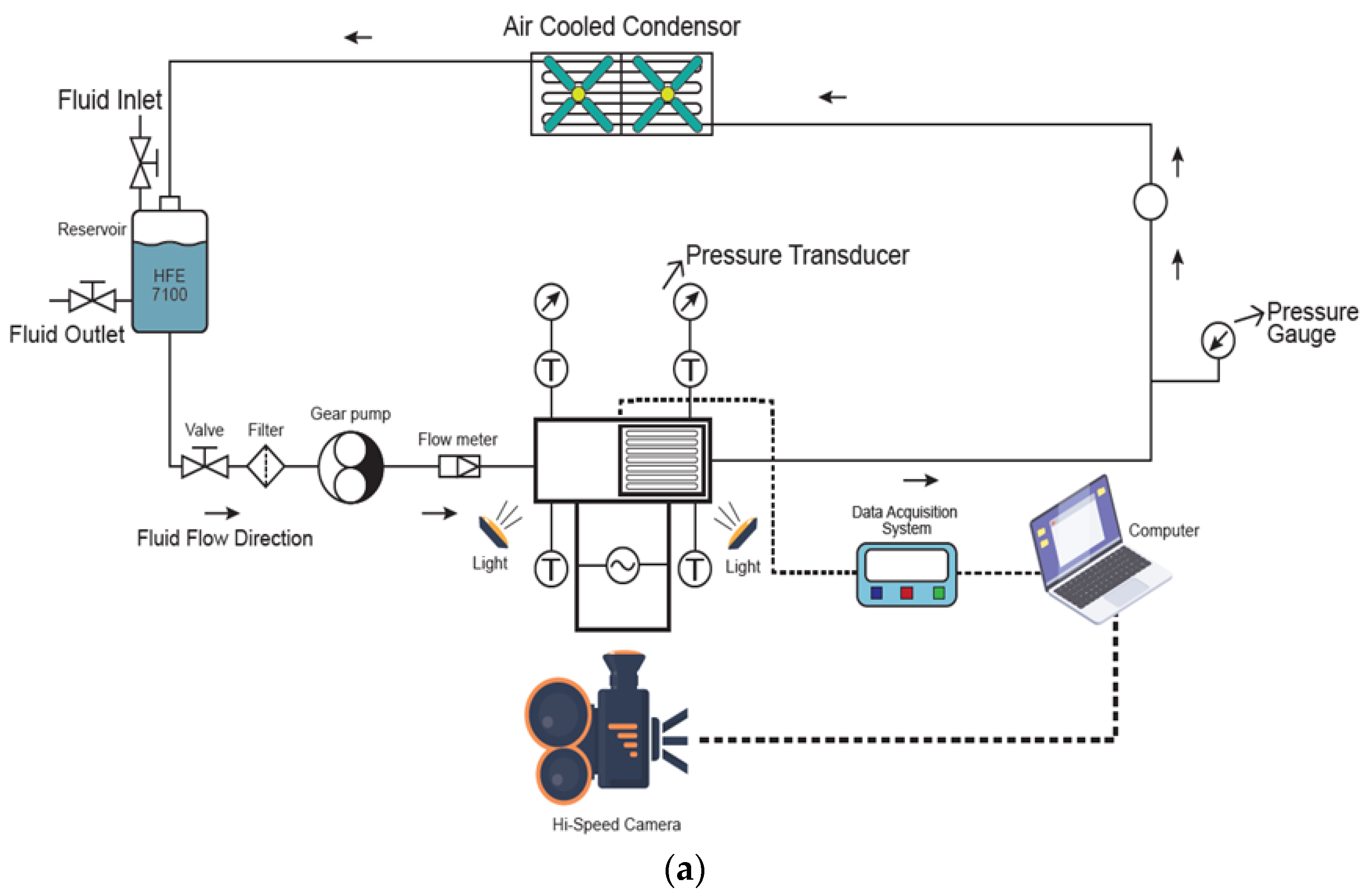
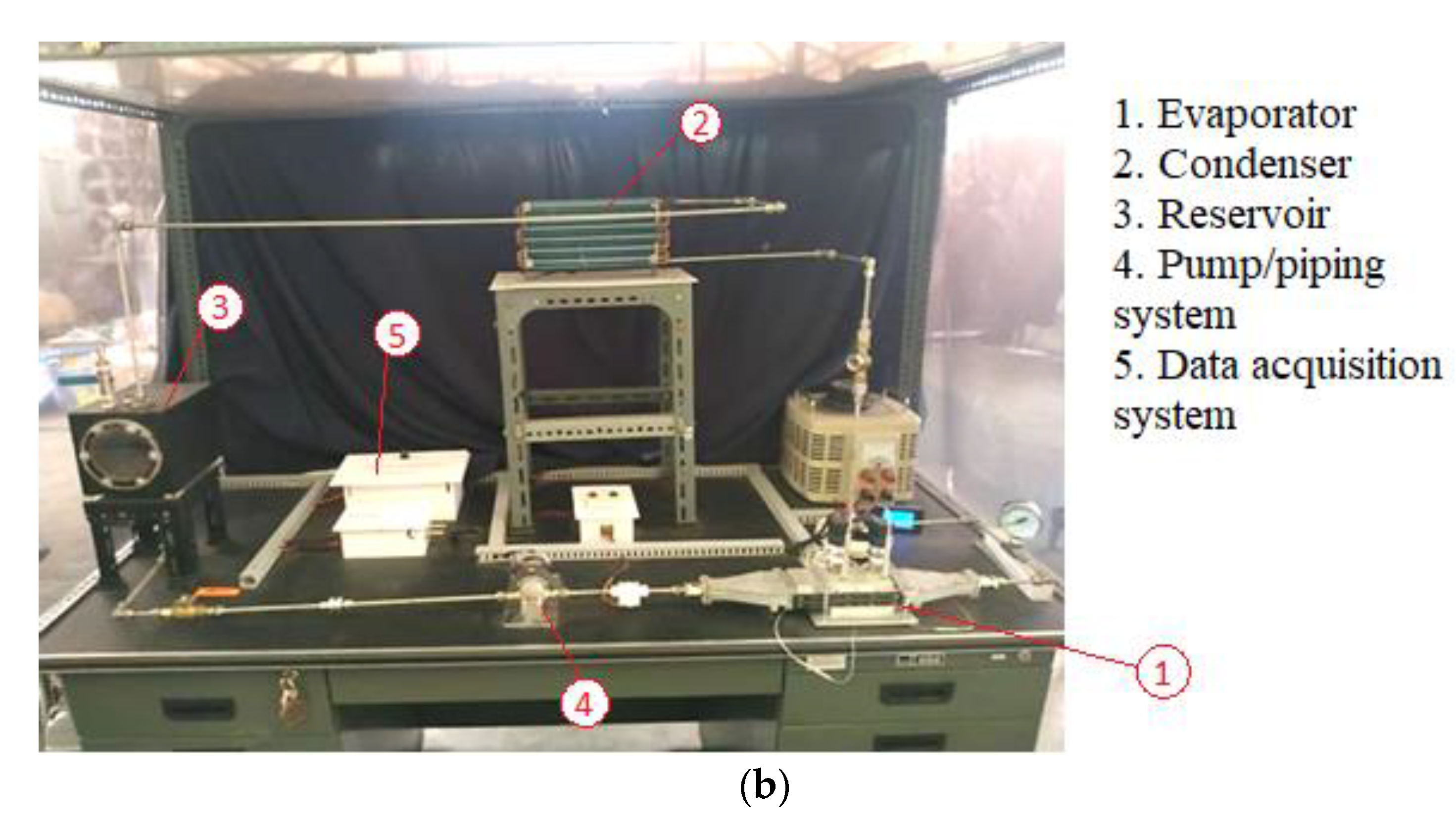
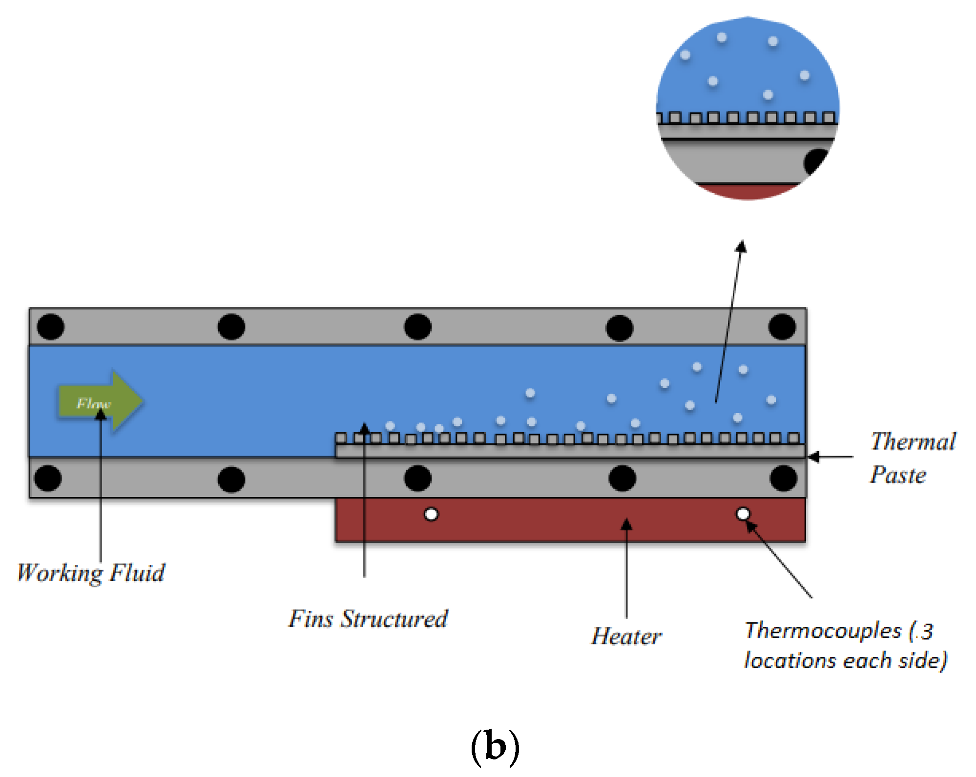
2.1. Experimental Facility
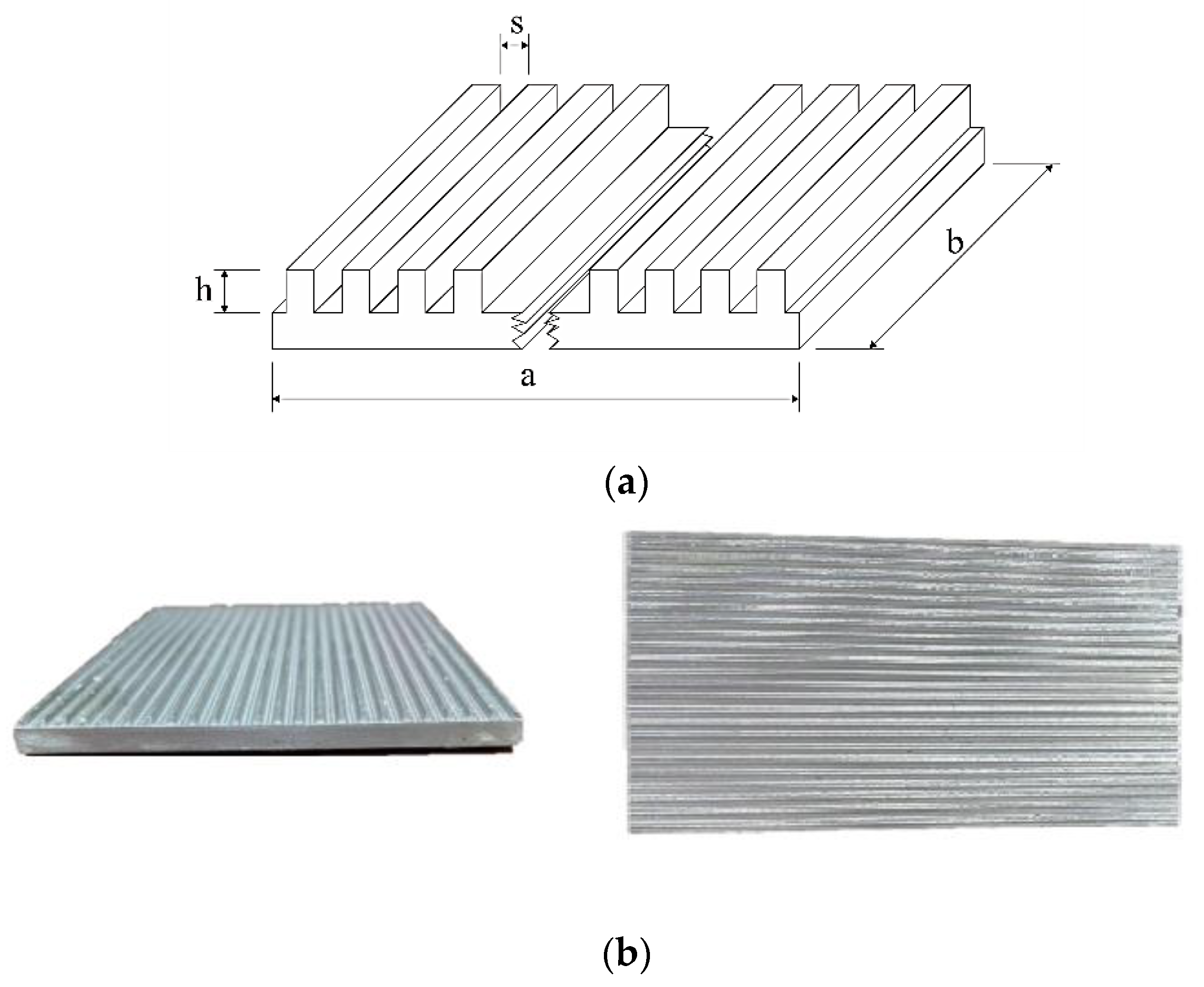
This study was conducted by conducting a set of experiments in a facility presented in Figure 1. The facility comprised several key components, including an evaporator, condenser, reservoir, pump, piping system and data acquisition system. The experiment was performed by pumping the working fluid through the evaporator with a controlled gear pump. The test sample (microchannel) was placed inside the evaporator to represent the real heat flux in the industrial application. The boiling phenomenon was then captured by a set of sensors and a camera for visualisation.
The evaporator, where the test sample was attached, consisted of some main parts, as shown in Figure 2. It had total dimensions of 474 mm (le) × 4 mm (we) × 48 mm (he) and channel dimensions of 60 mm (wc) × 18 mm (hc). To mimic the heat flux from the industrial application, total power of 2100 W was installed under the heating block. The supplied heat was controlled by a voltage regulator and monitored by a watt meter. Six k-type thermocouples were attached close to the surface of the heating block to estimate surface temperature. Meanwhile, two other k-type thermocouples used to measure fluid temperature were attached to the top of the channel. Furthermore, two pressure transducers were placed close to the inlet and outlet of the channel to measure the pressure drop caused by the system. Additionally, a transparent window was installed to observe and visualise the bubble dynamics during the experiment.
To ensure a steady state, an air-cooled condenser was placed after the evaporator. This component was responsible for releasing the absorbed heat from the working fluid, allowing the fluid temperature to go back to room temperature before entering the reservoir. The whole flow process was controlled by a pump controller and monitored by a flow meter with the sensor uncertainty of around ±2% accuracy and ±0.5% repeatability (full scale) to maintain the mass flux at the desired rate.

2.2. Test Samples

The test samples for this experiment were made of aluminium with a base thickness of 3 mm. In this study, two geometrical profiles were incorporated: rectangular and trapezoidal. For each shape, two test samples were fabricated with a variation in fin dimensions. In all test cases, the base dimension was kept at constant dimensions of 59 mm (a) × 81 mm (b). Meanwhile, the fin height and gap varied with the specifications presented in Figure 3 and Table 1.
This study employed HFE-7100, a dielectric fluid, as the coolant. This selection aimed to represent the real application of electronic cooling, whereby the implementation of dielectric fluid is desirable due to its compatibility with electronic cooling. This fluid has a low boiling point, allowing the system to boil under the maximum allowable temperature of the electronic system. Additionally, HFE-7100 has low dielectric strength, which restricts the short circuit when the device is immersed in the liquid. The properties of HFE-7100 are presented in Table 2.

2.3. Measurement and Data Acquisition

The experiments were carried out under sub-cooled boiling conditions, atmospheric pressure, and a room temperature of approximately 300 K. The power input was gradually increased from 100 W to 170 W in increments of 10 W. To ensure the system was in a steady state, data were recorded after 10 min and 20 iterations when the measured temperature fluctuation was negligible. The data were gathered using a National Instrument Data Acquisition System (DAQ) and displayed in LabView 2017 software. During the validation process, the pressure transducer’s recorded data were monitored to maintain a steady pressure, ensuring a constant rate of heat input from the heater and cooling from the condenser. Between each variation, the heater was turned off until the temperature was reduced to the initial temperature (room temperature) to remove the hysteresis of the sensors. Furthermore, the flow behaviour during boiling was captured with a macro-lens camera with a maximum frame rate of 1200 pixels and resolution of 1920 × 1080 pixels.
To estimate the surface temperature (Ts), the measured data from six thermocouples were incorporated. By employing the steady-state conduction equation, heat flux and calculated thermal resistance of the modified surface, the uniform surface temperature was estimated as follows:
T s = n T n n
This study considered two sources of data uncertainty: systematic and measurement uncertainties. The systematic uncertainty, caused by human errors during the experiment, was minimised by the strict procedures of the experiment. As a result, the repeatability of the measured sensor data was ensured, and it can be assumed that the systematic uncertainty was negligible. On the other hand, the measurement uncertainty was calculated by employing the sensor’s uncertainty specification, whereby the thermocouples and pressure transducer had the uncertainty/non-linearity of ±0.5 K and 0.25–0.5%, respectively. Furthermore, the uncertainties were quantified by using Taylor’s equation of uncertainty [27] as follows:
δ u u = δ m m 2 + δ n n 2 + + δ r r 2
where m, n, …, r are the independent parameter uncertainties which contribute to the final calculation, such as temperature, flow, and pressure measurement, where the standard deviation is calculated as follows:
σ m = 1 N i = 1 N m i m _ 2
here, m i and m _ are the sample values and the mean value of parameter v . Then, the uncertainty of δ m is given by:
δ m = σ m N
The uncertainty of the primary quantity of interest (hb) is estimated by employing Equation (2) to account for the combined effects of uncertain parameters, specifically q (3.3%), T s (1.5%), and T s a t (1.8%). Hence, the average uncertainty of hb is estimated at around 5.4%.

3. Results and Discussion

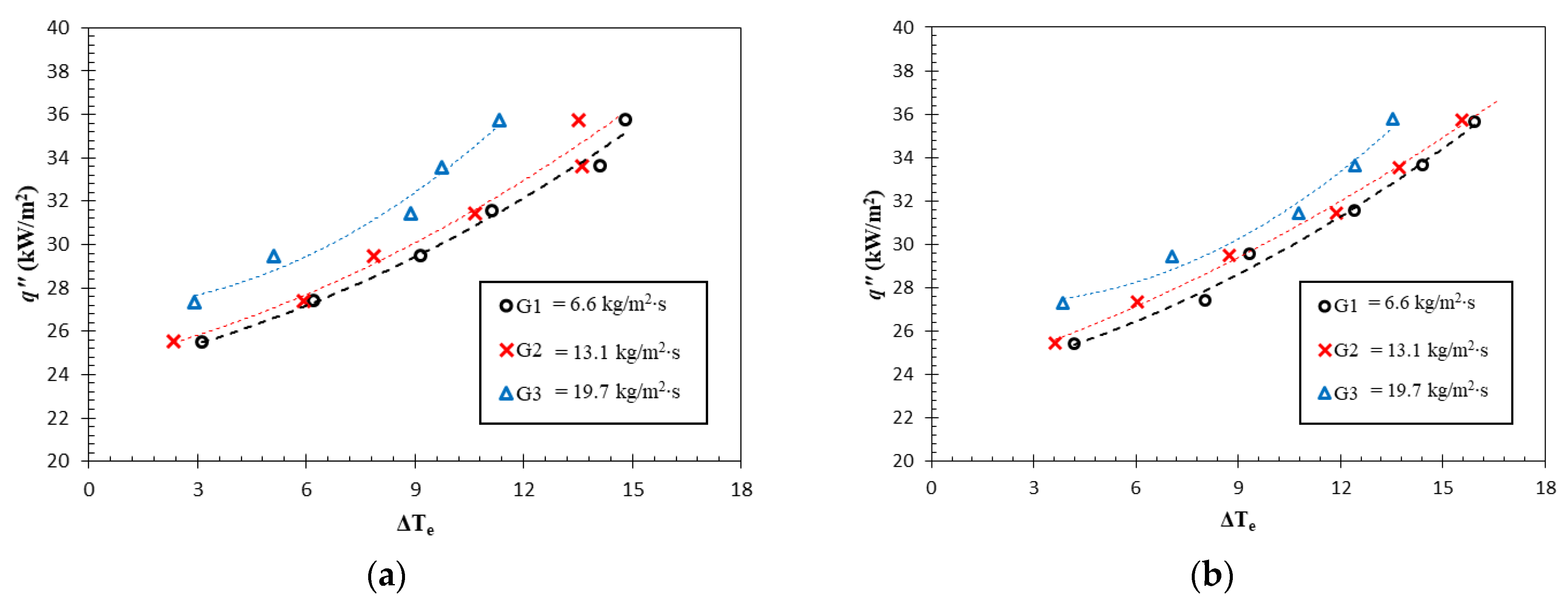
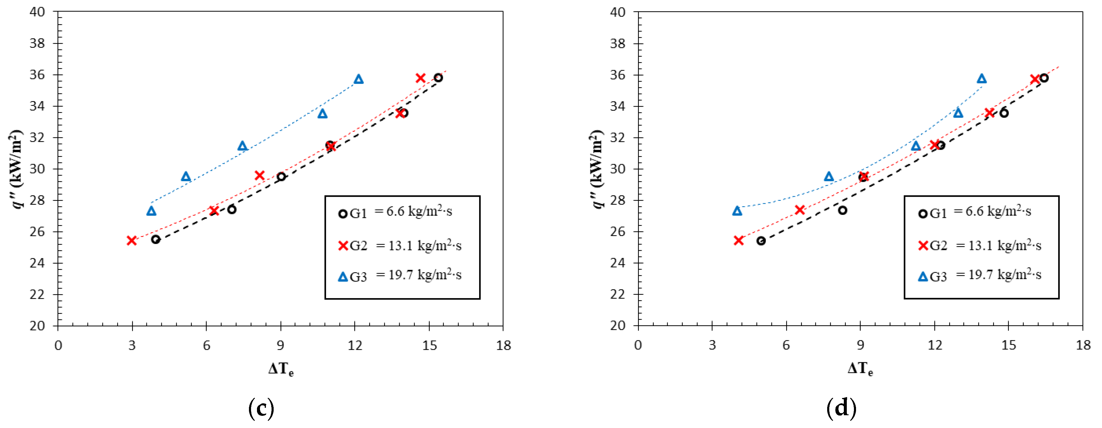
3.1. Boiling Curve and Cooling Performance

The results of this study are presented in the boiling curves presented in Figure 4a–d, which demonstrate the heat transfer efficiency by comparing the surface temperature at the given heat flux. A more pronounced curve indicates improved cooling performance by comparing the surface temperature at the given heat flux. In all results, the graphs become steeper as the heat flux rises, indicating better cooling performance. This can be attributed to an increase in more bubble generation, whereby the detached bubbles increased the contribution of the heat flux due to the bubble detachment and surface quenching phenomena [28].
The boiling curves depicted in Figure 4 showcase that the R1 test case exhibited the steepest curve and hence the lowest surface temperature at a specific heat flux. For the highest mass flux (G3), for instance, the Δ T e could be maintained below 12 K. Meanwhile, the remaining test cases at the identical working condition underwent an increase in surface temperature of 13.53 K, 12.12 K and 13.92 K for R1.5, T1 and T1.5, respectively. A similar trend was observed at the other mass fluxes. Albeit having relatively low discrepancy, this trend proves that the T1 test case provides the highest cooling capacity, allowing it to maintain the low surface temperature.
To further analyse the heat transfer performance, the cooling capacity was quantified by calculating the average heat transfer coefficient as follows:
h _ b = q n e t Δ T e = q n e t T s T s a t
where h _ b is the average boiling heat transfer coefficient, q n e t is the net heat flux applied to the channel, T s is the fin surface temperature, and T s a t is the saturation temperature of the working fluid. The result of this calculation is presented in Figure 5.
The boiling performance presented in Figure 5 confirms the findings discussed earlier, whereby the R1 test case provided the highest heat transfer coefficient (HTC), followed by T1, R1.5 and T1.5. The maximum HTC was obtained on the R1 test case at 5066.84 W/m2∙K. Upon comparing the average heat transfer of different mass flux variations, the HTC of the R1 test case was 31.19% higher than T1.5. Both rectangular and trapezoidal fins demonstrated the enhancement of the heat transfer coefficient as the fin gap reduced. This was the result of the higher total area (see Table 1), whereby the 1 mm gap test cases had 1.1% and 1.2% wider areas for rectangular and trapezoidal fins, respectively. This small area increase, however, accounted for a significant enhancement in the heat transfer coefficient by 22.5% for rectangular and 17.1% for trapezoidal fins.
Furthermore, in all surface variations, the findings illustrate a rise in HTC with an increase in mass flux. The heat transfer coefficient in the R1 test case, for instance, increased by 29.97% from the mass flux of 6.6 kg/m2∙s to 19.7 kg/m2∙s. This pattern was anticipated since flow boiling relies on fluid flow to enhance the cooling performance. As the fluid velocity increases, the bubble lifts off easier from the surface, avoiding the concentration of thermal resistance due to bubble crowding on the boiling surface [29].
An additional mechanism is responsible for this considerable enhancement. As mentioned earlier, boiling heat transfer relies on bubble generation on the surface. As the fin gap and Dh reduced, the thermal boundary layer within the vertical surface became closer. This resulted in a more saturated region across the flow cross-section. This led to more active nucleation sites and bubble generation across the boiling surface, which produced better boiling heat transfer performance. This mechanism is illustrated in Figure 6. This result supports the thermal boundary layer breakage concept proposed by Prajapati et al. [20]. The authors noted and depicted that certain fin designs result in an incomplete development of the thermal boundary layer, hindering the smooth flow of bubbles. Even though the low void fraction prevents the visual observation of this phenomenon, a similar mechanism can result in a uniformly distributed saturated region. The uneven distribution of the boundary layer causes a variation in heat transfer performance, as the Onset of the Nucleation Boiling (ONB) typically only occurs in the saturated region. However, this mechanism only occurs on the low void fraction and sub-cooled boiling regime, whereby the ONB is not yet observed in most locations.
In addition to ONB, Vacj et al. [30] demonstrated the impact of saturated boiling on heat transfer performance. They showed that at sub-cooled boiling conditions, distributed temperature reduction has a more significant effect on boiling compared to saturated boiling. The proposed mechanism is supported by this concept, as a narrow fin gap can create a more saturated region.
This mechanism also agrees with the result of the geometrical shape comparison. In the comparison between the R1.5 and T1 test cases, for instance, although the area of the R1.5 test case was higher than T1, the heat transfer coefficient was slightly lower due to the larger Dh. This means that even though the R1.5 test case had more contact area between the hot surface and working fluid, single-phase convection dominated the heat transfer process because a less saturated region was observed in the channel. Hence, the average heat transfer coefficient was lower. The summary of the average heat transfer coefficient in different Dh values is presented in Table 3. The results clearly show a strong correlation between the average heat transfer coefficient and Dh. As the Dh increases, the heat transfer coefficient declines. In the present analysis, the determination of hydraulic diameter was carried out by employing a comparison between the cross-sectional area, taken perpendicularly to the direction of flow (A), and the wetted perimeter (P), as expressed by Equation (6). Herein, A and P are precisely defined at the uppermost section of the fin, where the fluid comes into contact.
D h = 4 A P

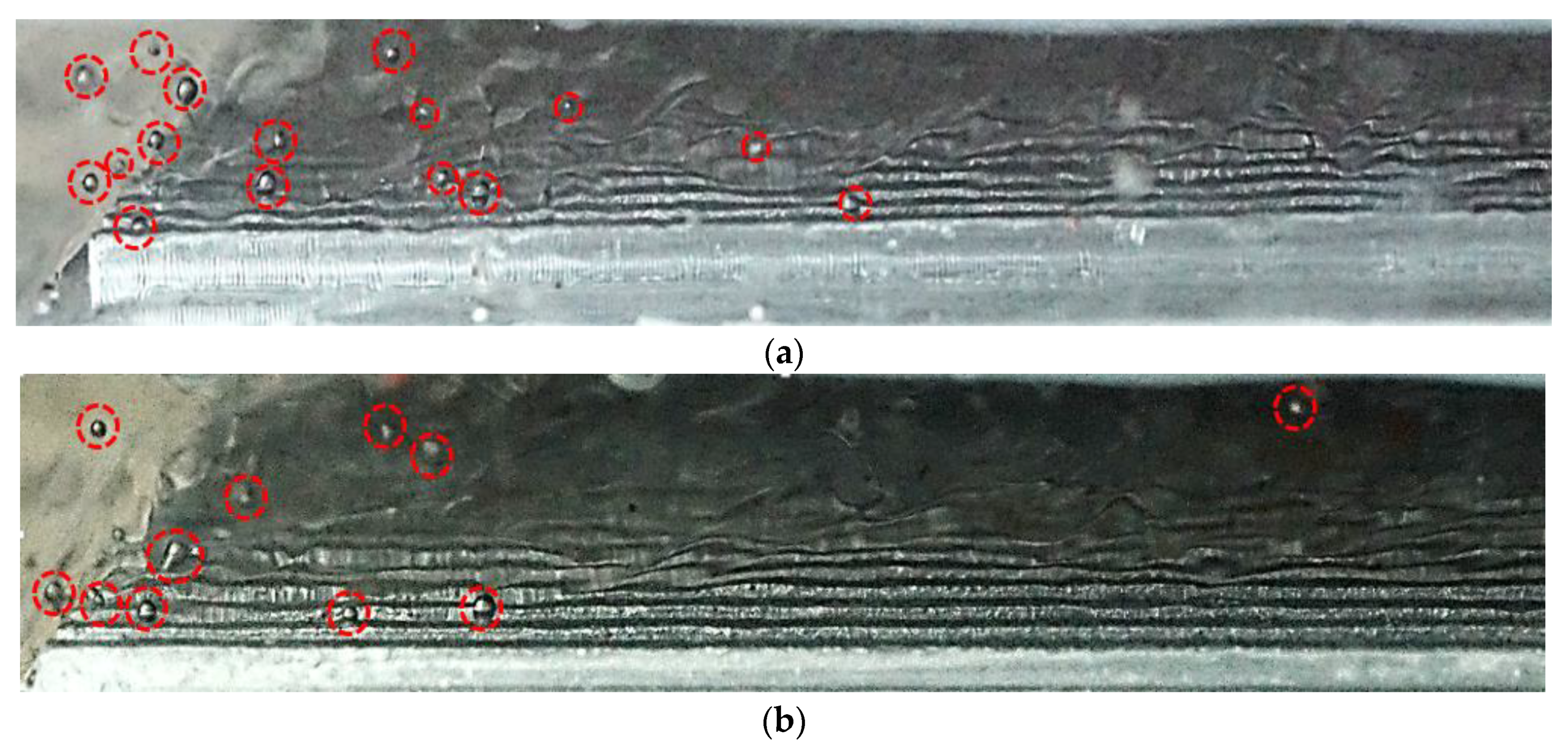
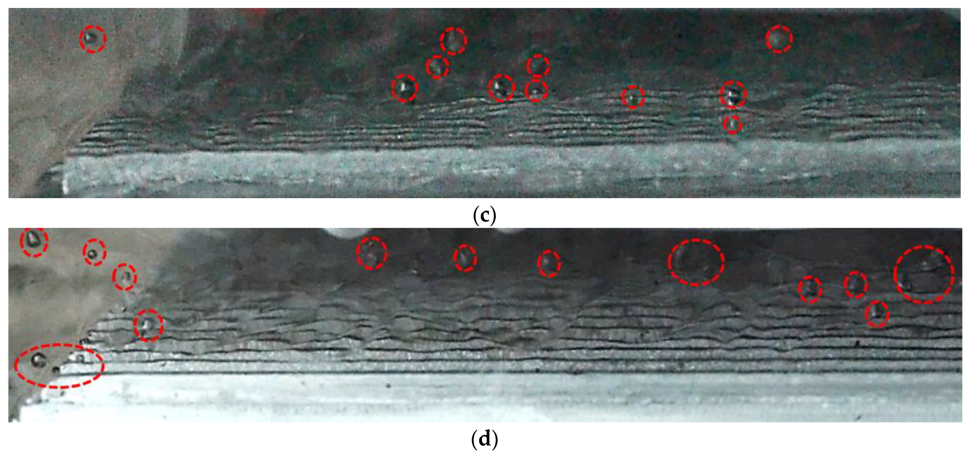
3.2. Boiling Phenomenon and Bubble Dynamics

To provide a better understanding of the boiling phenomenon in the channel, the visualisation of the bubble dynamics during the boiling process is discussed in this section. As the free stream flow hits the leading edge, the thermal boundary layer grows. As the temperature increases up to the saturation temperature, the phase-change occurs on the surface, leading to bubble generation on the active nucleation site. Equally important, the bubble nucleation is strongly affected by the test condition, and the present study reveals that the phenomenon is more pronounced in higher heat transfer coefficient cases (R1 and T1). From Figure 7, it can be observed that bubble dynamics are affected by the surface geometry and fluid flow rate. The comparison between R1, R2 and R3 surfaces at 170 W heat input shows that the R1 surface had the highest number of bubbles and detachments compared to the other surfaces. This observation is consistent with the higher heat transfer coefficient of the R1 surface, as discussed in Section 3.1. However, it is worth noting that at lower fluid flow rates, the bubble population on the surface appeared to be more crowded, which could cause a reduction in heat transfer performance due to the thermal resistance from the vapour. This effect was more pronounced in the R3 surface, which had the lowest heat transfer coefficient among the three surfaces due to the inability to detach the heat by the evaporation process. This indicates that the heat transfer coefficient has a direct influence on bubble dynamics during the boiling process.
Furthermore, the effect of mass flux on the bubble dynamics is presented in Table 4. The results show that the mass flux is a critical parameter that affects bubble dynamics during boiling. At low mass fluxes, bubbles tend to grow larger and detach from the surface more slowly due to weaker fluid flow. In contrast, at high mass fluxes, the fluid flow is stronger, which promotes bubble detachment and faster sliding on the surface. As a result, the time taken for the bubble to reach the detachment point may vary depending on the mass flux. In these illustrations, the mass flux varied between 13.1 kg/m2∙s and 19.7 kg/m2∙s. A bubble detaches after sliding on the surface in the direction of the fluid flow. This bubble sliding is the distinction between the pool and flow boiling, whereby the bubble is unable to accumulate on a surface due to the fluid flow.
As the mass flux rises, the inertial force from the fluid increases the sliding speed of the bubble. Whilst the distance taken before the bubble detaches was similar between these two test cases, the time taken for the bubble to reach that point was slightly different (1.6 s and 1.2 s for G = 13.1 kg/m2∙s and G = 19.7 kg/m2∙s, respectively) and was not linearly correlated with the fluid velocity. The results of the test case indicate that as the mass flux increases by half, the time taken for the bubble departure decreases by approximately 25%. This suggests that the effect of mass flux on bubble dynamics is non-linear and can have a significant impact on the overall heat transfer performance. As the fluid flows, the evaporative heat flux from the high mass flux is enhanced, allowing the average boiling heat transfer coefficient to rise. It should be noted that in this particular study, the observed vapour quality and Reynolds number were relatively small, ranging from 30 to 180. As a result, the impact of bulk fluid movement can be considered negligible.
This phenomenon is not limited to the specific surface studied in the experiment, as it has been observed in other surfaces as well. Thus, the impact of mass flux on bubble dynamics is an important consideration in understanding the heat transfer performance during boiling.

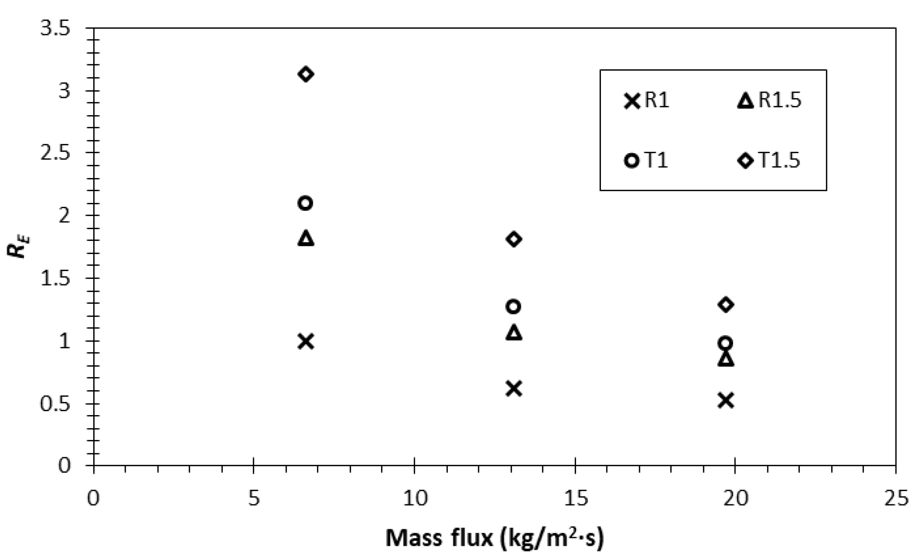
3.3. Enhancement Efficiency Analysis

As mentioned in the previous section, while flow boiling relies on the active enhancement by fluid flow to achieve a better cooling capacity than pool boiling, the external power required to flow the working fluid poses an additional challenge related to the pressure drop. Changes in particular parameters, such as channel geometry, can lead to a more significant heat transfer performance but may also increase power consumption due to a pressure drop. In this study, those two important parameters, heat transfer coefficient and required power, were analysed together in the form of flow boiling enhancement. First, the pressure drop was measured and estimated, as presented in Figure 8.
Finally, the enhancement was calculated by comparing the HTC and pressure drop to their reference value, which in this case was the R1 test case. This non-dimensional number representing the enhancement ratio is expressed as follows:
R E , x = h x / h R 1 Δ p x / Δ p R 1
where R E , x is the enhancement ratio of the test case x, and h x and Δ p x are the HTC and pressure drop of the test case x, while   h R 1 and Δ p R 1 are the HTC and pressure drop of the reference test case (R1) with the mass flux of 6.6 kg/m2∙s, respectively. The enhancement ratio of >1 means that the test case provided better cooling system efficiency than the reference test case, and vice versa. The enhancement ratios of all test cases are presented in Figure 9.
This result shows that the highest enhancement ratio was observed in the trapezoidal fin with a gap of 1.5 mm, especially at the mass flux of 6.6 kg/m2∙s. It is noteworthy that, although the heat transfer coefficient was at its lowest, the pressure drop in this test case was also the lowest. Compared to the rectangular fin with a gap of 1 mm, for instance, the heat transfer coefficient was 24% lower, whilst the pressure drop was 72% lower, resulting in the higher ‘efficiency’ of the enhancement. Meanwhile, the increase in the mass flux significantly raised the pressure drop up to 48%. On the other hand, the HTC enhancement of increasing the mass flux was restricted to below 30% (see Figure 5). Hence, the overall system efficiency reduced remarkably as the mass flux increased. This is a vital consideration in the design, whereby higher performance and high energy-saving efficiency should be considered together.

4. Conclusions

An experimental study investigating the heat transfer performance of flow boiling in a straight fin microchannel was conducted. The experimental study compared the performance of the HTC, pressure drop, and visualisation of the boiling phenomenon from various pin fin designs and dimensions. Some prominent results from the study are as follows:
  • The inclining trend of heat transfer coefficient with the rise in heat flux was indicated by the sharper boiling curves, whereby the lower surface temperature could be achieved at the same supplied heat flux. This was the result of the more bubbles being generated, increasing the contribution of the evaporative and quenching heat flux.
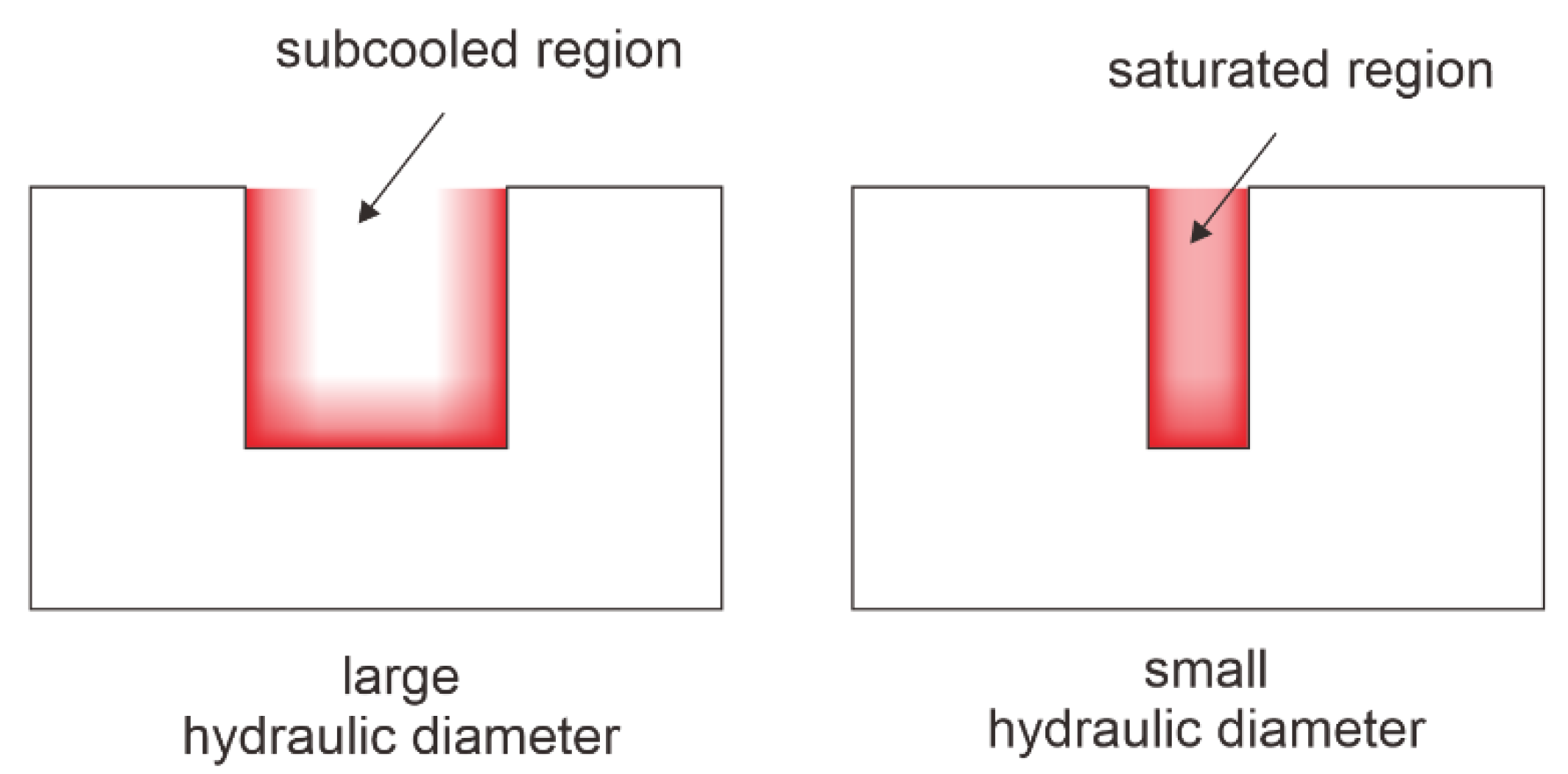
  • The cooling performance improved as the fin gap reduced up to 22.5% and 17.1% for rectangular and trapezoidal fins, respectively. The hydraulic diameter had an important impact on the heat transfer coefficient, whereby the lower diameter contributed to the more distributed saturated region. As the hydraulic diameter decreased, there would be more covered area to fulfil the requirement of the ONB, resulting in better cooling performance by the bubble nucleation process.
  • In general, the rectangular fin had a higher heat transfer coefficient than the trapezoidal fin. The effect of the total extended area was undermined by the effect of the hydraulic diameter. In order, the best test cases in terms of cooling performance were R1, T1, R1.5 and T1.5, with the highest observed at 5066.84 W/m2∙K.
  • Bubble sliding was observed during the boiling process. As the heat transfer coefficient increased, the bubbles were observed to exist in larger numbers but with a shorter period of detachment. It was found that there was no significant effect of mass flux on the bubble sliding distance.

Author Contributions

Conceptualisation, I.P., M.A.R. and A.W.; methodology, I.P., M.A.R. and C.D.W.; formal analysis, I.P., C.D.W. and A.E.W.; validation, C.D.W., A.E.W. and F.; result analysis, I.P. and M.A.R.; investigation, C.D.W., A.E.W. and F.; writing—original draft preparation, I.P. and M.A.R.; writing—review and editing, I.P. and A.W.; visualisation, C.D.W., A.E.W. and F.; supervision, I.P. and F.; funding acquisition, I.P. All authors have read and agreed to the published version of the manuscript.

Funding

This research was funded by Final Project Recognition Grant Universitas Gadjah Mada Number 3550/UN1.P.III/Dit-Lit/PT.01.05/2022.

Data Availability Statement

Not applicable.

Conflicts of Interest

The authors declare no conflict of interest.

Nomenclature

aSample length (mm)
AbaseArea of fin base (mm2)
AextArea of fin extended surface (mm2)
AtotTotal area of fin surface (mm2)
bSample width (mm)
CHFCritical heat flux
DhHydraulic diameter (mm)
GMass flux (kg/m2·s)
hFin height (mm)
hbBoiling heat transfer coefficient (W/m2·K)
PWetted perimeter (m)
qHeat flux (W/m2)
REEnhancement ratio (dimensionless)
sFin width (mm)
TsSurface temperature (K)
TsatSaturation temperature (K)
ΔpPressure drop (Pa)
ΔTeTsTsat, Excess temperature (K)
σUncertainty

References

  1. El-Genk, M.S. Nucleate boiling enhancements on porous graphite and microporous and macro—Finned copper surfaces nucleate boiling enhancements on porous graphite and microporous and macro—Finned copper surfaces. Heat Transfer. Eng. 2012, 33, 175–204. [Google Scholar] [CrossRef]
  2. Liang, G.; Mudawar, I. Review of pool boiling enhancement by surface modification. Int. J. Heat Mass Transf. 2021, 128, 892–933. [Google Scholar] [CrossRef]
  3. Giustini, G. Modelling of boiling flows for nuclear thermal hydraulics applications—A brief review. Invention 2020, 5, 47. [Google Scholar] [CrossRef]
  4. Kurul, N.; Podowski, M.Z. Multidimensional effects in forced convection subcooled boiling. In International Heat Transfer Conference Digital Library; Begel House Inc.: Danbury, CT, USA, 1990. [Google Scholar]
  5. Anderson, T.M.; Mudawar, I. Microelectronic cooling by enhanced pool boiling of a dielectric fluorocarbon liquid. J. Heat Transfer. 1989, 111, 752–759. [Google Scholar] [CrossRef]
  6. He, Z.; Yan, Y.; Zhang, Z. Thermal management and temperature uniformity enhancement of electronic devices by micro heat sinks: A review. Energy 2020, 216, 119223. [Google Scholar] [CrossRef]
  7. Sur, A.; Lu, Y.; Pascente, C.; Ruchhoeft, P.; Liu, D. Pool boiling heat transfer enhancement with electrowetting. Int. J. Heat Mass Transf. 2018, 120, 202–217. [Google Scholar] [CrossRef]
  8. Deng, D.; Zeng, L.; Sun, W. A review on flow boiling enhancement and fabrication of enhanced microchannels of microchannel heat sinks. Int. J. Heat Mass Transf. 2021, 175, 121332. [Google Scholar] [CrossRef]
  9. Milanova, D.; Kumar, R. Heat transfer behavior of silica nanoparticles in pool boiling. J. Heat Transf. 2018, 130, 042401. [Google Scholar] [CrossRef]
  10. Ho, J.Y.; Leong, K.C.; Yang, C.; Pranoto, I. An experimental study of carbon nanotube coatings for pool boiling heat transfer enhancement. In Proceedings of the International Heat Transfer Conference 15, Kyoto, Japan, 10–15 August 2014. [Google Scholar]
  11. Wei, J.J.; Honda, H. Effects of fin geometry on boiling heat transfer from silicon chips with micro-pin-fins immersed in FC-72. Int. J. Heat Mass Transf. 2003, 46, 4059–4070. [Google Scholar] [CrossRef]
  12. Shojaeian, M.; Kosar, A. Pool boiling and flow boiling on micro- and nanostructured surfaces. Exp. Therm. Fluid Sci. 2015, 63, 45–73. [Google Scholar] [CrossRef]
  13. Bian, H.; Kurwitz, C.; Sun, Z.; Cheng, K.; Chen, K. Enhanced nucleate boiling on 3D-printed micro-porous structured surface. Appl. Therm. Eng. 2018, 141, 422–434. [Google Scholar] [CrossRef]
  14. Pranoto, I.; Leong, K.C. An experimental study of flow boiling heat transfer from porous foam structures in a channel. Appl. Therm. Eng. 2014, 70, 100–114. [Google Scholar] [CrossRef]
  15. Harirchian, T.; Garimella, S.V. Microchannel size effects on local flow boiling heat transfer to a dielectric fluid. Int. J. Heat Mass Transfer 2008, 51, 3724–3735. [Google Scholar] [CrossRef] [Green Version]
  16. Deng, D.; Tang, Y.; Shao, H.; Zeng, J.; Zhou, W.; Liang, D. Effects of structural parameters on flow boiling performance of reentrant porous microchannels. J. Micromech. Microeng. 2014, 24, 065025. [Google Scholar] [CrossRef]
  17. Cheng, P.; Wu, H.Y.; Hong, F.J. Phase-change heat transfer in microsystems. J. Heat Transfer. 2006, 129, 101–108. [Google Scholar] [CrossRef] [Green Version]
  18. Ma, A.; Wei, J.; Yuan, M.; Fang, J. Enhanced flow boiling heat transfer of FC-72 on micro-pin-finned surfaces. Int. J. Heat Mass Transfer. 2009, 52, 2925–2931. [Google Scholar] [CrossRef]
  19. Law, M.; Lee, P. A comparative study of experimental flow boiling heat transfer and pressure characteristics in straight- and oblique-finned microchannels. Int. J. Heat Mass Transfer. 2015, 85, 797–810. [Google Scholar] [CrossRef]
  20. Prajapati, Y.K.; Pathak, M.; Khan, M.K. A comparative study of flow boiling heat transfer in three different configurations of microchannels. Int. J. Heat Mass Transf. 2015, 85, 711–722. [Google Scholar] [CrossRef]
  21. Sun, Y.; Zhang, L.; Xu, H.; Zhong, X. Flow boiling enhancement of FC-72 from microporous surfaces in minichannels. Exp. Therm. Fluid Sci. 2011, 35, 1418–1426. [Google Scholar] [CrossRef]
  22. Zhou, J.; Qiang, L.; Xuemei, C. Micro pin fins with topologically optimized configurations enhance flow boiling heat transfer in manifold microchannel heat sinks. Int. J. Heat Mass Transfer. 2023, 206, 123956. [Google Scholar] [CrossRef]
  23. Tian, Z.; Kun, L.; Yuan, Z.; Zhikang, H.; Shuming, X.; Wenzhong, G. Numerical simulation of microchannel flow boiling and critical heat flux under rolling motion. Int. J. Refrigeration. 2023, 145, 118–128. [Google Scholar] [CrossRef]
  24. Qi, H.; Fang, D.; Meng, X.; Wu, J. Liquid density of HFE-7000 and HFE-7100 from T = (283 to 363) K at pressures up to 100 MPa. J. Chem. Thermodyn. 2014, 77, 131–136. [Google Scholar] [CrossRef]
  25. An, B.; Duan, Y.; Yang, F.; Yang, Z. pvT property of HFE 7100 in the gaseous phase. J. Chem. Eng. Data. 2015, 60, 3289−3295. [Google Scholar] [CrossRef]
  26. Rausch, M.H.; Kretschmer, L.; Will, S.; Leipertz, A.; Froba, A.P. Density, surface tension, and kinematic viscosity of hydrofluoroethers HFE-7000, HFE-7100, HFE-7200, HFE-7300, and HFE-7500. J. Chem. Eng. Data. 2015, 60, 3759–3765. [Google Scholar] [CrossRef]
  27. Taylor, J.R. An Introduction to Error Analysis, 2nd ed.; University of Science Book: Sausalito, CA, USA, 1997. [Google Scholar]
  28. Pranoto, I.; Rahman, M.A.; Waluyo, J. The Role of Pin Fin Array Configurations and Bubble Characteristics on the Pool Boiling Heat Transfer Enhancement. Fluids 2022, 7, 232. [Google Scholar] [CrossRef]
  29. Pranoto, I.; Rahman, M.A.; Mahardika, P.A.P. Pool boiling heat transfer performance and bubble dynamics from pin fin-modified surfaces with geometrical shape variation. Energies 2022, 15, 1847–1858. [Google Scholar] [CrossRef]
  30. Vajc, V.; Moze, M.; Hadzic, A.; Sulc, R.; Golobic, I. Saturated and subcooled pool boiling heat transfer in mixtures of water and glycerin. Exp. Heat Transf. 2023, 36, 283–311. [Google Scholar] [CrossRef]
Figure 1. Experimental facility by (a) schematic diagram and (b) system configuration.
Fluids 08 00102 g001aFluids 08 00102 g001b
Figure 2. (a) Evaporator chamber of the experimental facility and (b) schematic diagram and sensors placement.
Fluids 08 00102 g002aFluids 08 00102 g002b
Figure 3. (a) Illustration and (b) example of actual image of straight fin samples employed in this study.
Fluids 08 00102 g003
Figure 4. Boiling curves of test case of test case (a) R1, (b) R1.5, (c) T1, and (d) T1.5.
Fluids 08 00102 g004aFluids 08 00102 g004b
Figure 5. Average boiling heat transfer coefficient among four different surfaces.
Fluids 08 00102 g005
Figure 6. Comparison of thermal boundary layers on large and small hydraulic diameters.
Fluids 08 00102 g006
Figure 7. Bubble (indicated by red dotted circles) dynamics of the (a) R1, (b) R1.5, (c) T1 and (d) T1.5 test cases at power input 170 W and G = 6.6 kg/m2∙s.
Fluids 08 00102 g007aFluids 08 00102 g007b
Figure 8. Pressure drops among four different surfaces.
Fluids 08 00102 g008
Figure 9. Enhancement ratio among four different surfaces.
Fluids 08 00102 g009
Table 1. Finned surface dimensions.
Test CaseProfiles (mm)h (mm)AextAbaseAtotAtot/Abase
R1Rectangular10.953602.447798381.41.75
R1.5Rectangular1.50.9253507.647798286.61.73
T1Trapezoidal10.952777.047797556.01.58
T1.5Trapezoidal1.50.9252685.4547797464.451.56
Table 2. Properties of HFE-7100 [24,25,26].
PropertiesValues
Boiling point (K)334.15
Specific heat (J/kg∙K)1170
Latent heat vaporisation (kJ/kg)112
Thermal conductivity (W/m∙K)0.068
Liquid density (kg/m3)1418.64
Vapour density (kg/m3)0.98
Kinematic viscosity (m2/s)3.008 × 10−7
Table 3. Summary of average heat transfer coefficient.
Test Case Average   Heat   Transfer   Coefficient   (hb, W/m2·K) Hydraulic Diameter (Dh, mm)
R14505.641.31
R1.53635.951.66
T14070.531.60
T1.53433.791.90
Table 4. Bubble (indicated by red dotted circles) lift-off mechanism in the R1 test case and input power of 170 W.
Time (s)G = 13.1 kg/m2∙sG = 19.7 kg/m2∙s
0.4Fluids 08 00102 i001Fluids 08 00102 i002
0.8Fluids 08 00102 i003Fluids 08 00102 i004
1.2Fluids 08 00102 i005Fluids 08 00102 i006
1.6Fluids 08 00102 i007Fluids 08 00102 i008
Disclaimer/Publisher’s Note: The statements, opinions and data contained in all publications are solely those of the individual author(s) and contributor(s) and not of MDPI and/or the editor(s). MDPI and/or the editor(s) disclaim responsibility for any injury to people or property resulting from any ideas, methods, instructions or products referred to in the content.

