
Hemodynamic Evaluation of a Centrifugal Left Atrial Decompression Pump for Heart Failure with Preserved Ejection Fraction
 , , ,
, , ,
Abstract
:1. Introduction
2. Materials and Methods
2.1. Design Features and Computational Modeling
2.1.1. Geometry and Design Features
2.1.2. Fluid Domain and Meshing
2.1.3. Simulation of the Hemodynamic Characteristics
2.1.4. Hemodynamics and SSS Calculation
2.2. Closed-Loop Test Bench for Hydraulic Performances
3. Results
3.1. Experimental Hydraulic Performances
3.2. Overall CFD Results and Experimental Comparison
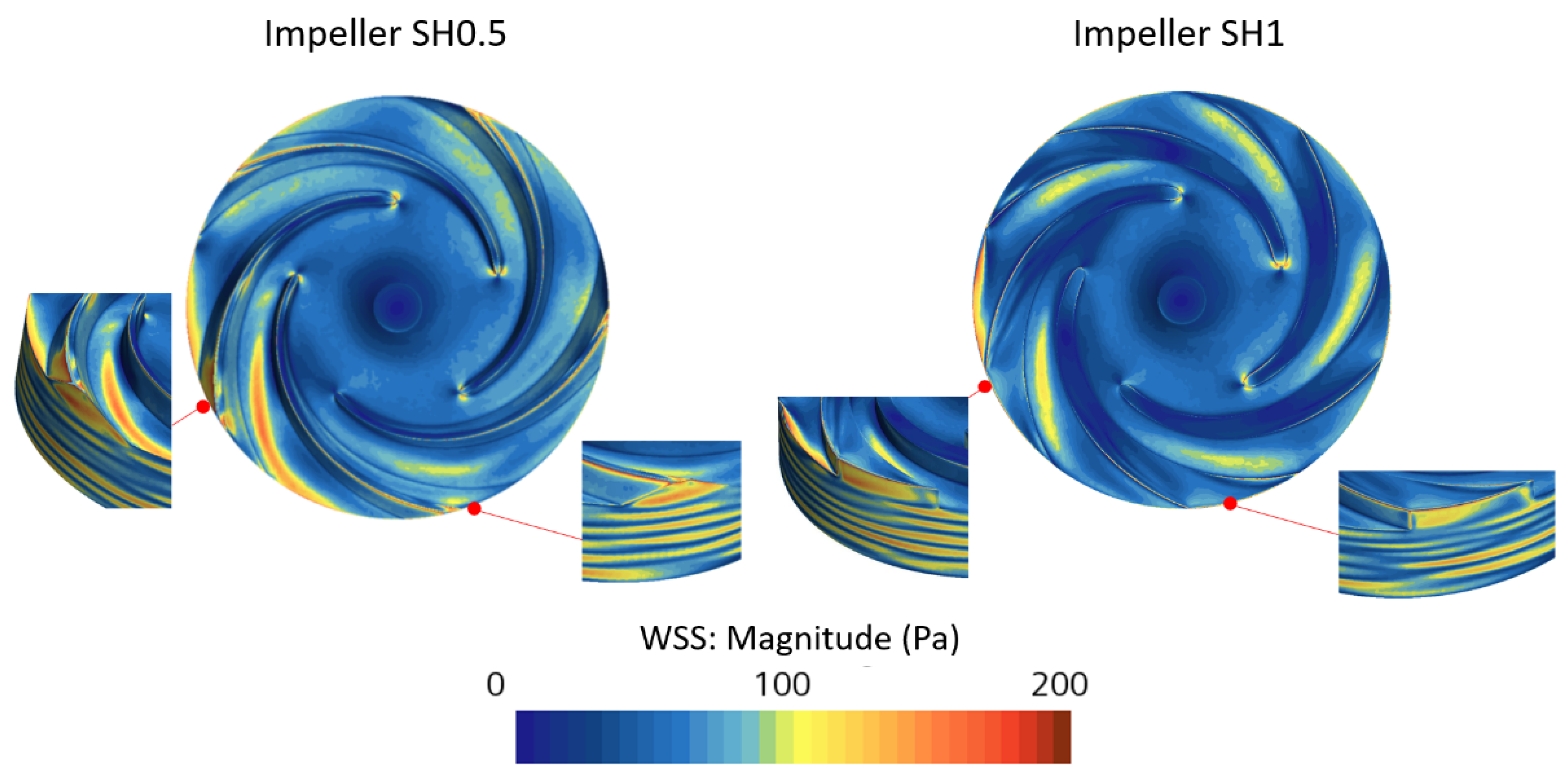
3.3. Hemocompatibility Analysis
4. Discussion
5. Conclusions
Author Contributions
Funding
Institutional Review Board Statement
Informed Consent Statement
Data Availability Statement
Conflicts of Interest
Nomenclature
| b2 | impeller outlet width, mm |
| D1 | impeller inlet diameter, mm |
| D2 | impeller outlet diameter, mm |
| HFpEF | heart failure with preserved ejection fraction |
| N | rotation speed, rpm |
| Q | flow rate, L/min |
| V/Vt | volume fraction, % |
| Vrel | relative velocity, m/s |
| Vorticity | vorticity magnitude, s−1 |
| WSS | Wall Shear Stress, Pa |
| Z | blades number |
| β1 | blade inlet angle, ° |
| β2 | blade outlet angle, ° |
| δLE | leading edge blade thickness, mm |
| δTE | trailing edge blade thickness, mm |
| ΔP | pressure gradient, mm Hg |
| Scalar Shear Stress (SSS), Pa |
References
- Bhatia, R.S.; Tu, J.V.; Lee, D.S.; Austin, P.C.; Fang, J.; Haouzi, A.; Gong, Y.; Liu, P.P. Outcome of Heart Failure with Preserved Ejection Fraction in a Population-Based Study. N. Engl. J. Med. 2006, 355, 260–269. [Google Scholar] [CrossRef] [PubMed] [Green Version]
- Little, W.C.; Applegate, R.J. Congestive heart failure: Systolic and diastolic function. J. Cardiothorac. Vasc. Anesth. 1993, 7, 2–5. [Google Scholar] [CrossRef] [PubMed]
- Yoon, S.; Eom, G.H. Heart failure with preserved ejection fraction: Present status and future directions. Exp. Mol. Med. 2019, 51, 1–9. [Google Scholar] [CrossRef] [PubMed] [Green Version]
- Cleland, J.G.F.; Tendera, M.; Adamus, J.; Freemantle, N.; Polonski, L.; Taylor, J. The perindopril in elderly people with chronic heart failure (PEP-CHF) study. Eur. Heart J. 2006, 27, 2338–2345. [Google Scholar] [CrossRef] [Green Version]
- Yusuf, S.; Pfeffer, M.A.; Swedberg, K.; Granger, C.B.; Held, P.; McMurray, J.J.; Michelson, E.L.; Olofsson, B.; Östergren, J. Effects of candesartan in patients with chronic heart failure and preserved left-ventricular ejection fraction: The CHARM-Preserved Trial. Lancet 2003, 362, 777–781. [Google Scholar] [CrossRef]
- Massie, B.M.; Carson, P.E.; McMurray, J.J.; Komajda, M.; McKelvie, R.; Zile, M.R.; Anderson, S.; Donovan, M.; Iverson, E.; Staiger, C.; et al. Irbesartan in Patients with Heart Failure and Preserved Ejection Fraction. N. Engl. J. Med. 2008, 359, 2456–2467. [Google Scholar] [CrossRef] [Green Version]
- Hernandez, A.F.; Hammill, B.G.; O’Connor, C.M.; Schulman, K.A.; Curtis, L.H.; Fonarow, G.C. Clinical Effectiveness of Beta-Blockers in Heart Failure: Findings From the OPTIMIZE-HF (Organized Program to Initiate Lifesaving Treatment in Hospitalized Patients with Heart Failure) Registry. J. Am. Coll. Cardiol. 2009, 53, 184–192. [Google Scholar] [CrossRef] [Green Version]
- Owan, T.E.; Hodge, D.O.; Herges, R.M.; Jacobsen, S.J.; Roger, V.L.; Redfield, M.M. Trends in Prevalence and Outcome of Heart Failure with Preserved Ejection Fraction. N. Engl. J. Med. 2006, 355, 251–259. [Google Scholar] [CrossRef] [Green Version]
- Shah, S.J.; Borlaug, B.A.; Chung, E.S.; Cutlip, D.E.; Debonnaire, P.; Fail, P.S.; Gao, Q.; Hasenfuß, G.; Kahwash, R.; Kaye, D.M.; et al. Atrial shunt device for heart failure with preserved and mildly reduced ejection fraction (REDUCE LAP-HF II): A randomised, multicentre, blinded, sham-controlled trial. Lancet 2022, 399, 1130–1140. [Google Scholar] [CrossRef]
- Applegate, R.J.; Santamore, W.P.; Klopfenstein, H.S.; Little, W.C. External pressure of undisturbed left ventricle. Am. J. Physiol. 1990, 258, H1079–H1086. [Google Scholar] [CrossRef]
- Assanelli, D.; Lew, W.Y.; Shabetai, R.; LeWinter, M.M. Influence of the pericardium on right and left ventricular filling in the dog. J. Appl. Physiol. 1987, 63, 1025–1032. [Google Scholar] [CrossRef] [PubMed]
- Freeman, G.L.; LeWinter, M.M. Pericardial adaptations during chronic cardiac dilation in dogs. Circ. Res. 1984, 54, 294–300. [Google Scholar] [CrossRef] [PubMed] [Green Version]
- Glantz, S.A.; Misbach, G.A.; Moores, W.Y.; Mathey, D.G.; Lekven, J.; Stowe, D.F.; Parmley, W.W.; Tyberg, J.V. The pericardium substantially affects the left ventricular diastolic pressure-volume relationship in the dog. Circ. Res. 1978, 42, 433–441. [Google Scholar] [CrossRef] [PubMed] [Green Version]
- LeWinter, M.M.; Pavelec, R. Influence of the pericardium on left ventricular end-diastolic pressure-segment relations during early and later stages of experimental chronic volume overload in dogs. Circ. Res. 1982, 50, 501–509. [Google Scholar] [CrossRef] [Green Version]
- Slinker, B.K.; Ditchey, R.V.; Bell, S.P.; LeWinter, M.M. Right heart pressure does not equal pericardial pressure in the potassium chloride-arrested canine heart in situ. Circulation 1987, 76, 357–362. [Google Scholar] [CrossRef] [PubMed] [Green Version]
- Borlaug, B.A.; Carter, R.E.; Melenovsky, V.; De Simone, C.V.; Gaba, P.; Killu, A.; Naksuk, N.; Lerman, L.; Asirvatham, S.J. Percutaneous Pericardial Resection: A Novel Potential Treatment for Heart Failure with Preserved Ejection Fraction. Circ. Heart Fail. 2017, 10, e003612. [Google Scholar] [CrossRef] [Green Version]
- Gude, E.; Fiane, A.E. Can mechanical circulatory support be an effective treatment for HFpEF patients? Heart Fail. Rev. 2021, 28, 297–305. [Google Scholar] [CrossRef]
- Fukamachi, K.; Horvath, D.J.; Karimov, J.H.; Kado, Y.; Miyamoto, T.; Kuban, B.D.; Starling, R.C. Left atrial assist device to treat patients with heart failure with preserved ejection fraction: Initial in vitro study. J. Thorac. Cardiovasc. Surg. 2021, 162, 120–126. [Google Scholar] [CrossRef]
- Denisov, M.V.; Telyshev, D.V.; Selishchev, S.V.; Romanova, A.N. Investigation of Hemocompatibility of Rotary Blood Pumps: The Case of the Sputnik Ventricular Assist Device. Biomed. Eng. 2019, 53, 181–184. [Google Scholar] [CrossRef]
- Qu, Y.; Guo, Z.; Zhang, J.; Li, G.; Zhang, S.; Li, D. Hemodynamic investigation and in vitro evaluation of a novel mixed-flow blood pump. Artif. Organs 2022, 46, 1533–1543. [Google Scholar] [CrossRef]
- Pinney, S.P.; Anyanwu, A.C.; Lala, A.; Teuteberg, J.J.; Uriel, N.; Mehra, M.R. Left Ventricular Assist Devices for Lifelong Support. J. Am. Coll. Cardiol. 2017, 69, 2845–2861. [Google Scholar] [CrossRef]
- Marcel, L.; Specklin, M.; Kouidri, S. The evolution of long-term pediatric ventricular assistance devices: A critical review. Expert Rev. Med. Devices 2021, 18, 783–798. [Google Scholar] [CrossRef] [PubMed]
- Bakir, F.; Rey, R.; Noguera, R.; Massouh, F. Computer aided design of helico-centrifugal pumps. Proc. ASME Second Pump. Mach. Symp. 1993, 154, 63–74. [Google Scholar]
- Fraser, K.H.; Zhang, T.; Taskin, M.E.; Griffith, B.P.; Wu, Z.J. A quantitative comparison of mechanical blood damage parameters in rotary ventricular assist devices: Shear stress, exposure time and hemolysis index. J. Biomech. Eng. 2012, 134, 81002. [Google Scholar] [CrossRef] [PubMed]
- Wiegmann, L.; Boës, S.; de Zélicourt, D.; Thamsen, B.; Schmid Daners, M.; Meboldt, M.; Kurtcuoglu, V. Blood Pump Design Variations and Their Influence on Hydraulic Performance and Indicators of Hemocompatibility. Ann. Biomed. Eng. 2018, 46, 417–428. [Google Scholar] [CrossRef] [PubMed]
- Wang, Y.; Shen, P.; Zheng, M.; Fu, P.; Liu, L.; Wang, J.; Yuan, L. Influence of impeller speed patterns on hemodynamic characteristics and hemolysis of the blood pump. Appl. Sci. 2019, 9, 4689. [Google Scholar] [CrossRef] [Green Version]
- Gil, A.; Navarro, R.; Quintero, P.; Mares, A.; Pérez, M.; Montero, J.A. CFD analysis of the HVAD’s hemodynamic performance and blood damage with insight into gap clearance. Biomech. Model. Mechanobiol. 2022, 21, 1201–1215. [Google Scholar] [CrossRef]
- Scardulla, F.; Agnese, V.; Romano, G.; Di Gesaro, G.; Sciacca, S.; Bellavia, D.; Clemenza, F.; Pilato, M.; Pasta, S. Modeling Right Ventricle Failure after Continuous Flow Left Ventricular Assist Device: A Biventricular Finite-Element and Lumped-Parameter Analysis. Cardiovasc. Eng. Technol. 2018, 9, 427–437. [Google Scholar] [CrossRef]
- Scardulla, F.; Pasta, S.; D’Acquisto, L.; Sciacca, S.; Agnese, V.; Vergara, C.; Quarteroni, A.; Clemenza, F.; Bellavia, D.; Pilato, M. Shear stress alterations in the celiac trunk of patients with a continuous-flow left ventricular assist device as shown by in-silico and in-vitro flow analyses. J. Heart Lung Transplant. 2017, 36, 906–913. [Google Scholar] [CrossRef]
- Antonuccio, M.N.; Mariotti, A.; Fanni, B.M.; Capellini, K.; Capelli, C.; Sauvage, E.; Celi, S. Effects of Uncertainty of Outlet Boundary Conditions in a Patient-Specific Case of Aortic Coarctation. Ann. Biomed. Eng. 2021, 49, 3494–3507. [Google Scholar] [CrossRef]
- Bozzi, S.; Morbiducci, U.; Gallo, D.; Ponzini, R.; Rizzo, G.; Bignardi, C.; Passoni, G. Uncertainty propagation of phase contrast-MRI derived inlet boundary conditions in computational hemodynamics models of thoracic aorta. Comput. Methods Biomech. Biomed. Eng. 2017, 20, 1104–1112. [Google Scholar] [CrossRef] [PubMed] [Green Version]
- Morbiducci, U.; Ponzini, R.; Gallo, D.; Bignardi, C.; Rizzo, G. Inflow boundary conditions for image-based computational hemodynamics: Impact of idealized versus measured velocity profiles in the human aorta. J. Biomech. 2013, 46, 102–109. [Google Scholar] [CrossRef] [PubMed]
- Gallo, D.; De Santis, G.; Negri, F.; Tresoldi, D.; Ponzini, R.; Massai, D.; Deriu, M.A.; Segers, P.; Verhegghe, B.; Rizzo, G.; et al. On the use of in vivo measured flow rates as boundary conditions for image-based hemodynamic models of the human aorta: Implications for indicators of abnormal flow. Ann. Biomed. Eng. 2012, 40, 729–741. [Google Scholar] [CrossRef] [PubMed]
- Mariotti, A.; Boccadifuoco, A.; Celi, S.; Salvetti, M.V. Hemodynamics and stresses in numerical simulations of the thoracic aorta: Stochastic sensitivity analysis to inlet flow-rate waveform. Comput. Fluids 2021, 230, 105123. [Google Scholar] [CrossRef]
- Romanova, A.N.; Pugovkin, A.A.; Denisov, M.V.; Ephimov, I.A.; Gusev, D.V.; Walter, M.; Groth, T.; Bockeria, O.L.; Le, T.G.; Satyukova, A.S.; et al. Hemolytic Performance in Two Generations of the Sputnik Left Ventricular Assist Device: A Combined Numerical and Experimental Study. J. Funct. Biomater. 2022, 13, 7. [Google Scholar] [CrossRef]
- Horobin, J.T.; Sabapathy, S.; Simmonds, M.J. Red blood cell tolerance to shear stress above and below the subhemolytic threshold. Biomech. Model. Mechanobiol. 2020, 19, 851–860. [Google Scholar] [CrossRef]
- Thamsen, B.; Blümel, B.; Schaller, J.; Paschereit, C.O.; Affeld, K.; Goubergrits, L.; Kertzscher, U. Numerical Analysis of Blood Damage Potential of the HeartMate II and HeartWare HVAD Rotary Blood Pumps. Artif. Organs 2015, 39, 651–659. [Google Scholar] [CrossRef]
- Song, J.; Marcel, L.; Specklin, M.; Lescroart, M.; Hébert, J.L.; Kouidri, S. Numerical study of hemolysis induced by shear stress at the junction between aorta and ventricular assistance device outflow graft. Int. J. Heat Fluid Flow 2022, 95, 108953. [Google Scholar] [CrossRef]
- Granzhan, A. Synthesis and Studies of Annelated Quinolizinium Derivatives as Versatile Constructs for Fluorescent Probes and Ligands for Triple-Helical and Abasic DNA Structures, Universität Siegen, 2006. pp. 149–150. Available online: https://www.researchgate.net/publication/277860842_Synthesis_and_studies_of_annelated_quinolizinium_derivatives_as_versatile_constructs_for_fluorescent_probes_and_ligands_for_triple-helical_and_abasic_DNA_structures (accessed on 1 January 2023).
- Kim, S.; Prasad, B.; Kim, J.K. Alignment of Microbeads Using Spinning Helical Minichannel Cartridge. J. Korean Soc. Vis. 2016, 14, 38–45. [Google Scholar] [CrossRef] [Green Version]
- Conner, K.; Cuthbert, J. Corrosion-Inhibited Propyleneglycol/Glycerin Compositions. U.S. Patent WO2010/008951 A, 21 January 2010. [Google Scholar]
- Telyshev, D.; Denisov, M.; Pugovkin, A.; Selishchev, S.; Nesterenko, I. The Progress in the Novel Pediatric Rotary Blood Pump Sputnik Development. Artif. Organs 2018, 42, 432–443. [Google Scholar] [CrossRef]
- Viola, F.; Jermyn, E.; Warnock, J.; Querzoli, G.; Verzicco, R. Left Ventricular Hemodynamics with an Implanted Assist Device: An In Vitro Fluid Dynamics Study. Ann. Biomed. Eng. 2019, 47, 1799–1814. [Google Scholar] [CrossRef] [PubMed]
- Li, Y.; Xi, Y.; Wang, H.; Sun, A.; Deng, X.; Chen, Z.; Fan, Y. A new way to evaluate thrombotic risk in failure heart and ventricular assist devices. Med. Nov. Technol. Devices 2022, 16, 100135. [Google Scholar] [CrossRef]
- Malone, G.; Abdelsayed, G.; Bligh, F.; Al Qattan, F.; Syed, S.; Varatharajullu, P.; Msellati, A.; Mwipatayi, D.; Azhar, M.; Malone, A.; et al. Advancements in left ventricular assist devices to prevent pump thrombosis and blood coagulopathy. J. Anat. 2022, 242, 29–49. [Google Scholar] [CrossRef]
- Chiu, W.-C.; Slepian, M.J.; Bluestein, D. Thrombus formation patterns in the HeartMate II ventricular assist device: Clinical observations can be predicted by numerical simulations. ASAIO J. 2014, 60, 237–240. [Google Scholar] [CrossRef] [PubMed] [Green Version]
- Thamsen, B.; Mevert, R.; Lommel, M.; Preikschat, P.; Gaebler, J.; Krabatsch, T.; Kertzscher, U.; Hennig, E.; Affeld, K. A two-stage rotary blood pump design with potentially lower blood trauma: A computational study. Int. J. Artif. Organs 2016, 39, 178–183. [Google Scholar] [CrossRef] [PubMed]
- Chan, C.H.H.; Ki, K.K.; Chu, I.Y.; Rolls, J.; Morris, S.; Lee, T.J.; Bindorfer, S.; Pauls, J.P.; Idachi, I.; Fraser, J.F. In vitro Hemocompatibility Evaluation of the HeartWare Ventricular Assist Device under Systemic, Pediatric and Pulmonary Support Conditions. ASAIO J. 2021, 67, 270–275. [Google Scholar] [CrossRef]
- Telyshev, D.V.; Denisov, M.V.; Selishchev, S.V. The Effect of Rotor Geometry on the H−Q Curves of the Sputnik Implantable Pediatric Rotary Blood Pump. Biomed. Eng. 2017, 50, 420–424. [Google Scholar] [CrossRef]
- Korakianitis, T.; Rezaienia, M.A.; Paul, G.M.; Rahideh, A.; Rothman, M.T.; Mozafari, S. Optimization of centrifugal pump characteristic dimensions for mechanical circulatory support devices. ASAIO J. 2016, 62, 545–551. [Google Scholar] [CrossRef]
- Kim, N.J.; Diao, C.; Ahn, K.H.; Lee, S.J.; Kameneva, M.V.; Antaki, J.F. Parametric study of blade tip clearance, flow rate, and impeller speed on blood damage in rotary blood pump. Artif. Organs 2009, 33, 468–474. [Google Scholar] [CrossRef]
- Ozturk, C.; Aka, I.B.; Lazoglu, I. Effect of blade curvature on the hemolytic and hydraulic characteristics of a centrifugal blood pump. Int. J. Artif. Organs 2018, 41, 730–737. [Google Scholar] [CrossRef]
- Fang, P.; Du, J.; Yu, S. Impeller (straight blade) design variations and their influence on the performance of a centrifugal blood pump. Int. J. Artif. Organs 2020, 43, 782–795. [Google Scholar] [CrossRef] [PubMed]
- Li, Y.; Yu, J.; Wang, H.; Xi, Y.; Deng, X.; Chen, Z.; Fan, Y. Investigation of the influence of blade configuration on the hemodynamic performance and blood damage of the centrifugal blood pump. Artif. Organs 2022, 46, 1817–1832. [Google Scholar] [CrossRef] [PubMed]


| Impeller SH0.5 | Impeller SH1 | |
|---|---|---|
| Impeller CAD |  |  |
| δLE-Hub | 1.00 | 1.00 |
| δTE-Hub | 3.68 | 3.68 |
| δLE-Shroud | 0.5 | 1.00 |
| δTE-Shroud | 0.5 | 3.68 |
| β1 | 15 | 15 |
| Β2 | 24 | 24 |
| Z | 5 | 5 |
| D1 | 17.5 | 17.5 |
| D2 | 35 | 35 |
 | ||
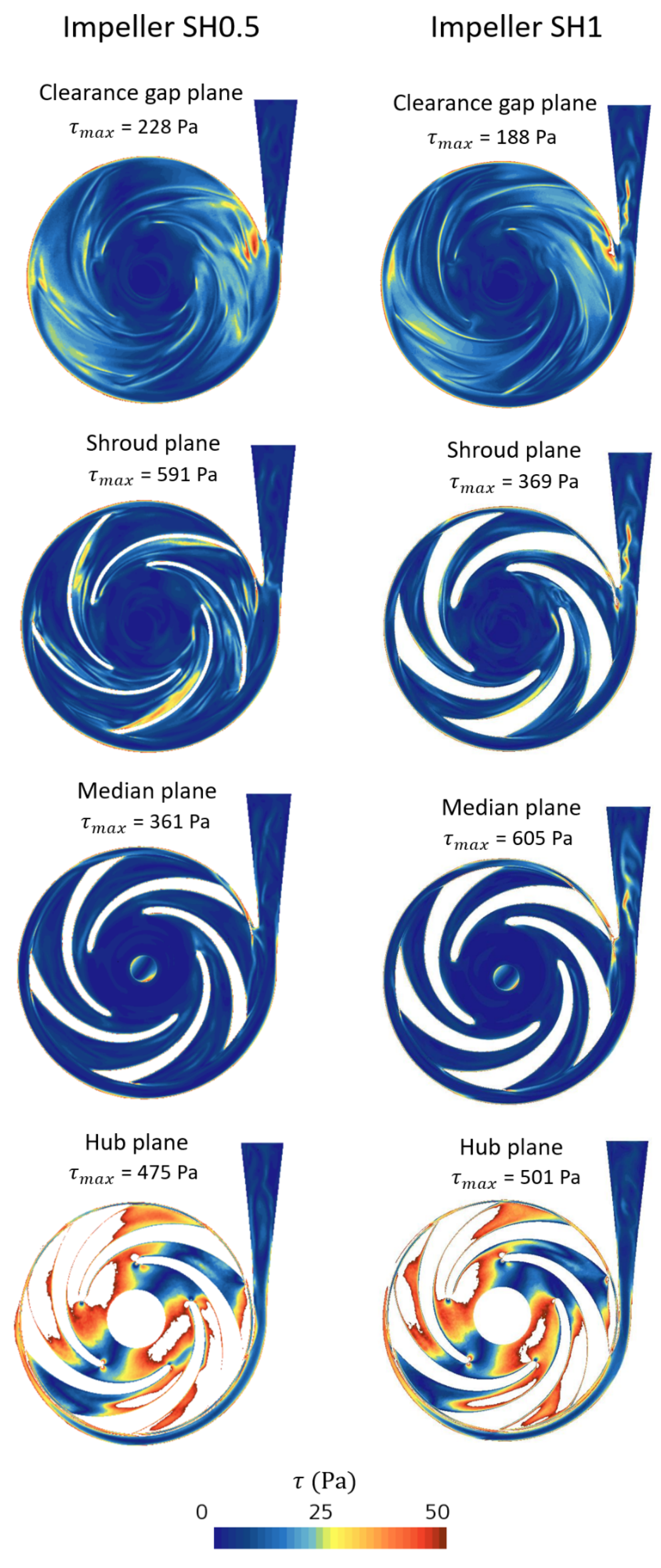
| Plan Name | Impeller SH0.5 | Impeller SH1 |
|---|---|---|
| Clearance gap plane | 74 × 103 | 52 × 103 |
| Shroud plane | 177 × 103 | 161 × 103 |
| Median plane | 86 × 103 | 157 × 103 |
| Hub plane | 108 × 103 | 116 × 103 |
Disclaimer/Publisher’s Note: The statements, opinions and data contained in all publications are solely those of the individual author(s) and contributor(s) and not of MDPI and/or the editor(s). MDPI and/or the editor(s) disclaim responsibility for any injury to people or property resulting from any ideas, methods, instructions or products referred to in the content. |
© 2023 by the authors. Licensee MDPI, Basel, Switzerland. This article is an open access article distributed under the terms and conditions of the Creative Commons Attribution (CC BY) license (https://creativecommons.org/licenses/by/4.0/).
Share and Cite
Abbasnezhad, N.; Specklin, M.; Bakir, F.; Leprince, P.; Danial, P. Hemodynamic Evaluation of a Centrifugal Left Atrial Decompression Pump for Heart Failure with Preserved Ejection Fraction. Bioengineering 2023, 10, 366. https://doi.org/10.3390/bioengineering10030366
Abbasnezhad N, Specklin M, Bakir F, Leprince P, Danial P. Hemodynamic Evaluation of a Centrifugal Left Atrial Decompression Pump for Heart Failure with Preserved Ejection Fraction. Bioengineering. 2023; 10(3):366. https://doi.org/10.3390/bioengineering10030366
Chicago/Turabian StyleAbbasnezhad, Navideh, Mathieu Specklin, Farid Bakir, Pascal Leprince, and Pichoy Danial. 2023. "Hemodynamic Evaluation of a Centrifugal Left Atrial Decompression Pump for Heart Failure with Preserved Ejection Fraction" Bioengineering 10, no. 3: 366. https://doi.org/10.3390/bioengineering10030366