Article

Scour Reduction around Bridge Pier Using the Airfoil-Shaped Collar

1
Civil Engineering Department, National Institute of Technology Warangal, Warangal 506004, India
2
Faculty of Engineering and Informatics, University of Bradford, Bradford BD7 1DP, UK
*
Authors to whom correspondence should be addressed.
Hydrology 2023, 10(4), 77; https://doi.org/10.3390/hydrology10040077
Submission received: 20 January 2023 / Revised: 25 March 2023 / Accepted: 27 March 2023 / Published: 30 March 2023
(This article belongs to the Special Issue Advances in Catchments Hydrology and Sediment Dynamics)

Abstract

:
Scouring around the bridge pier is a natural and complex phenomenon that results in bridge failure. Failure of bridges have potential devastation and public safety and economic loss, which lead to political consequences and environmental impacts. Therefore, it is essential to countermeasure the scour around the bridge pier. This paper studies the effects of four different airfoil-shaped collars (i.e., b c 1 = 1.5b, b c 2 = 2.0b, b c 3 = 2.5b and b c 4 = 3.0b, where b c and b are the diameter of the airfoil-shaped collar and pier, respectively) as a scour countermeasure. All the experiments are conducted under clear water conditions with uniform sediment and a constant water depth (y) of 10 cm. Airfoil-shaped collar is placed at four elevations, i.e., bed level, y/4, y/2 and 3y/4 above the sediment bed level. It is observed that the maximum percentages of scour reduction of 86, 100 and 100% occurred due to protection provided by the collar b c 2 , b c 3 and b c 4 , respectively, at sediment bed level. So, collars b c 2 , b c 3 and b c 4 are efficient at the sediment bed level. The profiles of scour hole show that the length of the transverse scour hole is greater than that of the longitudinal one. Numerical investigation of the morphological changes in sediment bed and scour depth contours is developed using the FLOW-3D for the pier with and without the airfoil-shaped collar.

1. Introduction

In the alluvial bed foundation of a bridge pier, scouring is one of the primary causes of failure [1,2]. Scouring is the removal of bed materials due to the action of flowing water. It is classified into three categories, i.e., general, contraction and local scour. The local scour around the bridge is a significant problem worldwide [1,3,4,5]. Scour hole characteristics mainly depend upon the erosion and deposition occurring due to the river flow influenced by geological and climate changes [6]. Failures of bridges threaten public safety and economic loss leading to political consequences and environmental impacts [7,8].
Between 1961 and 1974, it is observed that 46 out of 86 bridges were failed due to scour in US [9]. In 1973, the US Federal Highway Administration (FHWA) surveyed 383 bridges, out of which 20% and 70% of bridges failed due to scour around the pier and abutment, respectively. In the US, between 1989 and 2000, more than 50% of bridges failed due to flood and scour in 500 instances of bridge damage [10]. From 1980 to 1990, in northeastern and midwestern USA, more than 2500 bridges were damaged (affected) by flood and scour [11,12]. In 1993, damage of USD 20 million was caused in coastal regions resulting in the failure of 20 bridges due to waves and scour around the pier [13]. In 1993, during a single flood event in the upstream and downstream of the Missouri river basin, at least 22 out of 28 bridges on the waterway experienced some form of distress due to scour. The associated repair costs were more than USD 8 million. About 60% of bridges failed due to scour reported by the National Cooperative Highway Research Program (NCHRP). Between 2000 and 2014, around 30% of bridge failures in China were due to scour around bridge piers [9]. In the US, till 2009, more than 20,904 bridges were critically scoured, and 80,000 bridges were scour-susceptible [11]. In 2010, The AASHTO LRFD Bridge Design Specification stated that “A majority of bridge failure in the United States and elsewhere is the result of scour”. It is very well known that a bridge construction cost is gigantic, and the failure of a bridge causes more irretrievable losses. Scour around the pier is the main reason for the washing away of the bridge near Belgaon in Odisha, India, and the collapse of Chadoora bridge in Budgum district, India [8].
Local scour around the bridge pier is a result of a complex phenomenon from the interaction of water and sediment in a three-dimensional flow field [2,14,15,16], which results in the failure of bridges, and it is not always foreseeable at the design stage but emerges later [17,18,19,20]. Therefore, it is essential to countermeasure the scour around the bridge pier [21,22]. Countermeasure is defined as something used to monitor, inhibit, change, delay or minimize stream instability and bridge scour problems. It is highly beneficial because it solves the existing scour problem or mitigates future scour problems. There are many countermeasures used today. One of the major and active research areas is pier modifications using collars. The collar is simply a flat horizontal disk, which is mounted around the bridge pier. The collar impedes the downflow and horseshoe vortex along the face of the pier [17,23,24,25,26,27]. The shape of the collar is usually rectangular, circular and lenticular. The performance of the collar is evaluated on the basis of collar diameter (width) and position of it. The collar should be as small as possible so that it is less intrusive to the surrounding environment, easier to fabricate, requires less material and is less expensive. The impact of the collar on scour depth around the bridge pier is studied by several investigators [9,20,21,22,24,25,26,27,28,29,30,31,32,33]. Chen et al. [26] conducted laboratory experiments with a single hook and numerical simulation by FLOW-3D with double hook, using collar widths of 1.25b and hook height of 0.25b where b = pier diameter. The pier with a single hooked collar placed on the bed reduced scouring by 42%, and a pier with a double hooked collar placed on the bed reduced scouring by 50%. The research organization of the paper is as follows:
(a)
Experiments are carried out to study the reduction of scour around the bridge pier with and without an airfoil-shaped collar, which is placed at four locations under clear water conditions.
(b)
This paper estimated the percentage of scour reduction and efficiency of airfoil-shaped collars.
(c)
Experimental results are also validated with numerically simulated results using FLOW-3D.
(d)
Morphological changes, scour depth contours and streamlines are plotted with and without the airfoil-shaped collar.

2. Dimensional Analysis

Factors affecting the time-dependent scour depth ( d t ) around the bridge pier are:
(a)
Flow geometry: width of channel ( B ), diameter of pier ( b ), diameter of airfoil-shaped collar ( b c ), thickness of collar ( t c ), length of airfoil-shaped collar ( L c ), elevation of collar from the sediment bed (z).
(b)
Flow properties: water depth ( y ), approach flow velocity ( V ), acceleration due to gravity ( g ).
(c)
Fluid properties: density of fluid ( ρ ), kinematic viscosity ( ν ).
(d)
Bed properties: median particle size of sediment bed ( d 50 ), density of sediment bed ( ρ s ), standard deviation ( σ ).
(e)
Time: equilibrium time ( T ).
d t is represented by a functional relationship:
f 1   d t ,   B ,   b ,   b c ,   t c ,   L c ,   z ,   g ,   y ,   V ,   ρ ,   ν ,   d 50 ,   ρ s ,   σ ,   T = 0
Using the Buckingham π theorem, the dimensionless form is obtained as follows:
f 2 = d t b ,   B b , y b ,   b c b ,   t c b ,   L c b ,   z b ,   V T b ,   V b ν ,   ρ s ρ ,   g y V 2
Constants in experimental runs are B ,   b ,   t c ,   ρ ,   ν ,   d 50 ,   ρ s ,   σ , z b ,   g y V 2  ( 1 / F r 2 , F r : Froude number) and V b ν (Reynolds number). The effects of constant terms in experimental runs could be neglected, and Equation (2) may be simplified as Equation (3).
f 3 = d t b ,   b c b ,   L c b ,   V T b
where d t b is dimensionless scour depth, b c b is the proportion of collar diameter to pier diameter, L c b is length proportion to pier diameter and V T b dimensionless time.

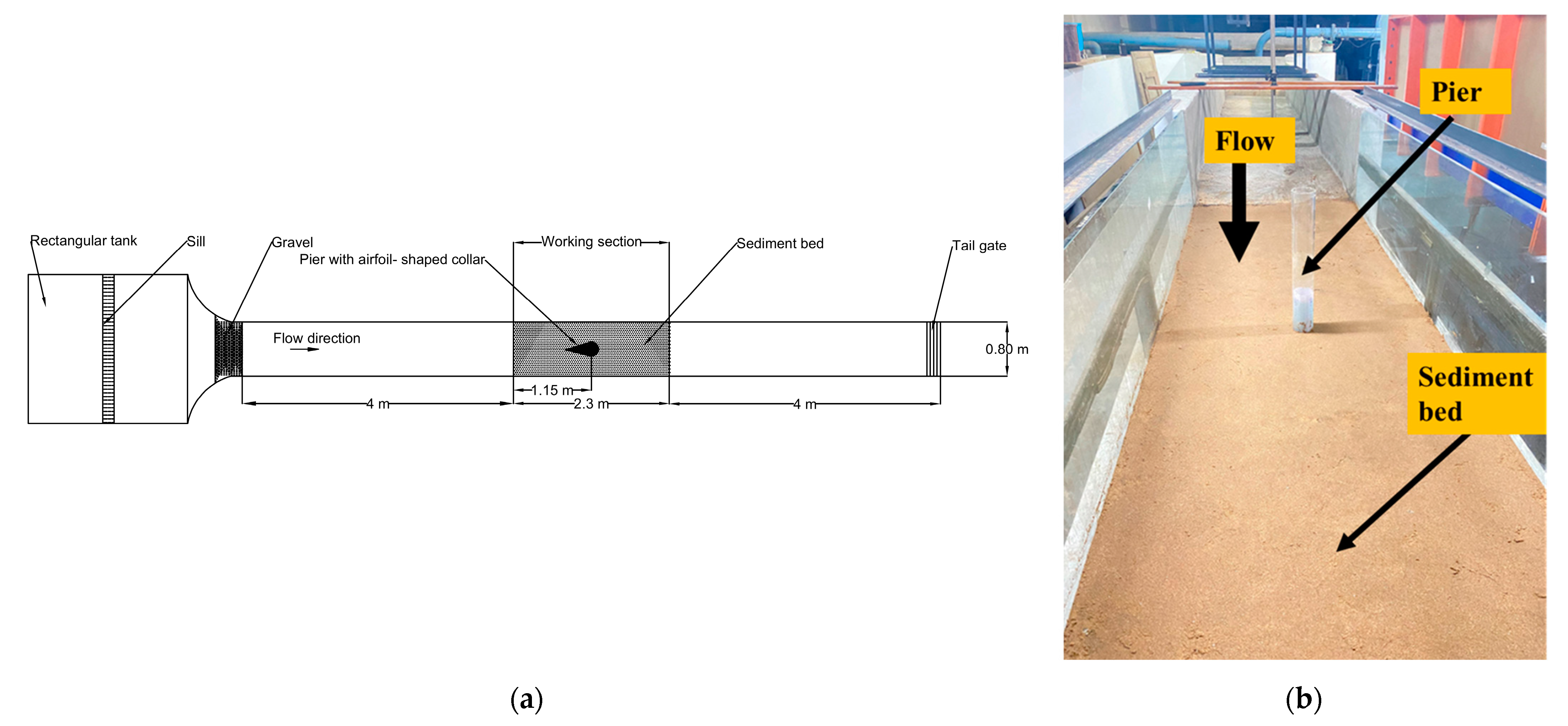
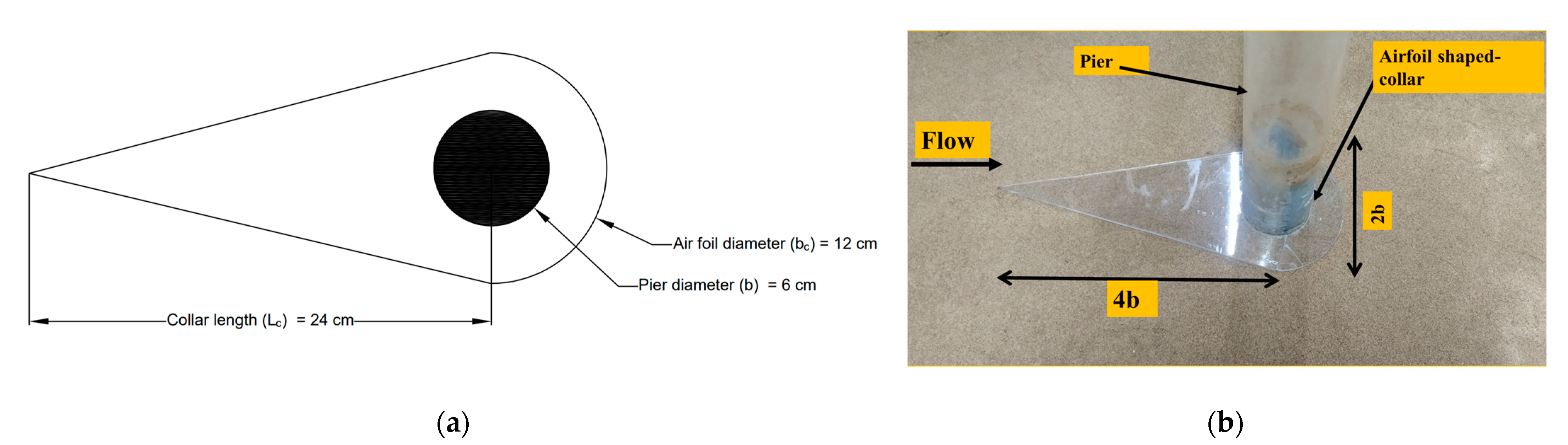
3. Experimental Setup and Materials

The experiments are conducted in the Fluid Mechanics Laboratory of the Civil Engineering Department at NIT Warangal, Telangana, India. The flume is 15.3 m in length, 0.8 m in width and 0.4 m in depth. The flume has a working section of 2.3 × 0.8 × 0.4 m located at 7 m from the upstream side of the channel. The working section has a side wall of glass to visualize the flow and scour processes around the pier. The maximum flow rate through this channel is 0.055 m3/s with a pump capacity of 11.19 kW. The flow rate is measured using the ultrasonic flow meter with an accuracy of ± 1%. The tailwater gate is fixed downstream of the flume to maintain constant flow depth in the flume. The present study uses fine sediment of medium size ( d 50 ) of 0.32 mm with a standard deviation (σ = d 84 / d 16 ) of 1.31, where d 84 and d 16 are the particle size at 84% and 16% finer, respectively. The pier diameter (b) of 6 cm is placed perpendicular to the flow direction and at the center of the working section. A digital point gauge with an accuracy of ±0.1 mm is used to measure the temporal and equilibrium scour depth around the pier. The layout of the working section is shown in Figure 1.

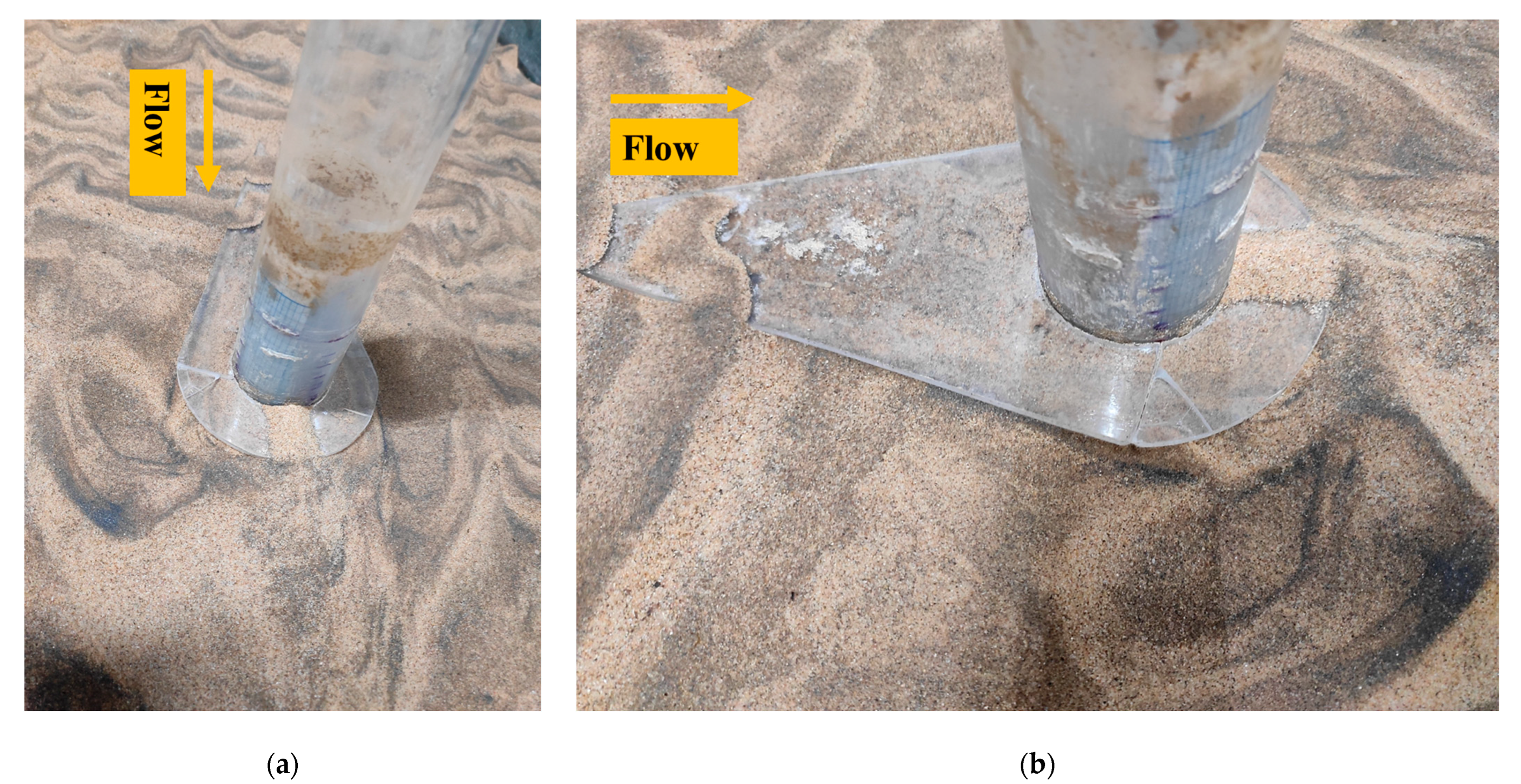
3.1. Description of Airfoil-Shaped Collar

Authors have used an airfoil-shaped collar as a scour countermeasure. It is fabricated by joining a triangle and a half circle of different diameters, as can be seen in Figure 2a,b. It is simply a flat horizontal disk that is mounted around a bridge pier to impede the downward flow along the front face of the pier. It is joined with a half circle to a triangle in an airfoil shape so that it becomes easy to construct on the field. The study uses four different airfoil-shaped collars made of acrylic material. The airfoil-shaped collar has four different diameters, i.e., b c 1 = 1.5 b , b c 2 = 2.0 b , b c 3 = 2.5 b and b c 4 = 3.0 b , where b is the diameter of the pier. The chord length of the collar ( L c ) is two times of collar diameter ( b c ). To avoid the contraction effect, the ratio of collar diameter to the channel width is kept around 0.20 [34,35]. The thickness of collar possesses the most negligible possible thickness, but in this case, it is kept at 4 mm. The airfoil-shaped collars are placed at four locations, i.e., bed level, y/4, y/2, and 3y/4, where y is the depth of flow, which is kept constant (10 cm) throughout the experimental runs. Figure 2b shows a sketch of the pier with collar in the experimental setup.

3.2. Hydraulic Conditions for Experiments

All the experimental runs are conducted under clear water conditions, i.e., V / V c < 1, where V is approach flow velocity, and V c is critical flow velocity of sediment entrainment. The approach flow velocity ( V ) is calculated using an ultrasonic flowmeter with an accuracy of ±1%, and V c is calculated using Equation (4) [1,36].
V c V * c = 5.75   log 5.53   y d 50
where V * c is critical shear velocity, which is calculated by the Shields curve. The experiments are conducted for two cases. All experiments are conducted with constant flow intensity, Reynolds number and Froude number having values 0.96, 0.252 and 14,976, respectively, as shown in Table 1. Case I represents the experimental run without airfoil- shaped collar, and Case II represents the experimental run with airfoil-shaped collar.

4. Results and Discussion

The following Table 2 and Table 3 show experimental outcomes with and without airfoil-shaped collar, respectively. If the change in scour depth is less than 0.05b in 24 h, then it is defined as equilibrium scour depth, as mentioned in Table 2 and Table 3 [1].

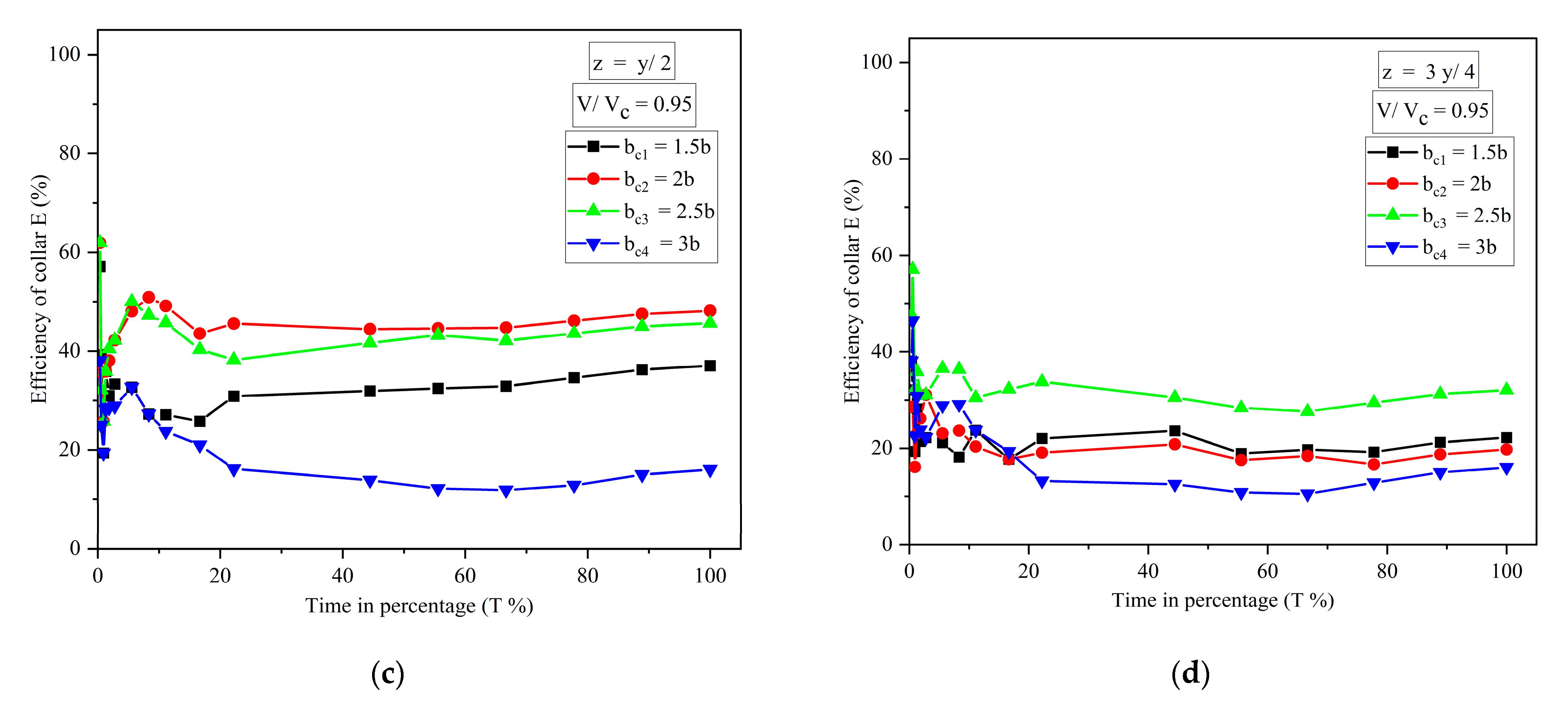
4.1. Temporal Variation of Scour Depth with and without Airfoil-Shaped Collars

The temporal variation of scour depth around the pier for four different collars at various locations is shown in Figure 3. Equilibrium scour depth of 10, 15 and 20% is reached at 70, 75 and 81% of equilibrium time, respectively. The value of 100 × scour depth at any time t, d t /equilibrium scour depth, d e , is equal to 10% of equilibrium scour depth, then it is equilibrium scour depth of 10%, similarly for equilibrium scour depth of 15% and 20%. Figure 3 shows that the initial rate of scouring is more rapid, later increases gradually and finally remains constant. The equilibrium scour depth around the pier without airfoil-shaped collar is 8.1 cm and with b c 1 at various locations, i.e., on bed level, y/4, y/2 and 3y/4 cm above the bed level, it is 2.5, 3.8, 5.1 and 6.3 cm, respectively, as shown in Figure 3a. With b c 2 at various locations, i.e., on bed level, y/4, y/2 and 3y/4 cm above the bed level, equilibrium scour depth around the pier is 0.8, 3.3, 4.2 and 6.5 cm, respectively, as shown in Figure 3b. With b c 3 at various locations, i.e., on bed level, y/4, y/2 and 3y/4 cm above the bed level is 0, 3.1, 4.4 and 5.5 cm, respectively, as shown in Figure 3c. With b c 4 at various locations, i.e., on bed level, y/4, y/2 and 3y/4 cm above the bed level is 0, 3.5, 4.8 and 6.5 cm, respectively, as shown in Figure 3d. When the b c 2 is kept on the bed, there is almost zero scour for the first five hours (i.e., 45% of equilibrium time), and the equilibrium scour depth is 0.8 cm. It is observed that for collars b c 3 and b c 4 , when they are kept on bed level, scouring around the pier is zero.
The percentages of scour reduction using the four collars ( b c 1 , b c 2 , b c 3 and b c 4 ) at bed level are 46, 86, 100 and 100%, respectively. It is observed that there is no scour around the pier with b c 3 and b c 4 . The percentage of scour reduction when collars are kept at y/4 above the bed level is 53, 59, 61 and 56%. When the collars (i.e., b c 1 , b c 2 , b c 3 and b c 4 ) are kept at elevation of y/2 above the bed level, percentages of scour reduction are 37, 48.14, 45.67 and 16%, respectively, and when kept at 3y/4 above the bed level, the percentages of scour reduction are 22, 19.75, 32.01 and 16%, respectively. Therefore, it can be concluded that airfoil-shaped collars at bed level are the most efficient in scour reduction. Collars with diameter of b c 2 , b c 3 and b c 4 are most efficient, which reduces the scour from 86 to 100%. For b c 1 at bed level, scouring rate is initially low, due to protection around the pier. For collar b c 2 , scouring started after 45% of equilibrium time. As the collar diameter is increased, scour depth around the pier is reduced. As collar diameter increases from b c 1 to b c 4 , scour depth around the pier is reduced. But collar diameter and length come into encroachment, so it should be optimized and cost-effective for field application. Therefore, it can be concluded that collar diameter with b c 2 and b c 3 is the most efficient countermeasure for scour around the pier. Installing the airfoil-shaped collar at bed level greatly improved the collar performance and no scour was observed around the pier.
The equilibrium scour depth around the pier is shown in Figure 4 for the collar b c 2 after the experimental run. It is observed that scour in the direction of 0°, 180° of the pier is negligible, and for 90°, 270° it is 0.8 cm.

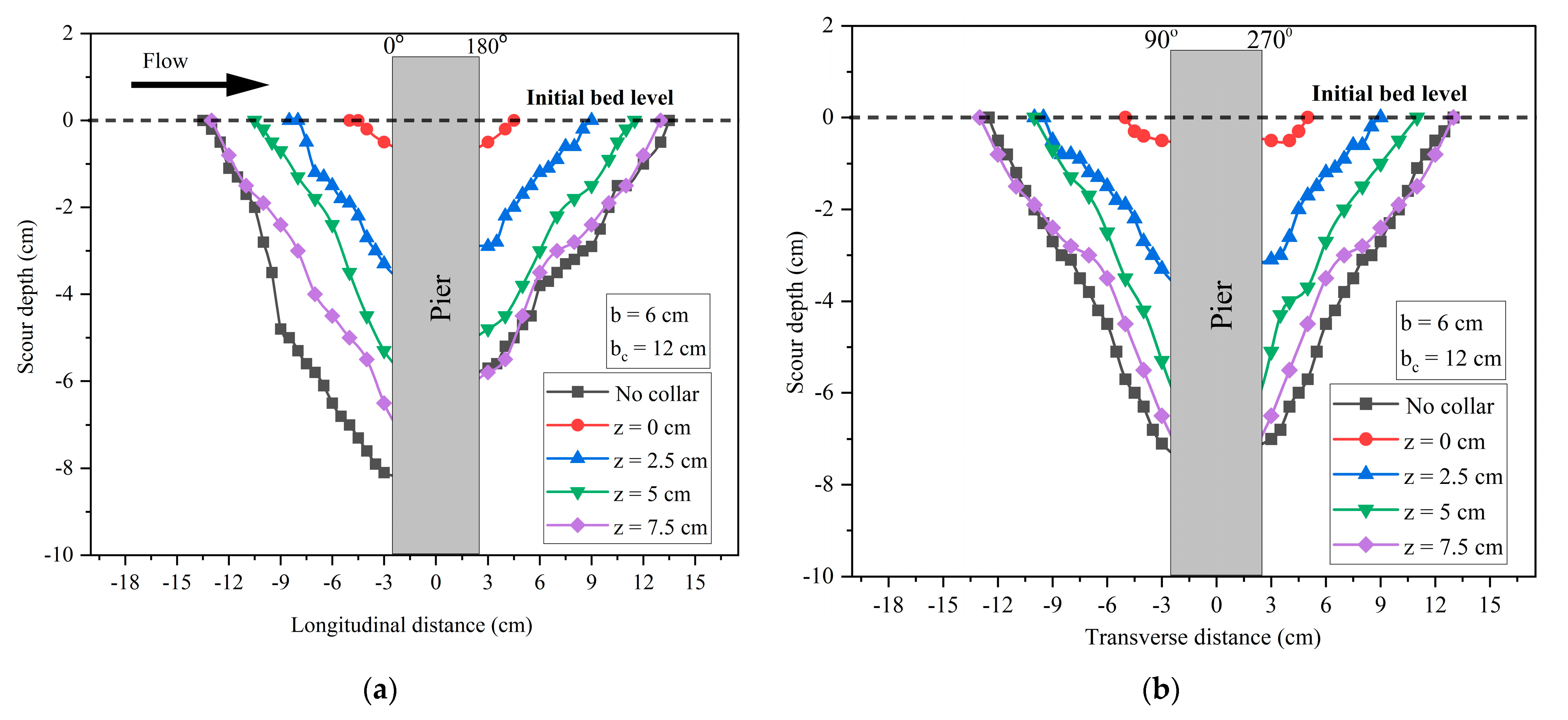
4.2. Scour Hole Profile with Airfoil-Shaped Collar

The transverse length of scour hole for the b c 2 at elevation on bed level, y/4, y/2 and 3y/4 above the bed level is 4.5, 13, 15 and 26 cm, respectively, as shown in Figure 5b. The scour hole length without the airfoil is 26 cm, which is the same as the case where the airfoil is kept 7.5 cm above bed level. The longitudinal and transverse scour length is varying from 24.5 and 26 cm, respectively. It is observed that the transverse length of the scour hole is greater than the longitudinal scour hole length.

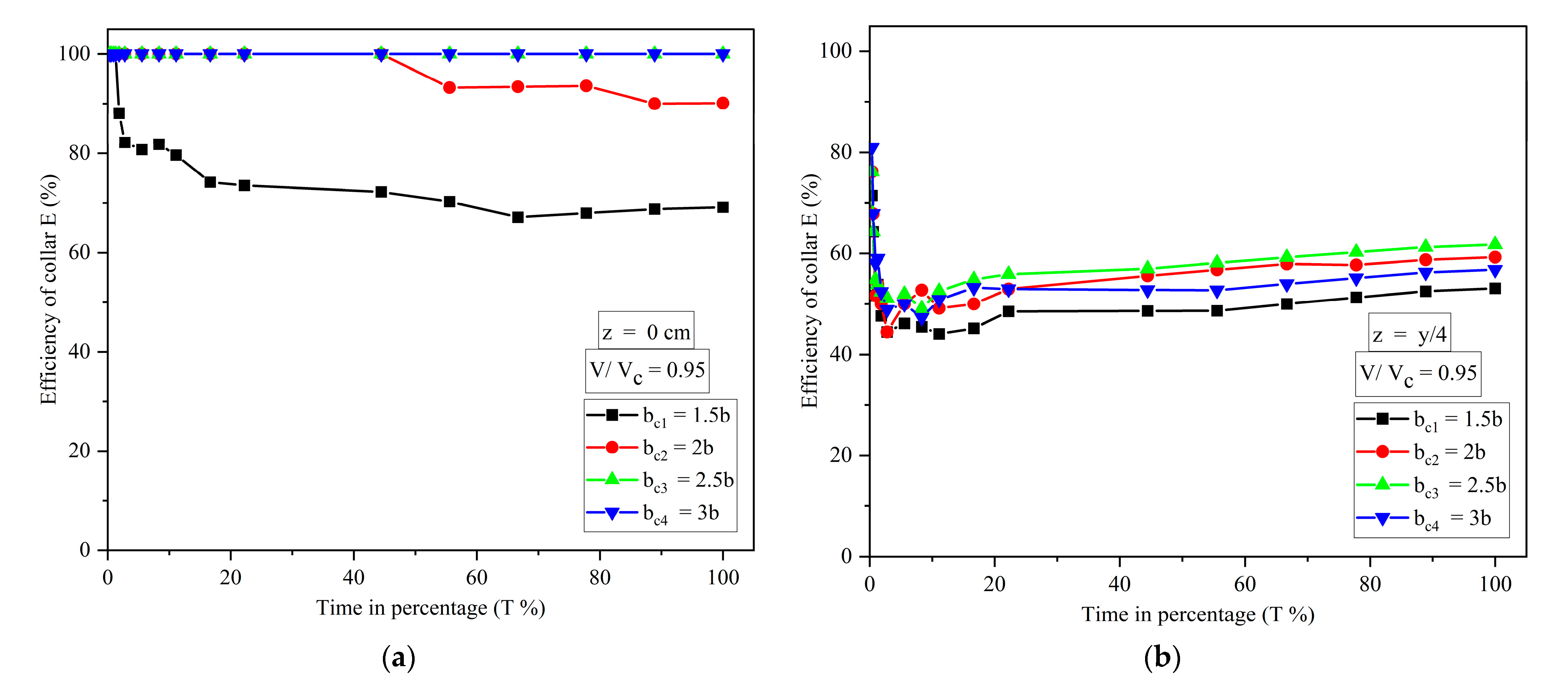
4.3. Efficiency of the Airfoil-Shaped Collar

The variation of the efficiency of collars with the percentage of time is shown in Figure 6. The efficiency of the collar is defined as:
E   % = d t d c t d t 100
where d t and d c t are scour depth around the pier without and with airfoil-shaped collar, respectively, at any time, t.
Figure 6a–d show scour reduction using a collar at different elevations in terms of efficiency at equilibrium scour, i.e., T = 100%. Figure 6a shows that the efficiency of collars b c 1 and b c 2 at bed level is 69.13% and 90.12%, respectively, and almost 100% for b c 3 and b c 4 . Figure 6b shows that the efficiency of collars b c 1 , b c 2 , b c 3 and b c 4 at the elevation y/4 above the bed level is 53.06, 59.26, 61.8 and 56.8%, respectively. Figure 6c shows that the efficiency of collars b c 1 , b c 2 , b c 3 and b c 4 is 37.1, 48.15, 45.6 and 16.05%, respectively, when placed at the elevation y/2 above the bed level. When the collars are placed at the elevation of 3y/4 above the bed level, efficiency of collars b c 1 , b c 2 , b c 3 and b c 4 is 22.22, 19.75, 32.1 and 16.05%, respectively, as shown in Figure 6d. For all the elevations, it is observed that the maximum reduction of scour is found for Figure 6a, i.e., collar elevation at bed level, and the efficiency of the collar increases with an increase in collar diameter. However, it is the same for b c 3 and b c 4 for the case of the collar’s elevation at bed level. For all the elevations of the collar, the efficiency of the collar almost increases with an increase in collar diameters, as can be seen in Figure 6a–d. Collar b c 3 is efficient in scour reduction when placed at y/4 and 3y/4 above the bed level, and collar b c 2 is efficient when placed at y/2 above the bed level. From Figure 6a–d, it is observed that there is a decrement in the collar’s efficiency initially. Due to the protection provided by the collar around the pier, the efficiency of the collar increases with respect to time and becomes almost constant in the final stages. In addition, collars delay the scour process and scour hole development at the perimeter of the pier.

5. Numerical Simulation

Computational fluid dynamics (CFD) is an important tool for implementing numerical simulations for studying the natural currents in water bodies with fine materials. Experimental studies incur more cost, time, human resources, restrictions and data collection problems and only permits data to be extracted from limited locations. Additionally, data extraction can be performed only from the locations where gauges and sensors are installed. On the other hand, a wide range of hydrodynamic fluid flows and robust numerical simulation modelling can be performed using CFD and it allows for examination of any location in the region of interest [19,37,38,39,40,41,42,43]. It can theoretically simulate any physical condition and allow the study of a specific isolated phenomenon. Enhancement in computational capabilities made the application of numerical methods easier in sediment transport for computations of scour around hydraulic structures. The simulation study is carried out with the help of the CFD software FLOW-3D. It solves the non-linear Navier–Stokes equation for three-dimensional flow while tracking the water surface using the volume of fluid (VOF) model. The filtered Navier–Stokes equations include the filtered continuity and momentum equations. These equations compute both the mean flow and large eddies. The study uses the large eddy simulation (LES) method as a turbulence model, which decomposes the instantaneous variables (velocity and pressure) into filtered (resolved) and sub-filtered (unresolved or residual) variables. Here, velocity is used as an example.
u i = u ¯ i + u i
where u i , u ¯ i and u i are instantaneous, filtered and sub-filtered velocities, respectively. LES method as a turbulence model is shown below:
ρ t + ρ u ¯ i x i = 0
u ¯ i t + u ¯ j u ¯ i x j = 1 ρ   p ¯ x i + x j   ν u ¯ i x j + 1 ρ   τ i j x j
τ i j   = u ¯ i u ¯ j u i u j ¯
where ρ is fluid density, t is time, u ¯ i is the i-th component of filtered velocities, x j is cartesian coordinates, p ¯ is filtered pressure, ν is kinematic viscosity, and τ i j is subgrid-scale (SGS) stress [36,37]. The van Rijn equation, as a sediment transport equation, evaluates the dimensionless rate of bed-load transport [38].
Φ = β   D * 0.3 θ θ c r 1.0 2.1 C b
where ϕ is dimensionless rate of bed-load transport, β is bed load coefficient, D * is dimensionless particle size, θ and θ c r are local and critical Shields parameters, respectively, and C b is sediment fraction volume.
Simulation setup and sediment particle properties are carried out similarly to the experimental study. The simulation uses a nested mesh configuration with the Cartesian coordinate system. The total number of mesh cells is 5.4 million, and coarse and fine mesh are 1.8 and 3.6 million, respectively. This is accomplished in FLOW-3D by considering the suspended and packed states of the sediment. In FLOW-3D, VOF represents fluid behavior on a free surface, whereas fractional area–volume obstacle representation (FAVOR) represents surfaces and complex geometric boundaries [44]. Figure 7 shows the favorized geometry images of sediment bed and pier with collar in the simulation set. The input boundary condition for upstream, downstream, floor, lateral side and free surface are velocity, continuative, wall, wall and symmetry, respectively. Velocity is applied as flow input and continuative as outflow boundary condition, which represents the smooth continuation of flow. Wall boundary condition is virtually frictionless behavior of the bed and sides of the channel, while symmetry boundary condition is inviscid property of the wall.

5.1. Simulation Results

The scour around the pier without airfoil-shaped collar is 9.2 cm from the FLOW-3D simulation result. It is an error of equilibrium scour depth by 11% with the experimental result. The difference between experimental and simulation results is due to the simplification of the complexity of the flow, vortices and real-world factors.
Figure 8 shows the dimensionless scour depth vs. dimensionless time diagram for pier without airfoil-shaped collar in observed and numerical simulation, where d t and d e are scour depth at any time t and equilibrium time (T). It shows that the dimensionless scour from the simulation results is underestimated. The value of the coefficient of correlation between numerical and observed models is 0.92.

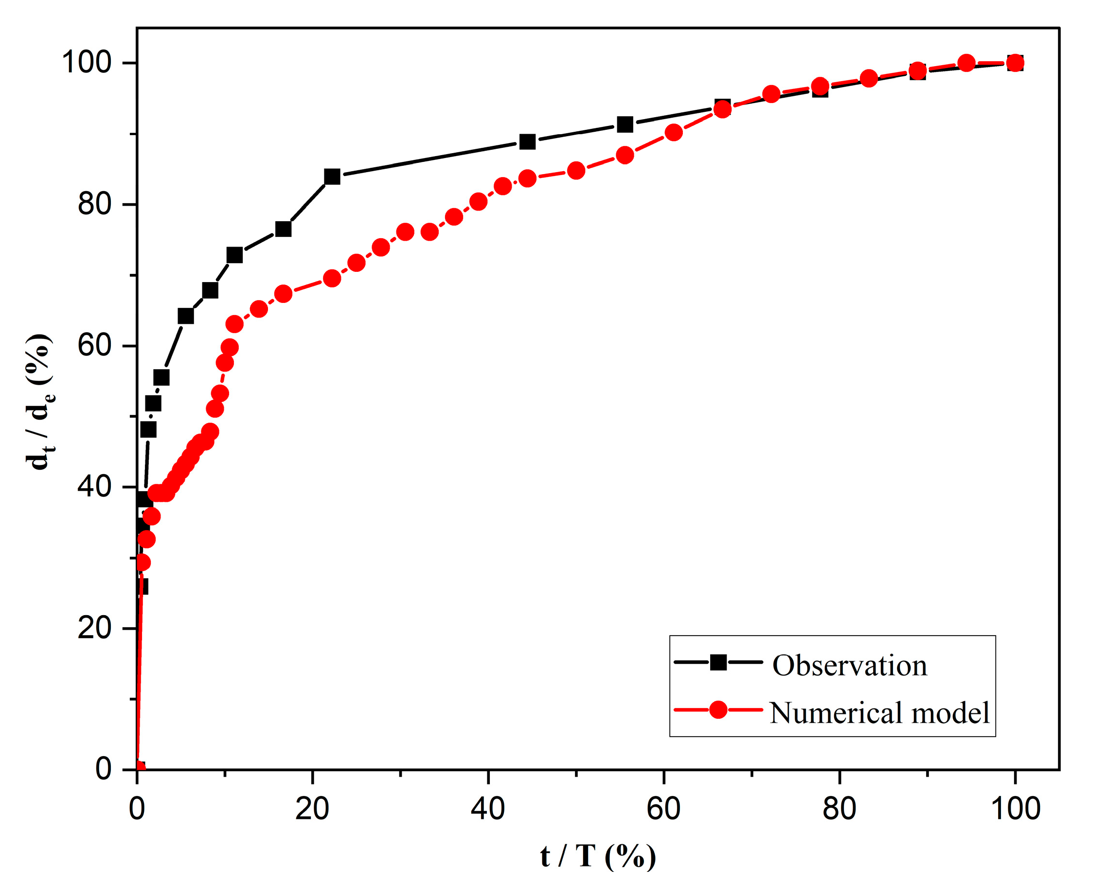
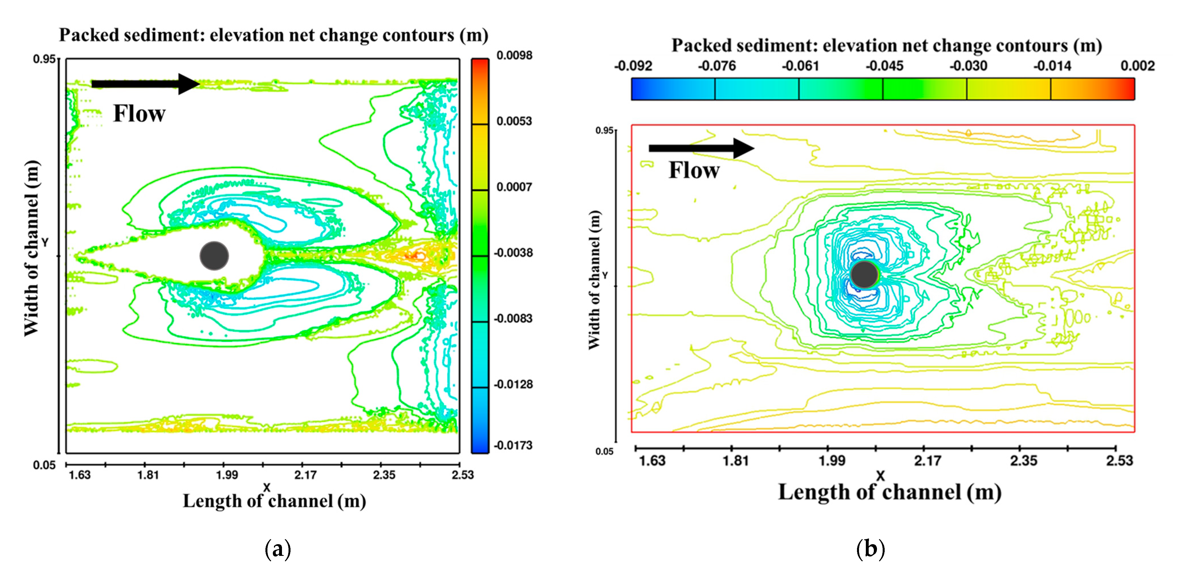
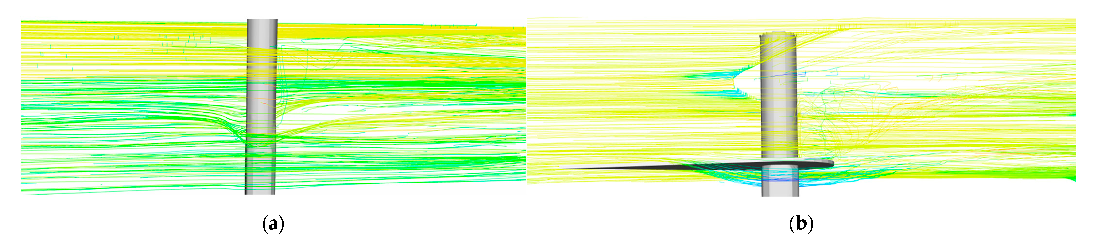
5.2. Morphological Changes, Scour Depth Contour and Streamlines Pattern

The scour depth around the pier is shown in Figure 9. It is observed that scour around airfoil-shaped collar b c 4 is 1.6 cm and around the pier, it is zero, when airfoil-shaped collar is placed at bed level. Figure 10 shows contour scour depth changes around the pier with and without a collar b c 4 , and it is observed that no scour occurred around the pier. Figure 11 shows that flow velocity in the wake regions behind the pier is very small, while maximum flow velocity is observed at the side of the pier. For the pier with collar b c 4 , gradual flow separation is observed, avoiding sudden flow separation. Zero velocity streamlines are more in number around the pier in the presence of a collar, which implies the reduction in intensity of horseshoe and wake vortices.

6. Conclusions

This paper investigates the airfoil-shaped collar as scour countermeasure around the bridge pier by conducting laboratory experiments and numerical simulation using FLOW-3D. The airfoil-shaped collar weakens the horseshoe and wake vortices. As a result, the scour depth reduces in front of the pier. The temporal variation of scour depth for four different airfoil-shaped collars when placed at four elevations, i.e., bed level, y/2, y/2 and 3y/4 above the bed level are presented. The following are the conclusions that can be drawn from this study.
The percentages of scour reduction using the four collars ( b c 1 , b c 2 , b c 3 and b c 4 ) at bed level are 46, 86, 100 and 100%, respectively. It is observed that there is no scour around the pier with b c 3 and b c 4 . The percentage of scour reduction when collars are kept at y/4 above the bed level is 53, 59, 61 and 56%. When the collars (i.e., b c 1 , b c 2 , b c 3 and b c 4 ) are kept at elevation of y/2 above the bed level, percentages of scour reduction are 37, 48.14, 45.67 and 16%, respectively, and when kept at 3y/4 above the bed level, the percentages of scour reduction are 22, 19.75, 32.01 and 16%, respectively.
For b c 1 at bed level, the scouring rate is initially low, due to protection around the pier. For collar b c 2 , scouring started after 45% of equilibrium time. As the collar diameter is increased, scour depth around the pier is reduced. Collar diameters with b c 3 and b c 4 are the most efficient countermeasures for scour around the pier due to the longitudinal length and diameter of the collars protecting the perimeter of the pier. Installing the airfoil shaped collar at bed level greatly improved the collar performance and no scour was observed around the pier. Initially, efficiency of the collar is reduced rapidly due to the rapid rate of scouring around the pier.
The efficiency of the collar increases later, due to the weakening of the horseshoe vortex and the protection provided by the airfoil-shaped collar. It is observed that the transverse length of the scour hole is greater than the longitudinal scour hole length. Error between the experimental and simulation results is 11% for pier without airfoil-shaped collar. It is validated that there is no scour around the pier with b c 4 placed on the bed in both experiment and simulation. Morphological changes, scour depth contours and streamlines are plotted for pier with and without collar b c 4 .

Author Contributions

Conceptualization, M.P. and P.A.R.; methodology, L.K.G. and M.P.; software, L.K.G.; validation, M.P., L.K.G. and J.H.P.; formal analysis, L.K.G.; investigation, M.P., L.K.G. and J.H.P.; resources, M.P. and L.K.G.; data curation, L.K.G.; writing—original draft preparation, L.K.G.; writing—review and editing, M.P., L.K.G. and J.H.P.; visualization, M.P. and P.A.R.; funding acquisition, P.A.R. All authors have read and agreed to the published version of the manuscript.

Funding

This research received no external funding.

Institutional Review Board Statement

Not applicable.

Informed Consent Statement

Not applicable.

Data Availability Statement

All used data are available in the manuscript.

Acknowledgments

Authors thank the anonymous reviewers.

Conflicts of Interest

The authors declare no conflict of interest.

References

  1. Melville, B.W.; Chiew, Y. Time Scale For Local Scour At Bridge Piers. J. Hydraul. Eng. 1999, 125, 59–65. [Google Scholar] [CrossRef]
  2. Kothyari, U.C.; Kumar, A. Temporal Variation of Scour around Circular Compound Piers. J. Hydraul. Eng. 2012, 138, 945–957. [Google Scholar] [CrossRef]
  3. Negm, A.M.; Moustafa, G.M.; Abdalla, Y.M.; Fathy, A.A.; Affairs, S. Optimal Shape of Collar To Minimize Local Scour Around Bridge Piers. In Proceedings of the Thirteenth International Water Technology Conferenc, IWTC13 2009, Hurghada, Egypt, 12–15 March 2009; pp. 1–13. [Google Scholar]
  4. Lagasse, P.F.; Clopper, P.E.; Zevenbergen, L.W.; Girard, L.G. Countermeasures to Protect Bridge Piers from Scour; NCHRP: Washington, DC, USA, 2007; ISBN 9780309099097. [Google Scholar]
  5. Deng, L.; Wang, W.; Yu, Y. State-of-the-Art Review on the Causes and Mechanisms of Bridge Collapse. J. Perform. Constr. Facil. 2016, 30, 04015005. [Google Scholar] [CrossRef]
  6. Gupta, L.K.; Pandey, M.; Raj, P.A.; Shukla, A.K. Fine Sediment Intrusion and Its Consequences for River Ecosystems: A Review. J. Hazard. Toxic Radioact. Waste 2023, 27, 04022036. [Google Scholar] [CrossRef]
  7. Khaple, S.; Hanmaiahgari, P.R.; Gaudio, R.; Dey, S. Interference of an Upstream Pier on Local Scour at Downstream Piers. Acta Geophys. 2017, 65, 29–46. [Google Scholar] [CrossRef]
  8. Pandey, M.; Pu, J.H.; Pourshahbaz, H.; Khan, M.A. Reduction of Scour around Circular Piers Using Collars. J. Flood Risk Manag. 2022, 15, e12812. [Google Scholar] [CrossRef]
  9. Wang, S.; Wei, K.; Shen, Z.; Xiang, Q. Experimental Investigation of Local Scour Protection for Cylindrical Bridge Piers Using Anti-Scour Collars. Water 2019, 11, 1515. [Google Scholar] [CrossRef] [Green Version]
  10. Wardhana, K.; Hadipriono, F.C. Analysis of Recent Bridge Failures in the United States. J. Perform. Constr. Facil. 2003, 17, 144–150. [Google Scholar] [CrossRef] [Green Version]
  11. Hunt, B.E. NCHRP Synthesis 396: Monitoring Scour Critical Bridges—A Synthesis of Highway Practice; NCHRP: Washington, WA, USA, 2009; ISBN 9780309098342. [Google Scholar]
  12. Shahriar, A.R.; Ortiz, A.C.; Montoya, B.M.; Gabr, M.A. Bridge Pier Scour: An Overview of Factors Affecting the Phenomenon and Comparative Evaluation of Selected Models. Transp. Geotech. 2021, 28, 100549. [Google Scholar] [CrossRef]
  13. Prendergast, L.J.; Gavin, K. A Review of Bridge Scour Monitoring Techniques. J. Rock Mech. Geotech. Eng. 2014, 6, 138–149. [Google Scholar] [CrossRef]
  14. Mashahir, A.R.Z.M.N. and M.B. Reduction of Local Scour in the Vicinity of Bridge Pier Groups Using Collars and Riprap. XI Jorn. Españolas Presas 2006, 132, 154–162. [Google Scholar] [CrossRef]
  15. Dey, S.; Bose, S.K.; Sastry, G.L.N. Clear Water Scour at Circular Piers: A Model. J. Hydraul. Eng. 1995, 121, 869–876. [Google Scholar] [CrossRef]
  16. Zhang, H.; Nakagawa, H.; Mizutani, H. Bed Morphology and Grain Size Characteristics around a Spur Dyke. Int. J. Sediment Res. 2012, 27, 141–157. [Google Scholar] [CrossRef]
  17. Valela, C.; Nistor, I.; Rennie, C.D.; Lara, J.L.; Maza, M. Hybrid Modeling for Design of a Novel Bridge Pier Collar for Reducing Scour. J. Hydraul. Eng. 2021, 147, 04021012. [Google Scholar] [CrossRef]
  18. Christopher, V.; Loan, N.; Colin, R. Reduction of Bridge Pier Scour through the Use of a Novel Collar Design. In Proceedings of the Canadian Society for Civil Engineering, Fredericton, NB, Canada, 13–16 June 2018; pp. 235–244. [Google Scholar]
  19. Gazi, A.H.; Purkayastha, S.; Afzal, M.S. The Equilibrium Scour Depth around a Pier under the Action of Collinearwaves and Current. J. Mar. Sci. Eng. 2020, 8, 36. [Google Scholar] [CrossRef] [Green Version]
  20. Ahmad, N.; Bihs, H.; Afzal, M.S.; Arntsen, Ø.A. Three-Dimensional Numerical Modeling of Local Scour Around a Non-Slender Cylinder Under Varying Wave Conditions. In Proceedings of the 36th IAHR World Congress, Hague, The Netherlands, 28 June–3 July 2015; pp. 1–14. [Google Scholar]
  21. Ghodsi, H.; Najafzadeh, M.; Khanjani, M.J.; Beheshti, A. Effects of Different Geometric Parameters of Complex Bridge Piers on Maximum Scour Depth: Experimental Study. J. Waterw. Port, Coastal, Ocean Eng. 2021, 147, 1–15. [Google Scholar] [CrossRef]
  22. Najafzadeh, M.; Barani, G.A. Experimental Study of Local Scour around a Vertical Pier in Cohesive Soils. Sci. Iran. 2014, 21, 241–250. [Google Scholar]
  23. Kumar, V.; Raju, K.G.R.; Vittal, N. Reduction of Local Scour Around Bridge Piers Using Slots and Collars. J. Hydraul. Eng. 1999, 125, 1302–1305. [Google Scholar] [CrossRef]
  24. Chiew, Y. Scour Protection at Bridge Piers. J. Hydraul. Eng. 1992, 118, 1260–1269. [Google Scholar] [CrossRef]
  25. Zarrati, A.R.; Gholami, H.; Mashahir, M.B. Application de Collier Pour Contrôler l’affouillement Autour Des Piles de Pont Rectangulaires. J. Hydraul. Res. 2004, 42, 97–103. [Google Scholar] [CrossRef]
  26. Chen, S.C.; Tfwala, S.; Wu, T.Y.; Chan, H.C.; Chou, H. Ter A Hooked-Collar for Bridge Piers Protection: Flow Fields and Scour. Water 2018, 10, 1251. [Google Scholar] [CrossRef] [Green Version]
  27. Khodashenas, S.R.; Shariati, H.; Esmaeeli, K. Comparison between the Circular and Square Collar in Reduction of Local Scouring around Bridge Piers. E3S Web Conf. 2018, 40, 03002. [Google Scholar] [CrossRef]
  28. Pandey, M.; Azamathulla, H.M.; Chaudhuri, S.; Pu, J.H.; Pourshahbaz, H. Reduction of Time-Dependent Scour around Piers Using Collars. Ocean Eng. 2020, 213, 107692. [Google Scholar] [CrossRef]
  29. Moncada-M, A.T.; Aguirre-Pe, J.; Bolívar, J.C.; Flores, E.J. Scour Protection of Circular Bridge Piers with Collars and Slots. J. Hydraul. Res. 2009, 47, 119–126. [Google Scholar] [CrossRef]
  30. Masjedi, A.; Bejestan, M.S.; Esfandi, A. Reduction of Local Scour at a Bridge Pier Fitted with a Collar in a 180 Degree Flume Bend (Case Study: Oblong Pier). J. Hydrodyn. 2010, 22, 669–673. [Google Scholar] [CrossRef]
  31. Tafarojnoruz, A.; Gaudio, R.; Calomino, F. Evaluation of Flow-Altering Countermeasures against Bridge Pier Scour. J. Hydraul. Eng. 2012, 138, 297–305. [Google Scholar] [CrossRef]
  32. Salamatian, M.; Zarrati, A.R.; Zokaei, S.A.; Karimaee, M. Study on Scouring around Bridge Piers Protected by Collar Using Low Density Sediment. Int. J. Civ. Eng. 2013, 11, 199–205. [Google Scholar]
  33. Tabarestani, M.K.; Zarrati, A.R. Local Scour Depth at a Bridge Pier Protected by a Collar in Steady and Unsteady Flow. Proc. Inst. Civ. Eng. Water Manag. 2019, 172, 301–311. [Google Scholar] [CrossRef]
  34. Kothyari, U.C.; Hager, W.H.; Oliveto, G. Generalized Approach for Clear-Water Scour at Bridge Foundation Elements. J. Hydraul. Eng. 2007, 133, 1229–1240. [Google Scholar] [CrossRef]
  35. Singh, R.K.; Pandey, M.; Pu, J.H.; Pasupuleti, S.; Villuri, V.G.K. Experimental Study of Clear-Water Contraction Scour. Water Sci. Technol. Water Supply 2020, 20, 943–952. [Google Scholar] [CrossRef]
  36. Melville, B.W. Pier and Abutment Scour: Integrated Approach. J. Hydraul. Eng. 1997, 123, 125–136. [Google Scholar] [CrossRef]
  37. Pourshahbaz, H.; Abbasi, S.; Pandey, M.; Pu, J.H.; Taghvaei, P.; Tofangdar, N. Morphology and Hydrodynamics Numerical Simulation around Groynes. ISH J. Hydraul. Eng. 2022, 28, 53–61. [Google Scholar] [CrossRef]
  38. Giglou, A.N.; Mccorquodale, J.A.; Solari, L. Numerical Study on the Effect of the Spur Dikes on Sedimentation Pattern. Ain Shams Eng. J. 2018, 9, 2057–2066. [Google Scholar] [CrossRef]
  39. Choufu, L.; Abbasi, S.; Pourshahbaz, H.; Taghvaei, P.; Tfwala, S. Investigation of Flow, Erosion, and Sedimentation Pattern around Varied Groynes under Different Hydraulic and Geometric Conditions: A Numerical Study. Water 2019, 11, 235. [Google Scholar] [CrossRef] [Green Version]
  40. Gautam, S.; Dutta, D.; Bihs, H.; Afzal, M.S. Three-Dimensional Computational Fluid Dynamics Modelling of Scour around a Single Pile Due to Combined Action of the Waves and Current Using Level-Set Method. Coast. Eng. 2021, 170, 104002. [Google Scholar] [CrossRef]
  41. Kirkil, G.; Constantinescu, G.; Ettema, R. Detached Eddy Simulation Investigation of Turbulence at a Circular Pier with Scour Hole. J. Hydraul. Eng. 2009, 135, 888–901. [Google Scholar] [CrossRef]
  42. Zhiyin, Y. Large-Eddy Simulation: Past, Present and the Future. Chin. J. Aeronaut. 2015, 28, 11–24. [Google Scholar] [CrossRef] [Green Version]
  43. van Rijn, L.C. Mathematical Modelling of Morphological Processes in the Case of Suspended Sediment Transport; Waterloopkundig Laboratorium: Delft, The Netherlands, 1987. [Google Scholar]
  44. Flow Science, I. Flow-3d User Manual; V11.2.; Flow Science: Santa Fe, NM, USA, 2016. [Google Scholar]
Figure 1. (a) Experimental setup in line diagram (plan view); (b) working section of the flume used in experiments.
Hydrology 10 00077 g001
Figure 2. Description of airfoil-shaped collar b c 2 : (a) sketch of b c 2 ; (b) collar b c 2 used in the experiment.
Hydrology 10 00077 g002
Figure 3. Temporal variation of scour depth around the pier with and without four different collars: (a) for collar b c 1 ; (b) for collar b c 2 ; (c) for collar b c 3 ; (d) for collar b c 4 .
Hydrology 10 00077 g003
Figure 4. Equilibrium scour depth around the pier with airfoil-shaped collar of diameter of b c 2 at bed level: (a) rear view; (b) side view.
Hydrology 10 00077 g004
Figure 5. Scour hole profile for collar b c 2 : (a) longitudinal; (b) transverse profile.
Hydrology 10 00077 g005
Figure 6. The variation of efficiency of collars with the percentage of time: (a) at bed level; (b) y/4 above the bed level; (c) y/2 above the bed level; and (d) 3y/4 above the bed level.
Hydrology 10 00077 g006aHydrology 10 00077 g006b
Figure 7. Favorized geometry images of the simulation set: (a) sediment bed, pier and airfoil-shaped collar; (b) pier with airfoil-shaped collar ( b c 4 ).
Hydrology 10 00077 g007
Figure 8. Dimensionless scour depth vs. dimensionless time diagram for observed and numerical model.
Hydrology 10 00077 g008
Figure 9. Visualization of morphological changes in the sediment bed: (a) with the favorized surface; (b) with color scale of fraction of fluid surface.
Hydrology 10 00077 g009
Figure 10. Contours of net elevation change in sediment bed: (a) with airfoil-shaped collar; (b) without collar.
Hydrology 10 00077 g010
Figure 11. Streamlines pattern around: (a) pier without collar; (b)pier with collar b c 4 on bed.
Hydrology 10 00077 g011
Table 1. Flow and sediment bed parameters.
Medium Size of Particles, d50 (mm)Flow Depth, y (cm)Flow Intensity ( V / V c ) Reynolds NumberFroude Number
0.32100.9514,9760.252
Table 2. Experimental outcome without airfoil-shaped collar.
Experimental RunsMedium Size of Particles, d50 (mm)Diameter of Pier, b (cm)Width of the Channel, B (m)Equilibrium Scour around the Pier, de (cm)
ER 10.3260.88.1
Table 3. Experimental outcomes with airfoil-shaped collar.
Experimental Runs with the CollarMedium Size of Particles, d50 (mm)Diameter of Pier, b (cm)Diameter of Collar, bc (cm)Length of Collar, LcCollar Locations, z (cm)Equilibrium Scour around the Pier with Collar, dce (cm)
ERC10.32691802.5
ERC20.3269182.53.8
ERC30.32691855.1
ERC40.3269187.56.3
ERC50.326122400.8
ERC60.32612242.53.3
ERC70.326122454.2
ERC80.32612247.56.5
ERC90.326153000
ERC100.32615302.53.1
ERC110.326153054.4
ERC120.32615307.55.5
ERC130.326183600
ERC140.32618362.53.5
ERC150.326183654.8
ERC160.32618367.55.5
Disclaimer/Publisher’s Note: The statements, opinions and data contained in all publications are solely those of the individual author(s) and contributor(s) and not of MDPI and/or the editor(s). MDPI and/or the editor(s) disclaim responsibility for any injury to people or property resulting from any ideas, methods, instructions or products referred to in the content.

