Article

Simulation of Sorption-Enhanced Steam Methane Reforming over Ni-Based Catalyst in a Pressurized Dual Fluidized Bed Reactor

1
Institute of Combustion and Thermal Systems, School of Mechanical, Electronic and Control Engineering, Beijing Jiaotong University, Beijing 100044, China
2
Department of Energy Storage Science and Technology, University of Science and Technology Beijing, Beijing 100083, China
*
Authors to whom correspondence should be addressed.
Inorganics 2023, 11(3), 107; https://doi.org/10.3390/inorganics11030107
Submission received: 30 January 2023 / Revised: 2 March 2023 / Accepted: 2 March 2023 / Published: 5 March 2023
(This article belongs to the Special Issue Inorganics for Catalysts: Design, Synthesis and Applications)

Abstract

:
Steam methane reforming is a major method of hydrogen production. However, this method usually suffers from low energy efficiency and high carbon-emission intensity. To solve this issue, a novel steam-methane-reforming process over a Ni-based catalyst in a pressurized dual fluidized bed reactor is proposed in this work. A three-dimensional computational fluid dynamics (CFD) model for the complex physicochemical process was built to study the reforming characteristics. The model was first validated against the reported data in terms of hydrodynamics and reaction kinetics. Next, the performance of the proposed methane-steam-reforming process was predicted. It was found that the methane-conversion ratio was close to 100%. The mole fraction of H2 in the dry-yield syngas reached 98.8%, the cold gas efficiency reached 98.5%, and the carbon-capture rate reached 96.4%. It is believed that the proposed method can be used for methane reforming with high efficiency and low carbon intensity.

Graphical Abstract

1. Introduction

With the development of human society, the hydrogen economy is currently attracting significant interest [1]. Therefore, many technologies have been developed for hydrogen production [2]. For example, hydrogen can be produced from fossil fuels through methods such as the steam reforming of natural gas or other hydrocarbons [3], the partial oxidation and catalytic partial oxidation of hydrocarbons [4], autothermal reforming, which can generate heat in situ during reforming [5], and plasma reforming, which uses plasma to enhance and supply heat for endothermic reactions [6]. Moreover, hydrogen can also be generated from renewable resources through various methods, which include the following: hydrogen production from biomass gasification [7]; hydrogen production from the pyrolysis or copyrolysis of biomass [8]; hydrogen production by aqueous-phase reforming, which is used to process oxygenated hydrocarbons or carbohydrates from renewable biomass resources to produce hydrogen [9]; water electrolysis, which directly splits water into hydrogen and oxygen with electric power [10]; photoelectrolysis, which utilizes a photoelectrochemical light-collection system to drive the electrolysis of water [11]; and thermochemical water-splitting technology, which uses heat alone to decompose water into hydrogen and oxygen [12]. Of all the major hydrogen-production technologies, steam methane reforming (SMR) is the most important and covers more than 45% of the world’s hydrogen supply [13]. Thereby, as one popular research method, numerical simulations featuring SMR have been increasingly reported by researchers all over the world. Cherif [14] numerically studied the auto-thermal methane reforming process in a segmented dual bed and continuous dual bed over the catalyst at 900 °C and 14 bar. It was found that the methane conversion reached 63.7% and the hydrogen proportion in the yield gas reached 80.9%. Sadeghi and Molaei [15] simulated the SMR process in a fixed-bed reactor filled with a nickel-oxide catalyst. At an inlet pressure of 19.3 bar, an inlet temperature of 748 K, and a steam-to-carbon ratio of 7, the outlet mole fraction of the H2 reached 75.5%. Wang [16] studied the effects of catalyst arrangement on the SMR process at a temperature of about 800 K and a pressure of about 4 bar through numerical simulation. It was predicted that the methane conversion would reach 75% and that the H2 fraction in the yield gas would reach 77%. Chen [17] studied the SMR in a micro-fluidized bed over a nickel-based catalyst through experiments and a numerical simulation. It was found that the methane conversion reached 95% at 973 K and that the H2 mole fraction reached 50% in the wet syngas.
Although SMR has been widely used for H2 production, the traditional SMR technology suffers from two essential deficiencies. One is large energy demand, since the reforming is endothermic [18], and the other is huge carbon intensity, since CO2 is the major byproduct of SMR [19]. The former deficiency adversely affects SMR’s thermal efficiency and further affects the hydrogen-production economy. The latter deficiency can lead to carbon-emission penalties and further weaken the hydrogen-production economy. To solve these issues, calcium-sorption-enhanced SMR over a catalyst has been proposed by several researchers [20]. The mechanism is shown by R1–R3, and the overall reaction can be cast into R4, according to Hess’s law [21]. It can be seen that the sorption-enhanced SMR is exothermic, so there is no need to burn additional methane to supply heat for the SMR process. Moreover, because the produced CO2 is absorbed by CaO, the SMR can then be enhanced according to the principle of Le Chatelier [22], and the hydrogen concentration in the yield gas can be further improved. Powell [23] modeled the sorption-enhanced SMR process with Aspen Plus software. It was found that, at a pressure of 30 bar and a temperature of 973 K, the CH4 conversion reached 99% and the H2 mole fraction reached 97% in the yield syngas. Carlo [24] simulated sorption-enhanced SMR in a fluidized bed reactor with a Ni catalyst and dolomite as the bed material. It was found that the dry hydrogen mole fraction was over 93% at a temperature of 900 K, at ambient pressure. Fernandez [25] proposed a novel Ca/Cu looping process for hydrogen production for sorption-enhanced SMR. As the oxygen carrier, CuO was used, so that N2 could be separated from the air during combustion, and the CaO was used to absorb CO2 during the reforming process. It was found that the maximum H2 purity reached 95% in the dry syngas, and the methane conversion was higher than 90%, at an operating pressure of 3.5 Mpa, tan inlet-steam-to-carbon ratio of 6, and an operating temperature of 973 K. Giuliano [26] studied a NieCaO–mayenite combined-sorbent catalyst material for sorption-enhanced SMR. The material’s sorption capacity was measured in multicycle sorption/regeneration TGA tests. It was found that the material’s activity was stable and the H2 fraction reached 97% in the dry syngas. Nardo [27] studied the sorption-enhanced SMR process in a bubbling fluidized bed reactor using computational particle fluid dynamics software. First, the simulation model was validated against experimental data. Then the sorption-enhanced SMR in a bubbling fluidized bed was studied. The operating temperature was 650 °C, the operating pressure was 1 atm, and the steam-to-carbon ratio was 4. It was found that the H2 was higher than 80% in the dry syngas. The H2 mole fraction decreased and the CO2 mole fraction increased with the conversion of the bed material. Solsvik [28] studied the sorption-enhanced SMR process in a bubbling fluidized bed reactor with a one-dimensional dynamic model. The prediction of the one-dimensional model was compared with that of the two-dimensional model, and sensitivity analyses were implemented. It was found that the dry H2 mole fraction and CH4 conversion increased with the temperature increment when the temperature was lower than 900 K.
CH 4 + H 2 O CO + 3 H 2 206.2   kJ / kmol
CO + H 2 O CO 2 + H 2 41.2   kJ / kmol
CO 2 + CaO CaCO 3 178   kJ / kmol
CH 4 + 2 H 2 O + CaO 4 H 2 + CaCO 3 23   kJ / kmol
Although sorption-enhanced SMR can effectively solve the essential issues in traditional SMR technology, the new issue of CaO regeneration arises. This should be clearly addressed so that sorption-enhanced SMR can be commercially used. To solve this issue, a dual fluidized bed, including a bubbling fluidized bed reforming reactor (BFBRR) and a fast fluidized bed calcination reactor (FFBCR) is designed in this work. The schematic flow sheet of the dual fluidized bed reactor is shown in Figure 1a and the structure of the dual bed is shown in Figure 1b. The diameter and height of the FFBCR are 0.1 m and 2.0 m, respectively. The total height of the BFBRR is 2.0 m, consisting of a lower bed part and an upper freeboard part. These two parts are connected by a cone-shaped section. The diameter and height of the lower part of BFBRR are 0.13 m and 1.2 m, respectively. The diameter and height of the upper freeboard of BFBRR are 0.4 m and 0.3 m, respectively. The diameter and height of the cylinder section of the cyclone are 0.2 m and 0.2 m, respectively. The diameter of the small side of the cone section of the cyclone is 0.06 m. The total height of the cyclone is 0.4 m. High-temperature steam and methane are injected into the BFBRR, where the methane reforming reaction, the water–gas-shift reaction, and the carbonation reaction take place. High-temperature CO2 is injected into the FFBCR, where the calcination reaction takes place. Limestone and a Ni-based catalyst were chosen as the bed materials. Part of the CaO is converted to CaCO3 in the BFBRR after absorbing CO2 at a relatively low temperature, and circulates to the FFBCR to regenerate CaO in the high-temperature CO2 atmosphere. Because the steam-to-carbon ratio is usually high and the CO2 mole fraction in the BFBRR is relatively low, the reforming pressure is improved so that more CO2 can be absorbed. This technology promises to continuously produce pure H2 with little carbon emission.

2. Results and Discussion

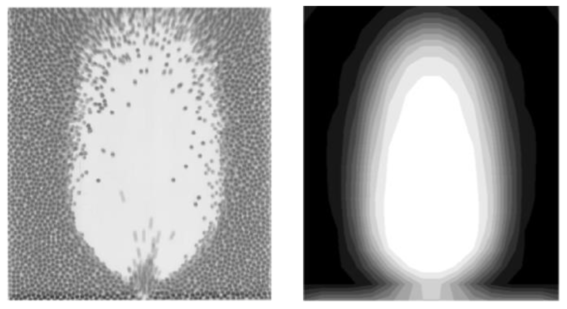
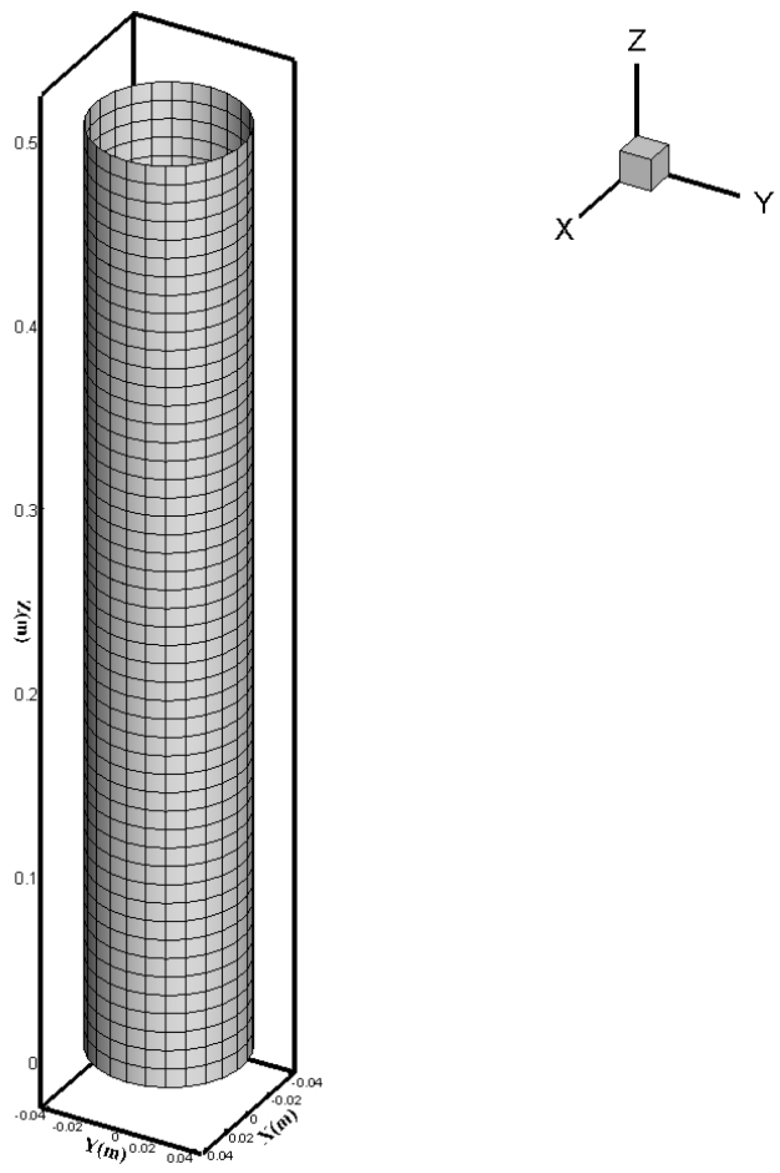
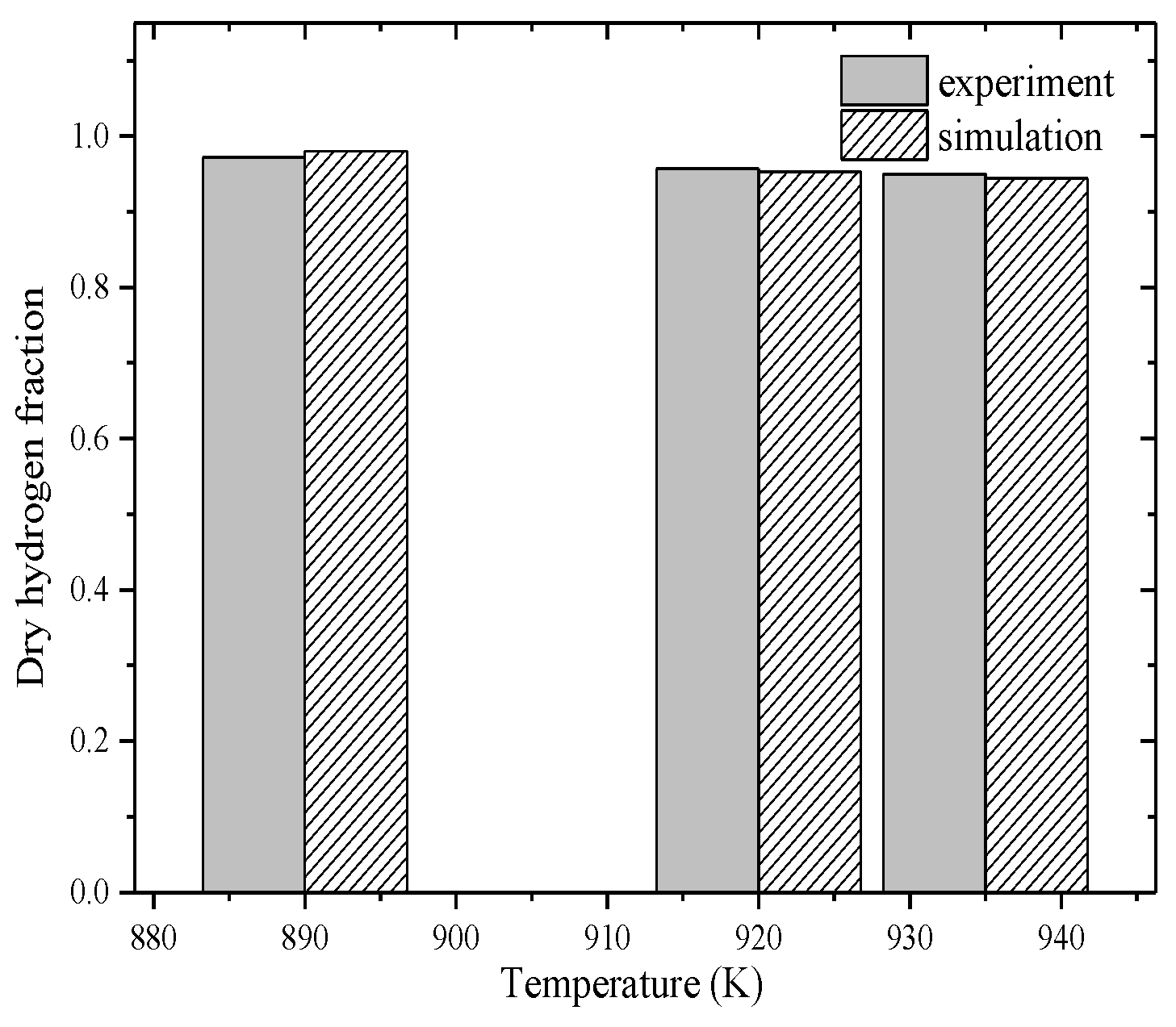
2.1. Model Validation

Before the numerical simulation model was used to conduct the prediction, the model needed to be validated. To validate the simulation methods used in this work for the hydrodynamic prediction, cold-mode experimental data were first used for comparison [29,30]. The experiment device was a cuboid box with a length of 0.15 m, a width of 0.015 m, and a height of 0.45 m. The bed material was silica sand with a diameter of 2.5 mm. The background velocity was 1.2 m/s. In the experiment, air was injected into the chamber through the bottom-center inlet at a velocity of 20 m/s. The injection lasted for 150 ms from the beginning, after which the bubble grew freely for the next 50 ms. The comparison between the model predictions and the experiment’s results is depicted in Figure 2. To validate the numerical simulation model for sorption-enhanced SMR, an experimental sorption-enhanced bubbling fluidized bed for SMR over a nickel-based catalyst was predicted with the model in this work. The reactor configuration is shown in Figure 3. The deionized water was pumped and vaporized at 463 K at a constant flow rate. The generated steam was then mixed with methane and heated to 823 K. Next, the gas mixture was fed to the reactor bed at 873–973 K. A cyclone and an anti-particulate filter were installed for particulate abatement. The syngas was finally cooled and dried in a water batch and a silica-gel-fixed bed. The superficial velocity was 0.45 m/s, the steam-to-carbon ratio was 4.0, the static bed height was 20 cm, the dolomite-to-catalyst volume ratio was 4.0, and the operating pressure was 1 atm. The reforming catalyst and CO2 absorption particles were mixed in the reformer. The catalyst was a commercial, nickel-based steam reforming catalyst ground to a mean particle diameter of 300 µm [24]. The comparison between the simulation predictions and the experiment data at different operation temperatures is shown in Figure 4.
In Figure 2, it is shown that the predicted flow pattern was close to the experimental pattern. Therefore, it is believed that the model used in this work can offer reliable hydrodynamic prediction for fluidized bed reactors. In Figure 3, it can be seen that the prediction agreed well with the experimental data at different temperatures. The relative errors between the predictions and experimental data at temperatures of 890 K, 920 K, and 935 K were 0.82%, 0.42%, and 0.63%, respectively. With the increase in temperature, the dry H2 mole fraction gradually decreased. This is because the water–gas-shift reaction was exothermic. At the appearance of the CaO, the water–gas-shift reaction can also be catalyzed and can reach an equilibrium state. According to the principle of Le Chatelier, this reaction can be restricted with the temperature increment, so the H2 mole fraction can be lowered. It should be noted that although this kind of reactor can generate H2 with high purity, the production process cannot last because the CaCO3 concentration in the bubbling fluidized bed can gradually increase and the CO2 sorption ability can gradually decrease with time. This is the reason why the dual fluidized bed is proposed in this work.

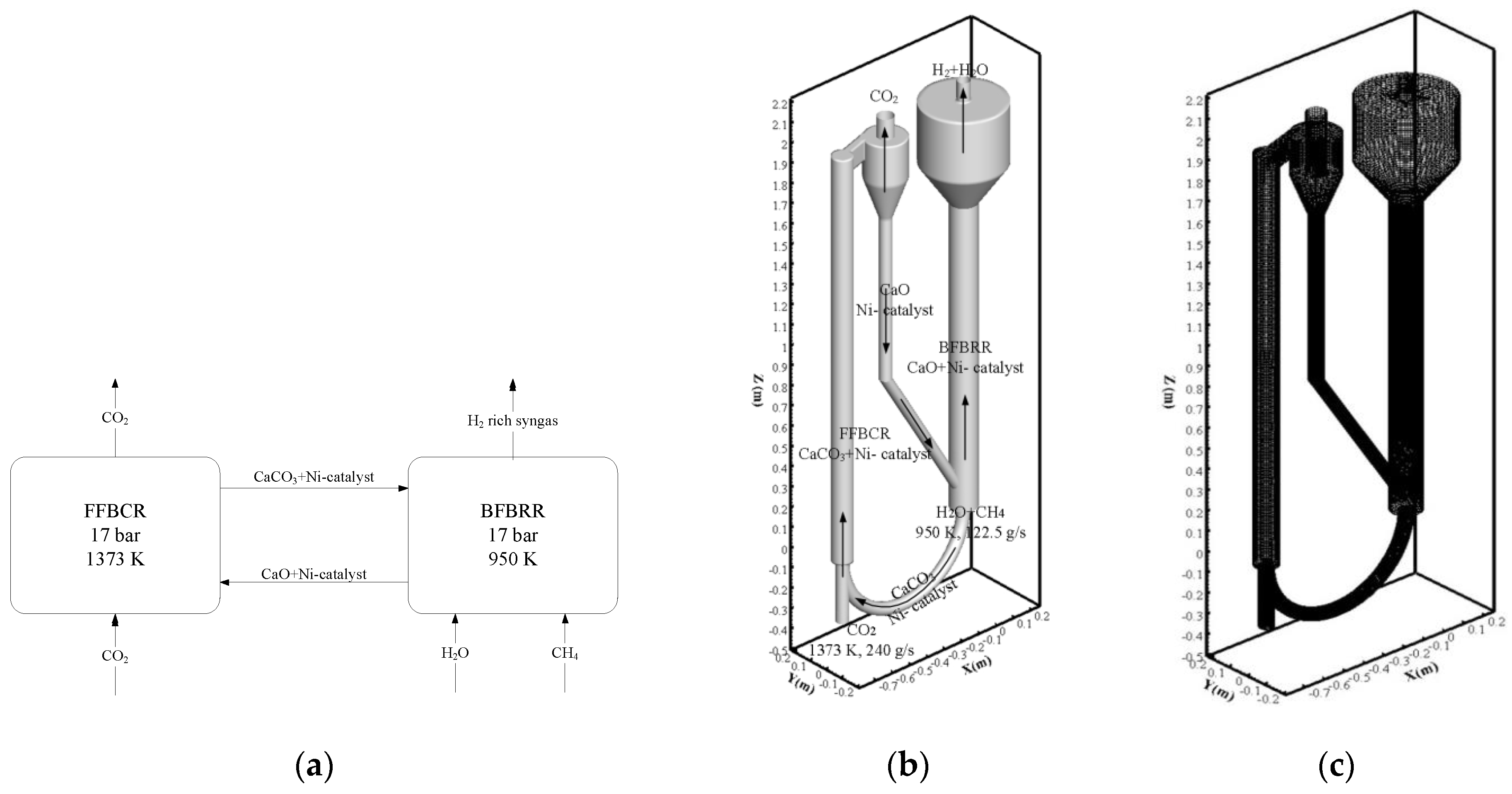
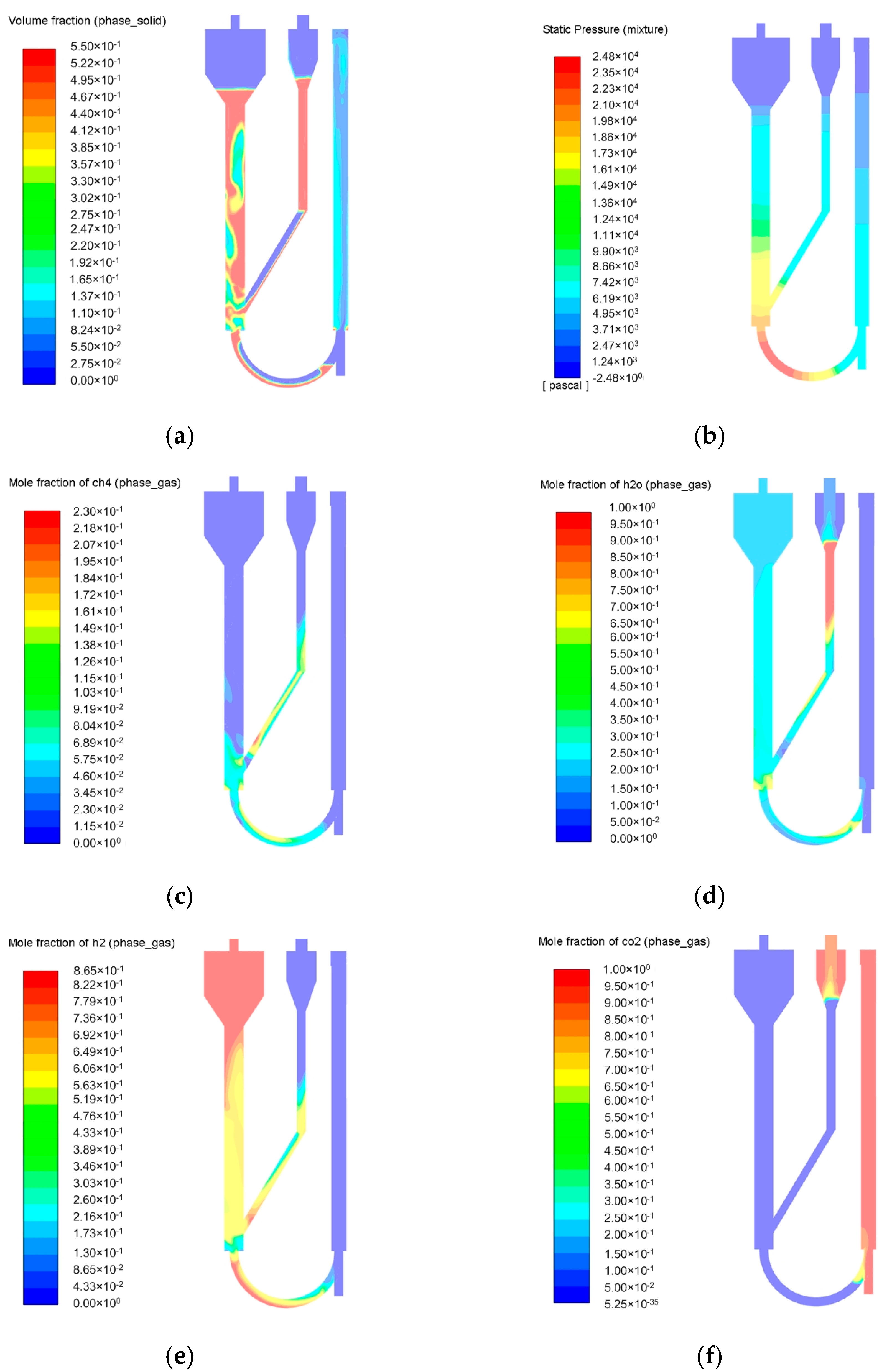
2.2. Simulation of the Pressurized Dual Fluidized Bed Reactor

After the validation, the sorption-enhanced SMR in the pressurized dual fluidized bed reactor was numerically investigated with the model built in this work. The initial temperatures of the BFBRR and the FFBCR were set at 950 K and 1373 K, respectively. The initial static pressure of the dual fluidized bed reactor was 17 bar. The initial total weight of the CaO and the Ni-based catalyst in the reactor was about 44 kg, and the mass fractions of the CaO and the CaCO3 were 0.5 and 0, respectively. The diameter of the bed material was set at 150 μm. The packing limit of the bed material was set at 0.55. To accelerate the transient calculation process, the initial bed-material-volume ratio in the BFBRR was set at 0.545, and that in the FFBCR was set at 0.15. During practical operation, parts of the catalyst and CaO can lose their activity. To solve this issue, a fresh bed material can be added intermittently to the reactor to maintain high activity levels. Otherwise, a bed material with good strength and durability should be used. The inlet temperature and mass-flow rate of the H2O and CH4 mixture were 950 K and 122.5 g/s, respectively. The inlet temperature and mass-flow rate of the CO2 were set at 1373 K and 240 g/s, respectively. The steam-to-carbon molar ratio was set at 4.0. The operating pressure was set at 17 bar to enhance the sorption reaction. The reactor wall was assumed to be adiabatic. This operating condition was given after many trials so that the reactor worked in an efficient and stable state. After 150 s of operation, the operation results were about steady. The key results, including the solid-phase volume-fraction distribution, the pressure field, and the H2 and CO2 mole fractions are shown in Figure 5. It should be noted that although the temperature of the FFBCR should be maintained around 1100 °C, the heat required does not increase obviously with temperature. This is because when the calcination temperature in the FFBCR is high, the outlet CO2 temperature is also high. Therefore, only a small amount of heat is required to heat part of the outlet CO2 to the required temperature before this part of the CO2 is circulated to the FFBCR as a heat carrier. In addition, during the practical operation of the reactor, the waste heat from the reactor can also be recycled and used, so that the whole system’s thermal efficiency can be improved.
In panel (a) in Figure 5, it can be seen that the volume fractions in the bubbling fluidized bed were much higher. This is because the superficial velocity of the BFBRR was about 0.5 m/s, while that of the FFBRC was about 3.0 m/s. It can also be seen that the particles were dense in the leg tube below the cyclone and in the bent tube at the bottom of the reactor. This kind of particle distribution can effectively restrict the mixing of the syngas in the BFBRR and the CO2 in the CFBCR. Moreover, it was found that the particle volume fraction at the cyclone outlet was almost zero, indicating that the separation function of the cyclone is satisfying at this operating condition. In panel (b), it can be seen that the highest pressure was near the bottom of the reactor; this is because the particles were increasingly fluidized. The pressure drop was about 25,000 Pa, which can be a reference value when choosing blowers or gas compressors for dual-bed reactors. In panel (c), it can be seen that CH4 was converted to CO and H2 quickly when contacting the catalytic bed material. This was mainly caused by the action of the catalyst, which greatly accelerated the SMR process. In panel (d), it can be seen that the mole fraction of the H2O sharply decreased near the BFBRR inlet and then maintained a relatively high value along the reactor. This was because the inlet’s steam-to-carbon ratio was high and the H2O was quickly consumed in the BFBRR by the reforming and water–gas-shift reactions. During the presence of the catalyst, the main reactions in the reactor reached an equilibrium state because the reaction rates of both the positive and negative reactions were very fast. It can also be noted that in some other parts of the reactor, H2O was also present. This was because the initial H2O mole fraction in the entire reactor was set to the unit. In panel (e) in Figure 5, it can be seen that the H2 mole fraction in the BFBRR increased with the reactor height, and its wet mole fraction reached 86%. This was mainly due to the methane reforming reaction, the water–gas-shift reaction, and the carbonation reaction. Note that the fraction of H2 cannot be increased by decreasing the steam-to-carbon ratio. This is because lower steam-to-carbon ratios can restrict reforming and water–gas-shift reactions and further restrict H2 production. In panel (f), it can be seen that the CO2 decreased quickly in the BFBRR and was at its highest in the FFBRC. This was mainly due to the carbonation and calcination reactions, which occurred at relatively low and high temperatures, respectively. In panel (g) in Figure 5, it can be seen that the maximum CO mole fraction in the BFBRR was much lower than the maximum mole fraction of other syngas species, and the CO mole-fraction distribution was more homogeneous. This was because CaO can also work as a catalyst in water–gas-shift reactions, and these reaction can reach an equilibrium state quickly. Because the operating thermal condition in the BFBRR was almost homogeneous, the variation in the CO mole fraction was not apparent. In panel (h) in Figure 5, it can be seen that the mole fractions of the CaCO3 increased with the reactor height in the BFBRR, while the mole fraction of the CaCO3 in the FFBCR wa almost zero. This was due to the carbonation reaction in the BFBRR and the calcination reaction in the FFBCR.
In addition, the methane conversion in the dual fluidized bed reactor at the given operating conditions was close to 100%. The H2 mole fraction in the dry syngas was about 98.8%. The CO2-capture ratio was about 96.4%. The cold-gas efficiency of the reactor was 98.5%, which was very promising. It should be noted that when CH4 is completely converted to H2, the cold-gas efficiency can be over 100% because the reaction is endothermic. However, endothermic reactions cannot proceed automatically. Although the sorption-enhanced SMR is exothermic and can theoretically realize autothermal reactions, the regeneration of CaO needs an additional heat supply. When considering the heat supplied to the calcination reaction, the overall cold-gas efficiency becomes 98.5%.

3. Materials and Methods

3.1. Computational Fluid Dynamics Model

The particle-volume fraction in a fluidized bed reactor is high, so the interaction between particles should be carefully considered. For the simulation of a fluidized bed reactor, there are usually various methods, such as the discrete element method, which directly calculates particle interactions and is usually computation-intensive [31], the multiphase particle-in-cell method [32], which calculates particle interactions according to the particles’ volume fraction and has moderate computation intensity, and the Eulerian–Eulerian method, which calculates particle interactions with the granular kinetic theory and is the most efficient method [33]. Because the sorption-enhanced SMR in the dual fluidized bed reactor is very complex, the Eulerian–Eulerian multiphase methodology is used in this work. The gaseous phase is considered the primary phase, while the particulate phase is considered the secondary phase. The momentum exchange, heat exchange, and mass transfer between the two phases are considered by the source terms in the governing equations. The governing equations of the mass conservation, momentum conservation, energy conservation, species conservation, and turbulence for both the gas phase and solid phase are listed in Table 1 [29].
In Table 1, θg and θs denote the gas-phase and solid-phase volume fractions, respectively; ρg and ρs denote the gas density and solid bulk density, respectively; ug and us denote gas-phase and solid-phase velocities; Sgm and Ssm denote interphase mass source; pg and ps denote gas-phase and solid-phase pressures; β denotes the drag coefficient; τg and τs denotes the gas-phase and solid-phase stress tensors; hg and hs denote the gas-phase and solid-phase enthalpies; λg and λs denote the gas and solid thermal conductivities; Tg and Ts denote the gas and solid thermal temperatures; Sgh and Ssh denote the gas and solid thermal temperatures; Yg,i and Ys,i denote the mass fractions of species i in gas and solid phases; D denotes the binary diffusion coefficient; Sg,i and Ss,i denote the mass sources of species i in gas and solid phases; k and ε denote the turbulent kinetic energy and turbulent dissipation rate; Gk is the turbulence-generation source; and Cε1 and Cε2 are the turbulence-calculation constants. The Huilin–Gidaspow model [34] is used to calculate the drag coefficient, β, as shown by Equation (6a–c).
β Ergun = 150 ( 1 θ g ) 2 μ g θ g ( d s ) 2 + 1.75 ( 1 θ g ) u g u s d s
β Wen & Yu = 3 4 C d θ g ( 1 θ g ) ρ g | u g u s | d s θ g 2.65
β = ψ β Ergun + ( 1 ψ ) β Wen & Yu
where βErgun and βWen&Yu denote the drag coefficients obtained by the Ergun model and Wen and Yu’s models. The stitching function, ψ, is in the form of
ψ = 0.5 + arctan [ 262.5 ( θ s 0.2 ) ] π
In addition, the Syamlal–O’Brien model is chosen to calculate the granular viscosity, Lun et al.’s model is chosen to calculate the granular bulk viscosity, the algebraic method is used to calculate the granular temperature, Lun et al.’s method is used to calculate the solids pressure, Lun et al.’s model is used to calculate the particle-phase radial distribution, and the derived method is used to calculate the particle phase elasticity modulus [35].

3.2. The Reaction Kinetics

So far, many reaction kinetic models for methane reforming have been proposed by researchers worldwide. Therefore, choosing the proper kinetic model is essential for the accurate prediction of the numerical simulation model in this work. The kinetic model should be chosen according to the operation condition of the reactions. Because the calcination process is coupled with the reforming process and the reforming is pressurized, the calcination pressure should also be high, so that the particles can circulate between BFBRR and CFBCR. Moreover, to ensure that pure CO2 was generated from the CFBCR to make the carbon capture or utilization feasible, pure CO2 was injected into the CFBCR as fluidization gas. It was then calculated that the calcination temperature should be around 1100 °C to ensure the regeneration of CaO was practically realizable. Therefore, the reforming temperature was kept sufficiently high for the proposed dual fluidized bed reactor to operate stably. However, if the reforming temperature is high, the water–gas-shift reaction can be restricted and the hydrogen fraction in the produced syngas can be lowered. In this case, either the reforming conversion ratio or the carbon capture rate can be adversely affected. In this work, a proper reforming temperature wa chosen: 950 K. In terms of catalysts, Ni-based catalysts offer good performance and are also economical compared with others; they are therefore Ni-based catalyst widely used in methane reforming. Based on the operational conditions of this work, the reaction rate for SMR over nickel-based catalyst can be calculated with a widely used correlation, as shown by Equation (8) [36].
R 1 = k 1 p H 2 2.5 ( p CH 4 p H 2 O p H 2 3 p CO K e q ) / ( 1 + K CO p CO + K H 2 p H 2 + K CH 4 p CH 4 + K H 2 O p H 2 O p H 2 )
where k1 is the reaction constant and can be calculated with the Arrhenius equation; pi is the partial pressure of species i; Keq is the reaction equilibrium constant; and Ki is the adsorption coefficient of species i. The detailed correlations used to obtain these parameters can be found in the literature [37]. The rates of the water–gas-shift reaction and its reverse reaction are calculated by Equations (9) and (10) [38].
k 1 = 2.78 e 3 exp ( 12560 / ( R T g ) )
The reaction rate of calcium carbonation is calculated with Equation (10) [24].
r cab = 5.007 × 10 3 × EXP ( 20300 8.3145 × T ) × ( P CO 2 P CO 2 , eq ) × m CaO
where P CO 2 , eq and P CO 2 denote the equilibrium CO2 pressure and the CO2 partial pressure, respectively, and m CaO is the CaO mass flow rate. The calcination rate (1/s) is calculated according to Equation (11).
r cal = 252015.2 × EXP ( 91700 8.3145 × T ) × ( 1 x cal ) 2 / 3 × ( C CO 2 , eq C CO 2 )
where xcal denotes the conversion of CaCO3, and C CO 2 , eq and C CO 2 denote the CO2 concentrations at the equilibrium state and at any state, respectively.

3.3. Solution Methods

The commercial software, Fluent, was used to solve the governing equations [35]. The computational domain of the dual fluidized bed reactor was discretized with the hybrid hexahedron and tetrahedron cells, as shown in Figure 1b. Grid-independence analysis was conducted by comparing three different meshes with different cell numbers, and, finally, the mesh size of about 34,000 cells is chosen in this work. The second-order implicit scheme was used for the transient term discretization. The divergence terms of the governing equations were spatially discretized with the second-order upwind scheme. The gradient term was addressed with the Green–Gauss cell-based method. The governing equations were solved implicitly with the phase-coupled SIMPLE algorithm, and the transient time step was set as 0.001 s to satisfy both the calculation accuracy and the computation efficiency. The algebraic multigrid scheme was chosen to accelerate the convergence process. The residuals of the energy equations were restricted to below 1 × 10⁻⁶, and those of the other equations were restricted to below 1 × 10⁻³ to ensure iteration accuracy. The reaction kinetic correlations were embedded in the Fluent solver by user-defined functions.

4. Conclusions

To further improve the performance of steam methane reforming (SMR) so that the conversion efficiency can be improved and the carbon emitted can be reduced, a dual fluidized bed reactor was designed for the sorption-enhanced SMR process over a Ni-based catalyst, and a three-dimensional numerical simulation model was built to study the SMR’s properties in the designed reactor. From this research, the following key conclusions can be drawn:
(1)
The numerical simulation model for the sorption-enhanced SRM is solid and can be used to predict similar processes;
(2)
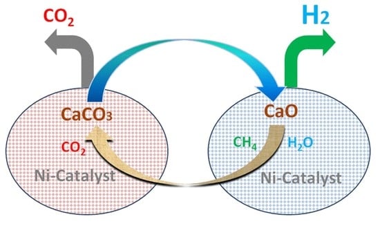
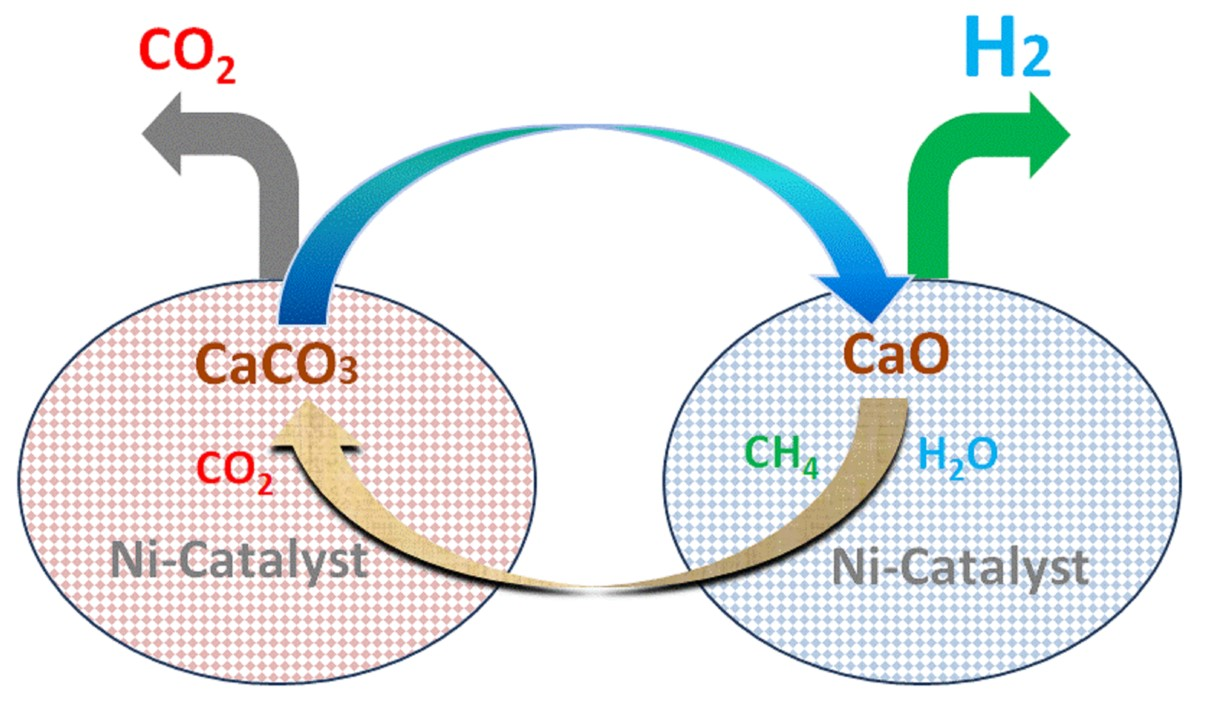
The dual fluidized bed designed for the SMR process operates stably and can be used for H2 production by sorption-enhanced SMR technology;
(3)
The methane conversion in the dual fluidized bed reactor at the given operating condition is close to 100%. The H2 mole fraction in the dry syngas is about 98.8%. The CO2 capture ratio is about 96.4%. The cold-gas efficiency of the reactor is 98.5%.

Author Contributions

Conceptualization, L.Y. and K.L.; methodology, L.Y. and K.L.; software, L.Y. and K.L.; validation, L.Y. and K.L.; formal analysis, L.Y., K.L. and H.S.; investigation, K.L. and H.S.; resources, L.Y.; data curation, L.Y., K.L. and H.S.; writing—original draft preparation, L.Y., K.L., H.S., C.G., B.H. and B.F.; writing—review and editing, L.Y. and B.F.; visualization, L.Y. and B.F.; supervision, L.Y.; project administration, L.Y.; funding acquisition, L.Y. All authors have read and agreed to the published version of the manuscript.

Funding

This research was funded by the National Natural Science Foundation of China (51706012), and the APC was waived by the editorial office.

Data Availability Statement

The data presented in this study are available on request from the corresponding author.

Acknowledgments

The authors gratefully acknowledge the financial support from the National Natural Science Foundation of China (NSFC, 51706012) for this work.

Conflicts of Interest

The authors declare no conflict of interest.

References

  1. Kamshybayeva, G.K.; Kossalbayev, B.D.; Sadvakasova, A.K.; Kakimova, A.B.; Bauenova, M.O.; Zayadan, B.K.; Lan, C.-W.; Alwasel, S.; Tomo, T.; Chang, J.-S.; et al. Genetic engineering contribution to developing cyanobacteria-based hydrogen energy to reduce carbon emissions and establish a hydrogen economy. Int. J. Hydrogen Energy 2023. [Google Scholar] [CrossRef]
  2. Kalamaras, C.M.; Efstathiou, A.M. Hydrogen production technologies: Current state and future developments. Conf. Pap. Energy 2013, 2013, 1–9. [Google Scholar] [CrossRef] [Green Version]
  3. Ogden, J.M.; Steinbugler, M.M.; Kreutz, T.G. Cmparison of hydrogen, methanol and gasoline as fuels for fuel cell vehicles: Implications for vehicle design and infrastructure development. J. Power Sources 1999, 79, 143–168. [Google Scholar] [CrossRef]
  4. Hohn, K.L.; Schmidt, L.D. Partial oxidation of methane to syngas at high space velocities over Rh-coated spheres. Appl. Catal. A 2001, 211, 53–68. [Google Scholar] [CrossRef]
  5. Joensen, F.; Rostrup-Nielsen, J.R. Conversion of hydrocarbons and alcohols for fuel cells. J. Power Sources 2002, 105, 195–201. [Google Scholar] [CrossRef]
  6. Bromberg, L.; Cohn, D.R.; Rabinovich, A. Plasma reformer-fuel cell system for decentralized power applications. Int. J. Hydrogen Energy 1997, 22, 83–94. [Google Scholar] [CrossRef] [Green Version]
  7. Demirbas, M.F. Hydrogen from various biomass species via pyrolysis and steam gasification processes. Energy Sources 2006, 28, 245–252. [Google Scholar] [CrossRef]
  8. Demirbaş, A. Recovery of chemicals and gasoline-range fuels from plastic wastes via pyrolysis. Energy Sources 2005, 27, 1313–1319. [Google Scholar] [CrossRef]
  9. Davda, R.R.; Shabaker, J.W.; Huber, G.W.; Cortright, R.D.; Dumesic, J.A. Aqueous-phase reforming of ethylene glycol on silica-supported metal catalysts. Appl. Catal. B 2003, 43, 13–26. [Google Scholar] [CrossRef]
  10. Turner, J.; Sverdrup, G.; Mann, M.K.; Maness, P.C.; Kroposki, B.; Ghirardi, M.; Evans, R.J.; Blake, D. Renewable hydrogen production. Int. J. Energy Res. 2008, 32, 379–407. [Google Scholar] [CrossRef] [Green Version]
  11. Hamelinck, C.N.; Faaij, A.P.C. Future prospects for production of methanol and hydrogen from biomass. J. Power Sources 2002, 111, 1–22. [Google Scholar] [CrossRef]
  12. Steinfeld, A. Solar thermochemical production of hydrogen—A review. Sol. Energy 2005, 78, 603–615. [Google Scholar] [CrossRef]
  13. Oh, K.; Kim, D.; Lim, K.; Ju, H. Multidimensional modeling of steam methane reforming based fuel processor for hydrogen production. Fusion Sci. Technol. 2020, 76, 415–423. [Google Scholar] [CrossRef]
  14. Cherif, A.; Nebbali, R.; Sen, F.; Sheffeld, J.W.; Doner, N.; Nasser, L. Modeling and simulation of steam methane reforming and methane combustion over continuous and segmented catalyst beds in autothermal reactor. Int. J. Hydrogen Energy 2022, 47, 9127–9138. [Google Scholar] [CrossRef]
  15. Sadeghi, M.T.; Molaei, M. CFD simulation of a methane steam reforming reactor. Int. J. Chem. React. Eng. 2008, 6, 1–12. [Google Scholar] [CrossRef]
  16. Wang, H.; Yang, G.G.; Li, S.; Shen, Q.W.; Li, Z.; Chen, B.J. Numerical study on the effect of discrete catalytic layer arrangement on methane steam reforming performance. RSC Adv. 2021, 11, 2958–2967. [Google Scholar] [CrossRef]
  17. Chen, K.; Zhao, Y.; Zhang, W.; Feng, D.; Sun, S. The intrinsic kinetics of methane steam reforming over a nickel-based catalyst in a micro fluidized bed reaction system. Int. J. Hydrogen Energy 2019, 43, 1615–1628. [Google Scholar] [CrossRef]
  18. Cownden, R.; Mullen, D.; Lucquiaud, M. Towards net-zero compatible hydrogen from steam reformation—Techno-economic analysis of process design options. Int. J. Hydrogen Energy 2023. [Google Scholar] [CrossRef]
  19. Wu, W.; Tungpanututh, C. Optimization of a methane autothermal reforming-based hydrogen production system with low CO2 emissions. IFAC Proc. Vol. 2012, 15, 661–666. [Google Scholar] [CrossRef] [Green Version]
  20. Vanga, G.; Gattia, D.M.; Stendardo, S.; Scaccia, S. Novel synthesis of combined CaO-Ca12Al14O33-Ni sorbent-catalyst material for sorption enhanced steam reforming processes. Ceram. Int. 2019, 45, 7594–7605. [Google Scholar] [CrossRef]
  21. Menikpura, S.N.M.; Basnayake, B.F.A. New applications of ‘Hess Law’ and comparisons with models for determining calorific values of municipal solid wastes in the Sri Lankan context. Renew. Energy 2009, 6, 1587–1594. [Google Scholar] [CrossRef]
  22. George, W.R. Chemical Reactions and Chemical Reactors; John Wiley and Sons, Inc.: Hoboken, NJ, USA, 2009. [Google Scholar]
  23. Powell, J.; Wongsakulphasatch, S.; Kokoo, R.; Noppakun, N.; Prapainainar, C.; Aziz, M.A.A.; Assabumrungrat, S. Optimisation of a sorption-enhanced chemical looping steam methane reforming process. Chem. Eng. Res. Des. 2021, 173, 183–192. [Google Scholar] [CrossRef]
  24. Carlo, A.D.; Bocci, E.; Zuccari, F.; Dell’Era, A. Numerical investigation of sorption enhanced steam methane reforming process using computational fluid dynamics Eulerian-Eulerian Code. Ind. Eng. Chem. Res. 2010, 49, 1561–1576. [Google Scholar] [CrossRef]
  25. Fernandez, J.R.; Abanades, J.C.; Grasa, G. Modeling of sorption enhanced steam methane reforming-Part II: Simulation within a novel Ca/Cu chemical loop process for hydrogen production. Chem. Eng. Sci. 2012, 84, 12–20. [Google Scholar] [CrossRef] [Green Version]
  26. Giuliano, A.D.; Gin, J.; Massacesi, R.; Gallucci, K.; Courson, C. Sorption enhanced steam methane reforming by Ni-CaO materials supported on mayenite. Int. J. Hydrogen Energy 2017, 19, 13661–13680. [Google Scholar] [CrossRef]
  27. Nardo, A.D.; Calchetti, G.; Carlo, A.; Stendardo, S. Sorption enhanced steam methane reforming in a bubbling fluidized bed reactor: Simulation and analysis by the CPFD method. Comput. Chem. Eng. 2023, 169, 108080. [Google Scholar] [CrossRef]
  28. Solsvik, J.; Chao, Z.; Sánchez, R.A.; Jakobsen, H.A. Numerical investigation of steam methane reforming with CO2-capture in bubbling fluidized bed reactors. Fuel Process. Technol. 2014, 125, 290–300. [Google Scholar] [CrossRef]
  29. Yan, L.; Cao, Y.; Zhou, H.; He, B. Investigation on biomass steam gasification in a dual fluidized bed reactor with the granular kinetic theory. Bioresour. Technol. 2018, 269, 384–392. [Google Scholar] [CrossRef]
  30. Bokkers, G.A.; Annaland, M.S.; Kuipers, J.A.M. Mixing and segregation in a bi-disperse gas-solid fluidised bed: A numerical and experimental study. Powder Technol. 2004, 140, 176–186. [Google Scholar] [CrossRef]
  31. Gerber, S.; Oevermann, M. A two dimensional Euler–Lagrangian model of wood gasification in a charcoal bed—Part I: Model description and base scenario. Fuel 2014, 115, 385–400. [Google Scholar] [CrossRef]
  32. Yan, L.; Lim, C.J.; Yue, G.; He, B.; Grace, J.R. Simulation of biomass-steam gasification in fluidized bed reactors: Model setup, comparisons and preliminary predictions. Bioresour. Technol. 2016, 221, 625–635. [Google Scholar] [CrossRef]
  33. Li, T.; Mahecha-Botero, A.; Grace, J.R. Computational Fluid Dynamic Investigation of Change of Volumetric Flow in Fluidized-Bed Reactors. Ind. Eng. Chem. Res. 2010, 45, 6780–6789. [Google Scholar] [CrossRef]
  34. Lu, H.L.; Gidaspow, D. Hydrodynamics of binary fluidization in a riser: CFD simulation using two granular temperatures. Chem. Eng. Sci. 2003, 58, 3777–3792. [Google Scholar]
  35. ANSYS FLUENT User’s Guide; Version 19.0; ANSYS Inc.: Canonsburg, PA, USA, 2018.
  36. Xu, J.; Froment, G.F. Methane Steam Reforming, Methanation and Water-Gas Shift: 1. Intrinsic Kinetics. AIChE J. 1989, 35, 88–96. [Google Scholar] [CrossRef]
  37. Morf, P.; Hasler, P.; Nussbaumer, T. Mechanisms and kinetics of homogeneous secondary reactions of tar from continuous pyrolysis of wood chips. Fuel 2002, 81, 843–853. [Google Scholar] [CrossRef]
  38. Yan, L.; Cao, Y.; Li, X.; He, B. On a carbon-negative energy production scheme via a quadruple fluidized bed gasifier. Energy Convers. Manag. 2018, 171, 326–338. [Google Scholar] [CrossRef]
Figure 1. The dual fluidized bed reactor’s configuration. (a) Technical flow sheet of the dual fluidized bed reactor. (b) Structure of the dual fluidized bed reactor. (c) Mesh of the computational zone.
Inorganics 11 00107 g001
Figure 2. Experimental (left) and predicted (right) particle distribution at 150 mm.
Inorganics 11 00107 g002
Figure 3. Experimental fluidized bed configuration.
Inorganics 11 00107 g003
Figure 4. Comparison between the experiment and simulation.
Inorganics 11 00107 g004
Figure 5. (a) Solid-phase volume fraction. (b) Static pressure distribution. (c) CH4 mole-fraction distribution. (d) H2O mole-fraction distribution. (e) H2 mole-fraction distribution. (f) CO2 mole-fraction distribution. (g) CO mole-fraction distribution (h) CaCO3 mole-fraction distribution.
Inorganics 11 00107 g005aInorganics 11 00107 g005b
Table 1. Governing equations of the Eulerian–Eulerian model.
The mass-conservation equations
( θ g ρ g ) t + ( θ g ρ g u g ) = S g m (1a)
( θ s ρ s ) t + ( θ s ρ s u s ) = S s m (1b)
The momentum-conservation equations
( θ g ρ g u g ) t + ( θ g ρ g u g u g ) = θ g p g + β ( u g u s ) + θ g ρ g g + ( θ g τ g ) (2a)
( θ s ρ s u s ) t + ( θ s ρ s u s u s ) = θ s p s β ( u g u s ) + θ s ρ s g + ( θ s τ s ) (2b)
The energy-conservation equations
( θ g ρ g h g ) t + ( θ g ρ g u g h g ) = ( λ g T g ) + h g s ( T s T g ) + S g (3a)
( θ s ρ s h s ) t + ( θ s ρ s u s h s ) = ( λ s T s ) + h g s ( T g T s ) + S s (3b)
The species-transportation equation
( θ g ρ g Y g , i ) t + ( θ g ρ g u g Y g , i ) = ( ρ g D θ g Y g , i ) + S g , i (4a)
( θ s ρ s Y s , i ) t + ( θ s ρ s u s Y s , i ) = S s , i (4b)
The turbulence equations
( θ g ρ g k ) t + ( θ g ρ g u g k ) = ( θ g μ t σ k k ) + θ g G k θ g ρ g ε (5a)
( θ g ρ g ε ) t + ( θ g ρ g u g ε ) = ( θ g μ t σ k ε ) + θ g C ε 1 G k θ g C ε 2 ρ g ε (5b)
Disclaimer/Publisher’s Note: The statements, opinions and data contained in all publications are solely those of the individual author(s) and contributor(s) and not of MDPI and/or the editor(s). MDPI and/or the editor(s) disclaim responsibility for any injury to people or property resulting from any ideas, methods, instructions or products referred to in the content.

