1. Introduction
Reducing the levelized cost of energy (LCOE) is a value used to compare the cost of producing energy from various sources over the lifespan of a power station. In recent years, renewable energy sources such as wind, solar, hydro, and geothermal have grown more competitive owing to technological advancements and economies of scale. The LCOE of renewable energy varies based on location, resource availability, financing costs, and used technology, among other different factors. In general, however, the LCOE of renewable energy has been decreasing, making it more cost-competitive with power derived from fossil fuels. LCOE of crystalline silicon (c-Si) solar cells is essential in order to replace existing energy technologies such as nuclear and coal power plants [
1]. Several types of c-Si solar cells have been or are being developed to decrease the LCOE by decreasing the manufacturing cost and increasing light conversion efficiency [
2]. These include passivated emitter solar cells (PESCs) [
3], passivated emitter and rear cells (PERCs) [
4], interdigitated back-contact (IBC) solar cells [
5], passivated emitter rear-locally diffused cells (PERLs) [
6,
7], and heterojunction c-Si (SHJ) solar cells [
3]. Among them, SHJ solar cells have demonstrated efficiencies of up to 26.7% [
4], making them strong candidates for reducing LCOE. Even though the SHJ solar cell shows high efficiency, the technologies to increase its efficiency should be studied to decrease LCOE.
In order to increase the efficiency of SHJ solar cells, many technologies to improve solar cell parameters, such as short circuit current density (J
SC), open circuit voltage (V
OC), and fill factor (FF) have been proposed. Surface passivation of SHJ solar cells is crucial to reduce carrier recombination and improve their V
OC. Amorphous Si is used as a passivation layer in SHJ solar cells to improve them. It is also used as a carrier-selective layer, which helps to separate the electrons and holes in the SHJ solar cell efficiency [
8]. In order to get a high V
OC in SHJ solar cells, optimizing amorphous Si is essential. J. Sritharathikhun et al. investigated the use of intrinsic hydrogenated amorphous Si oxide as a buffer layer in the interplay with doped microcrystalline Si oxide layers to improve the efficiency of SHJ solar cells [
9]. Post-deposition argon plasma treatment was also demonstrated to improve the amorphous Si passivation layer for SHJ solar cells [
8]. Meanwhile, in order to increase FF, researchers are investigating ways to decrease series resistance in SHJ solar cells. One study used several approaches to obtain a low series resistance for a state-of-the-art 2 cm × 2 cm screen-printed solar cell reaching 82.5% FF. [
10]. Research related to copper plating is also conducted in the metallization of SHJ solar cells because the performance of the copper-plated solar cell showed enhanced characteristics as compared to that of a reference solar cell built by silver screen printing. Especially, because copper plating has enormous advantages such as low cost, improving J
SC by fine line plating, and a low temperature process, copper-plating on SHJ solar cells has attracted the attention of many researchers. A new plated metallization process for SHJ solar cells involves selective plating of copper onto a positively masking seed [
11]. Researchers have developed a laser-based method for the metallization of SHJ solar cells by copper-plating [
12]. Selective copper electroplating without any resist-mask is also being developed for SHJ solar cells [
13]. In addition, studies related to the seed layer were also investigated and reported decreased series resistance [
14]. In terms of studies related to J
SC, one of the most promising research trends in improving J
SC for SHJ solar cells is anti-reflection coating (ARC) by using the development of new materials and structures that can enhance light trapping and absorption in SHJ solar cells [
15,
16,
17]. For instance, researchers have investigated the use of nanoparticle coatings, plasmonic structures, and microtextured surfaces to improve the light absorption of SHJ solar cells. In laboratory tests, these methods have demonstrated promise, but additional study is required to optimize their efficacy and scale up their production. Integration of many layers of coatings to improve light absorption and minimize reflection is another significant development in SHJ solar cell research. Researchers have created multilayer antireflective coatings (DLARCs) that use a combination of dielectric and metallic layers to reduce reflection over a broad spectrum of wavelengths [
18,
19]. These multilayer coatings can increase the efficiency of SHJ solar cells by up to 20%, making them extremely promising for commercial use [
20]. In addition to the optimization of materials and structures, there has been extensive research into the creation of cost-effective and scalable production procedures for ARCs. For instance, researchers have investigated the use of sol-gel processes, electrochemical deposition, and printing methods to create extremely efficient and inexpensive ARCs [
21,
22]. These strategies could drastically cut the cost of solar cell production and increase solar energy’s accessibility to a wider spectrum of consumers. Among various technologies, ARC on indium tin oxide (ITO) have attracted attention due to its possibility to increase J
SC and reliability of the solar cell. Improved J
SC was demonstrated by employing indium zinc oxide (IZO)/ITO stacked structure [
23]. A HfO
2-deposited SHJ solar cell also exhibited high current density [
24]. Yamamoto et al. reported that the J
SC and reliability of a SHJ solar cell was increased via deposition of a silicon dioxide (SiO
2) layer [
25]. Although the possibility of SiO
2 ARC on SHJ solar cell has been demonstrated by several institutes, it requires relative thickness of 84 nm [
24], which could lead to the degradation of passivation quality and efficiency during the deposition. Therefore, ARC studies, which feature a thin insulator, should be conducted.
Aluminum oxide (Al
2O
3), which is widely used in the c-Si solar cell industry, can be one of the candidates for ARC [
26,
27,
28]. In the reported literature, the possibility of Al
2O
3 ARC to increase J
SC has been shown with thinner thickness of 35 nm [
24], while it was not demonstrated yet. Therefore, in the present study, we investigate the influence of Al
2O
3 ARC on SHJ solar cell.
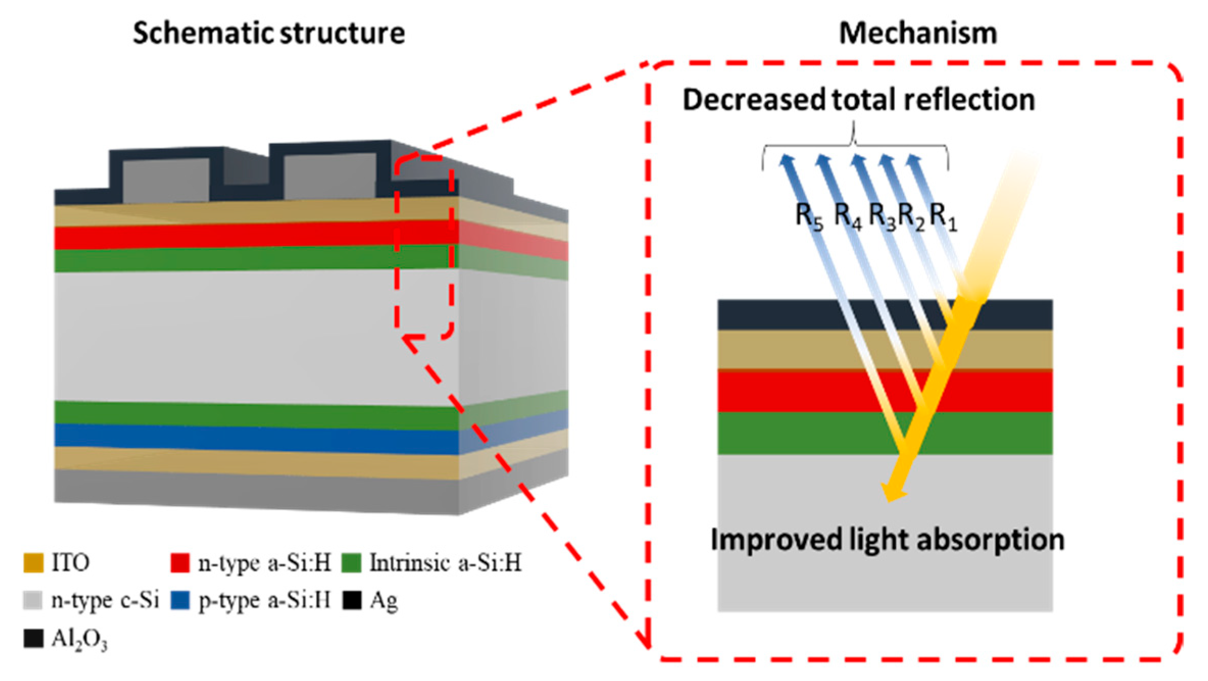
Figure 1 shows schematic structure of the SHJ solar cell with Al
2O
3 and brief mechanism of it, indicating that the interference of the reflected lights can decrease the total reflectance, resulting in the increase of J
SC. In order to evaluate its feasibility, ARC characteristics of Al
2O
3 were analyzed where the configuration of the Al
2O
3 and ITO layer thickness and the ITO dopant concentration that afforded the highest J
SC was identified. Based on the results of the simulations, we experimentally demonstrated SHJ solar cells with an Al
2O
3 layer of various thicknesses in SHJ solar cells and analyzed the properties of the cells.
2. Materials and Methods
In order to analyze the effects of Al
2O
3, OPAL 2 program is employed because it is a simulation program designed for the study of ARC [
29]. The program employs a complex algorithm to evaluate the dependence of refractive index on wavelength [
30]. The light-trapping model is expressed by Z = 4 + {ln[n
2 + (1 − n
2) × exp
−4αW]}/αW where Z is the optical pathlength, n is the refractive index of the ARC, α is the polarization angle, and W is the thickness of the substrate.
The air/Al2O3/ITO/Si substrate structure is used in our OPAL 2 simulations. A 180-µm thick c-Si substrate was selected, and random upright pyramids with a characteristic angle of 54.74° were applied as texture structures. The dopant concentration in the ITO layer on the c-Si substrate was set to 2.0 × 10²⁰, 4.9 × 10²⁰, and 6.0 × 10²⁰/cm3. The ‘Al2O3 on glass (Kum09)’ option was selected for the Al2O3 layer. AM 1.5 G was selected for incident illumination at a 0° zenith angle to the normal of the plane of the cell. The total current density from the light source was fixed at 44 mA/cm2. The reflected current density (JR), the absorbed current density in the Al2O3 and ITO layers (JA), and the absorbed current density in the c-Si (generation current density, JG) were analyzed. The dependence of current density on the Al2O3 and ITO layer thickness and the ITO dopant concentration was evaluated, and the relationship between reflectance and wavelength was determined.
Amorphous i/n-type and i/p-type Si layers were applied to the substrates via plasma-enhanced chemical vapor deposition (PECVD, PlasmaPro System100, Oxford Instruments, Abingdon, UK). ITO layers 80 nm thick were deposited by using sputter (KVS-2000L, Korea Vacuum Tech, Gimpo-si, Republic of Korea) on the n-and p-type layers. Ag evaporation via e-beam evaporator with deposition rate of 0.5 Å/s was performed following a photolithography process. Al
2O
3 was deposited by atomic layer deposition (ALD, THECO 200M, WONIK IPS, Pyongtaek, Republic of Korea) using trimethylaluminium (TMA) and O
2 plasma as precursor and oxidant, respectively. The ALD was heated up to 250 °C, and the thickness of Al
2O
3 was controlled by the number of deposition cycles. In order to investigate the possibility to improve J
SC, the reflectance of the SHJ solar cell with Al
2O
3 layer was measured by UV-visible spectroscopy (Cary-5000, Agilent Technologies, Santa Clara, CA, USA) and weighted reflectance was calculated from the measured reflectance data by the equation as follows. Solar–weighted R = (∫(S(λ) × R(λ) × Δλ))/(∫(S(λ) × Δλ)), where R(λ) is the measured reflectance, and S
λ is the solar irradiance (AM 1.5 G) [
31]. In order to investigate the effect of Al
2O
3 ARC directly on SHJ solar cell, the solar cell parameters were measured before and after Al
2O
3 deposition under illumination with a solar simulator (K201-LAB 50, McScience, Suwon, Republic of Korea). In addition, the external quantum efficiency (EQE) of each cell before and after Al
2O
3 deposition was measured to compare ARC performance.
3. Results
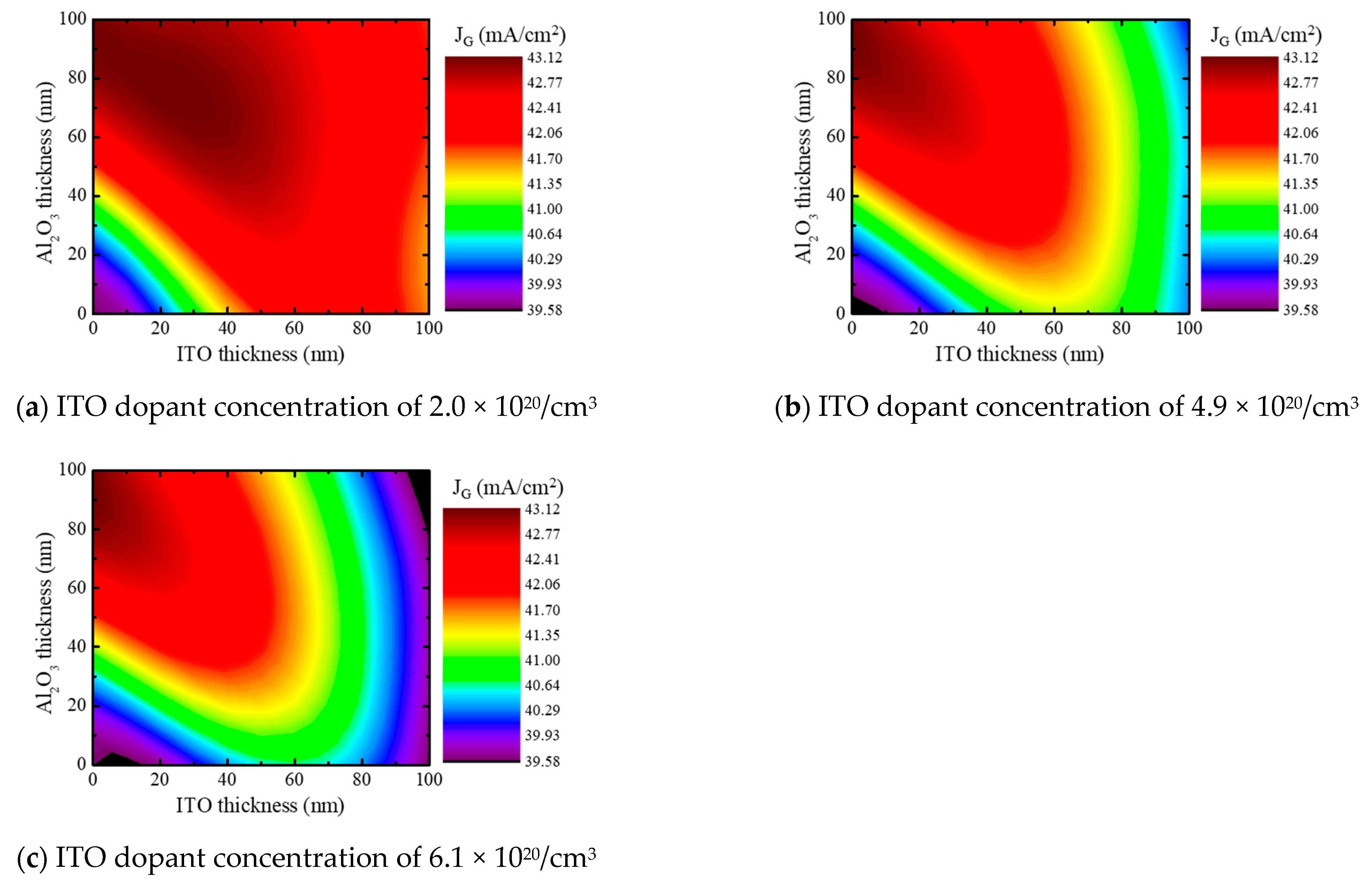
In order to investigate the influence of Al
2O
3 on SHJ solar cell, the dependence of J
G the Al
2O
3 and ITO layer thickness and the ITO dopant concentration is investigated, as shown in
Figure 2. Trend of J
G was generally increased when the Al
2O
3 and ITO layer was thick and thin, and the maximum J
G was 43.12 mA/cm
2 for all dopant concentration. In the case of ITO dopant concentration of 2.1 × 10
20/cm
3, the maximum J
G was observed as the thickness of Al
2O
3 and ITO was 70 and 30 nm. In the case of ITO dopant concentration of 4.9 × 10
20 and 6.1 × 10
20/cm
3, the maximum J
G was observed with the structure without ITO. In order to obtain the proper electric conductivity for the SHJ solar cells, the thickness of the ITO layer have to resemble that of an actual solar cell. The ITO layer in an actual SHJ cell is typically 50–100 nm thick [
25]. So as to analyze the influence of Al
2O
3 to the practical SHJ solar cell, the optimized ITO thickness was obtained via the Air/ITO/c-Si structure without Al
2O
3. The optimized ITO thickness without Al
2O
3 to maximize J
G was 68, 63, and 59 nm for the ITO dopant concentration of 2.1 × 10
20, 4.9 × 10
20, and 6.1 × 10
20/cm
3. Based on the optimized ITO, the influence of Al
2O
3 thickness was then analyzed.
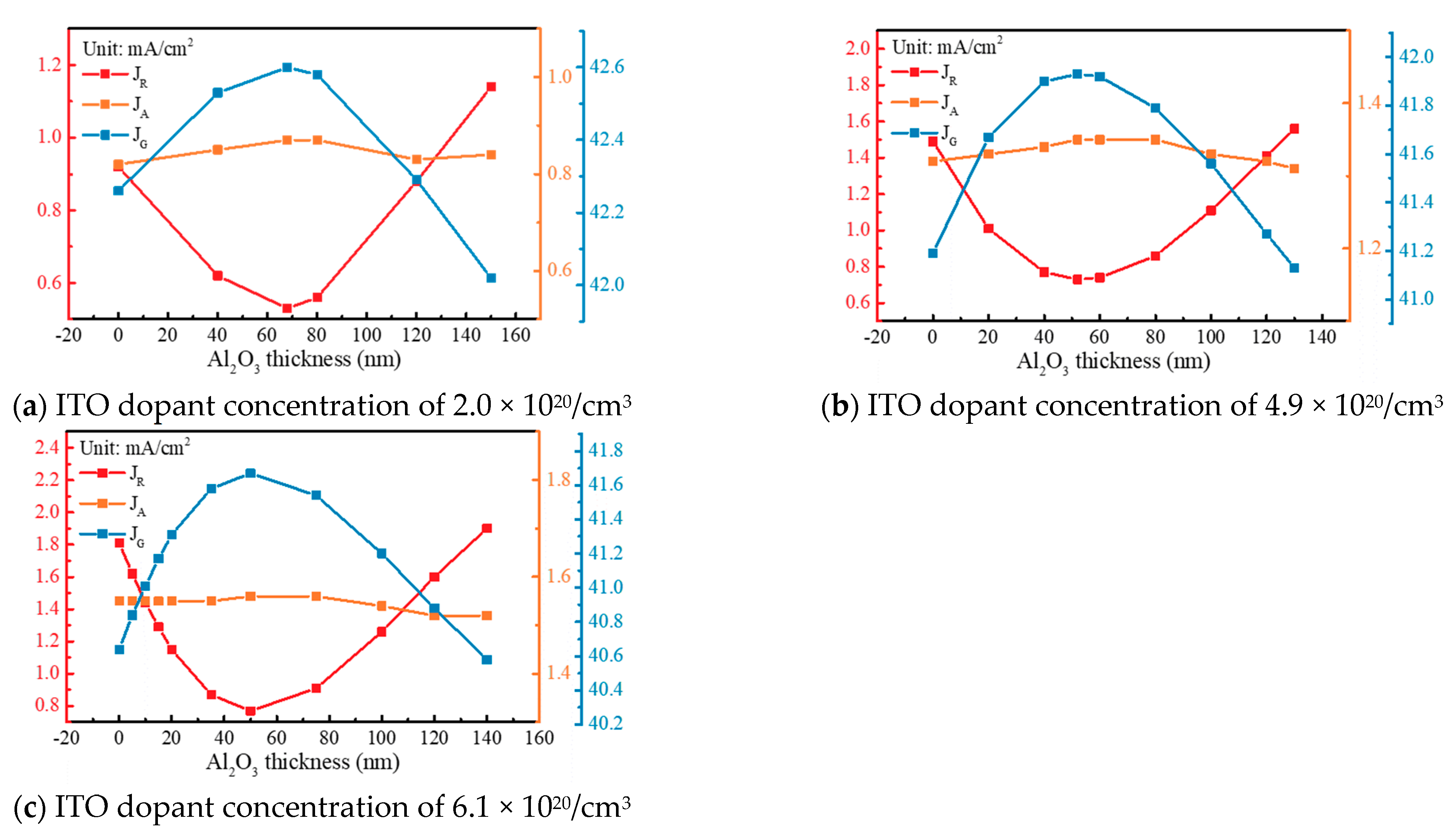
Figure 3 shows the J
G, J
R, and J
A depending on the thickness of Al
2O
3 and doping concentrations of ITO. At an ITO dopant concentration of 2.0 × 10
20/cm
3, J
G increased from 42.26 to 42.60 mA/cm
2 when a 68 nm-thick Al
2O
3 layer was deposited on the optimized ITO. At an ITO dopant concentration of 4.9 and 6.1 × 10
20/cm
3, the deposition of 52 and 50 nm-thick Al
2O
3 layer for each concentration yielded an increased J
G from 41.19 and 40.64 to 41.93 and 41.67 mA/cm
2. The J
G, however, was decreased as the thickness of Al
2O
3 was continuously increased. In addition, all simulation results indicated that the J
A manifested minor changes with respect to the thickness of Al
2O
3, whereas J
G was dominantly affected by J
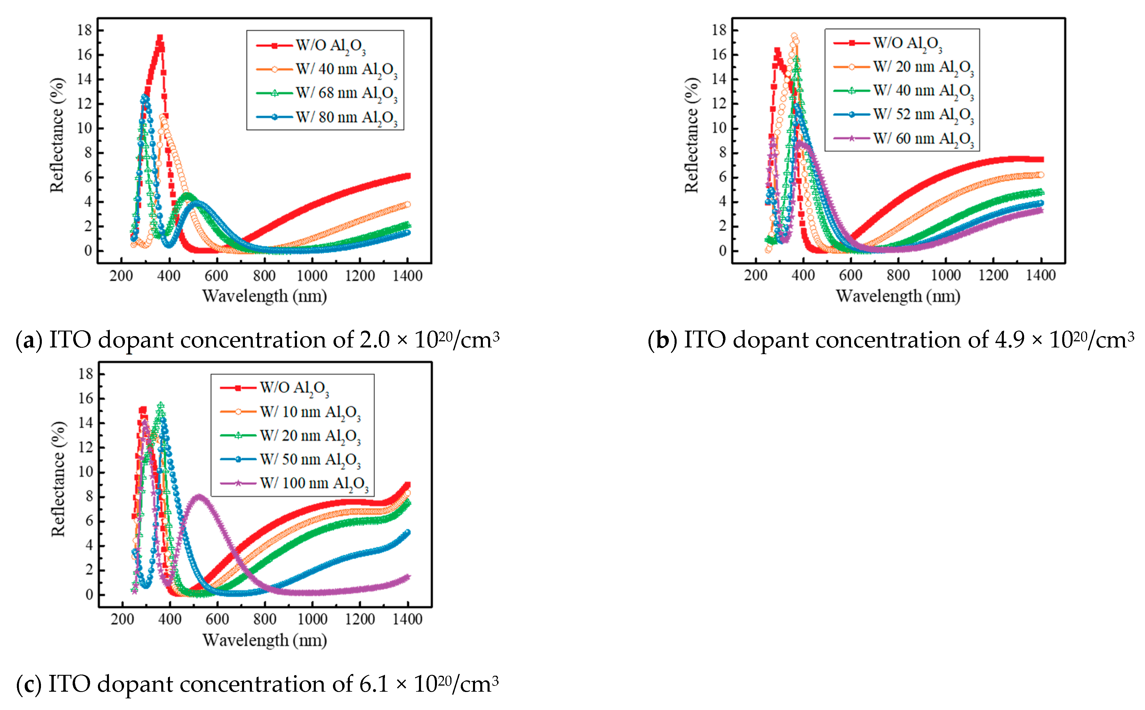
R. In order to investigate the change in the reflectance in detail, we investigated the reflectance according to wavelength, as shown in
Figure 4. At an ITO dopant concentration of 2.0 × 10
20/cm
3, reflectance of light at wavelengths from 400 to 700 nm was increased by Al
2O
3 deposition, whereas the reflectance of wavelengths in other range was reduced, as shown in
Figure 4a. At ITO dopant concentrations of 4.9 × 10
20 and 6.1 × 10
20/cm
3, the trends of increased and decreased reflectance at each wavelength range were similar to that observed with 2.0 × 10
20/cm
3 ITO dopant, as shown in
Figure 4b,c. It is because the construction and destruction interference at wavelengths was shifted after deposition of Al
2O
3, which corresponded to the literatures [
23,
24]. In detail, it was due to the effects of ARCs. ARCs are thin films put on a material’s surface to reduce the amount of light reflected at the interface of materials and a substrate. These coatings are intended to match the refractive index of the material with that of a substrate, hence decreasing surface reflection. The antireflection coating’s thickness is crucial to its efficiency, and it must be properly regulated to obtain the necessary amount of reflection reduction. Single layer antireflection coatings, which is commonly used, consist of a single thin film deposited on a Si wafer. The thickness of the film is chosen to minimize the reflection at a specific wavelength, which is usually the wavelength of the light source being used for SHJ solar cells. The refractive index of the film is also carefully selected to match the refractive index of a Si wafer. For SHJ solar cells, the thicknesses of the ITO and amorphous i/n-type Si layers are optimized to minimize reflections in the visible light region from the front. In general, researchers want to get the lowest reflectance in the visible range because that is where the intensity of light is the strongest, resulting in enabling to maximize the efficiency of the solar cell. A shown in
Figure 4, the lowest reflectance was thus observed in the wavelength range between 400 and 600 nm when only the ITO was deposited. However, as the industry demands higher efficiency from solar cells, DLARCs technology is being used to further minimize the reflections. In a DLARC, two thin films of materials with different refractive indices are typically placed on a substrate. Thickness of each layer is carefully selected so that the two layers interact in a manner that cancels out the reflections that would be generated by each layer independently. As a result of the interaction, the result is an exceptionally low degree of reflection across a broad spectrum of wavelengths. The main concept underlying DLACs is construction and destruction interference of light. Light interacts with the atoms and molecules that make up a substance as it passes through it. Consequently, the velocity of the light changes, causing it to bend or refract. The degree of bending depends on the refractive index of the materials. The refractive indices of the two layers of material in a double-layer antireflection coating are different. When light passes from one material to another, light interacts with both layers, resulting in the reflectance change with respect to the wavelength. In
Figure 4b, we observed the change in reflectance for each wavelength after the deposition of Al
2O
3 as above. This was due to the interaction between the light reflected from the Al
2O
3 and the light reflected from the ITO as the Al
2O
3 was deposited, as mentioned above. The trend of reflectance was also changed as the thickness of the Al
2O
3 increased, indicating that to maximize the efficiency of the solar cell, the thickness of each layer must be adjusted so that the light reflected by one layer adequately interferes with the light reflected by the other layer. Accordingly, the simulation results demonstrated that Al
2O
3 layer of a certain thickness can improve the J
G, and the ITO dopant concentration had an effect on the J
G as well.
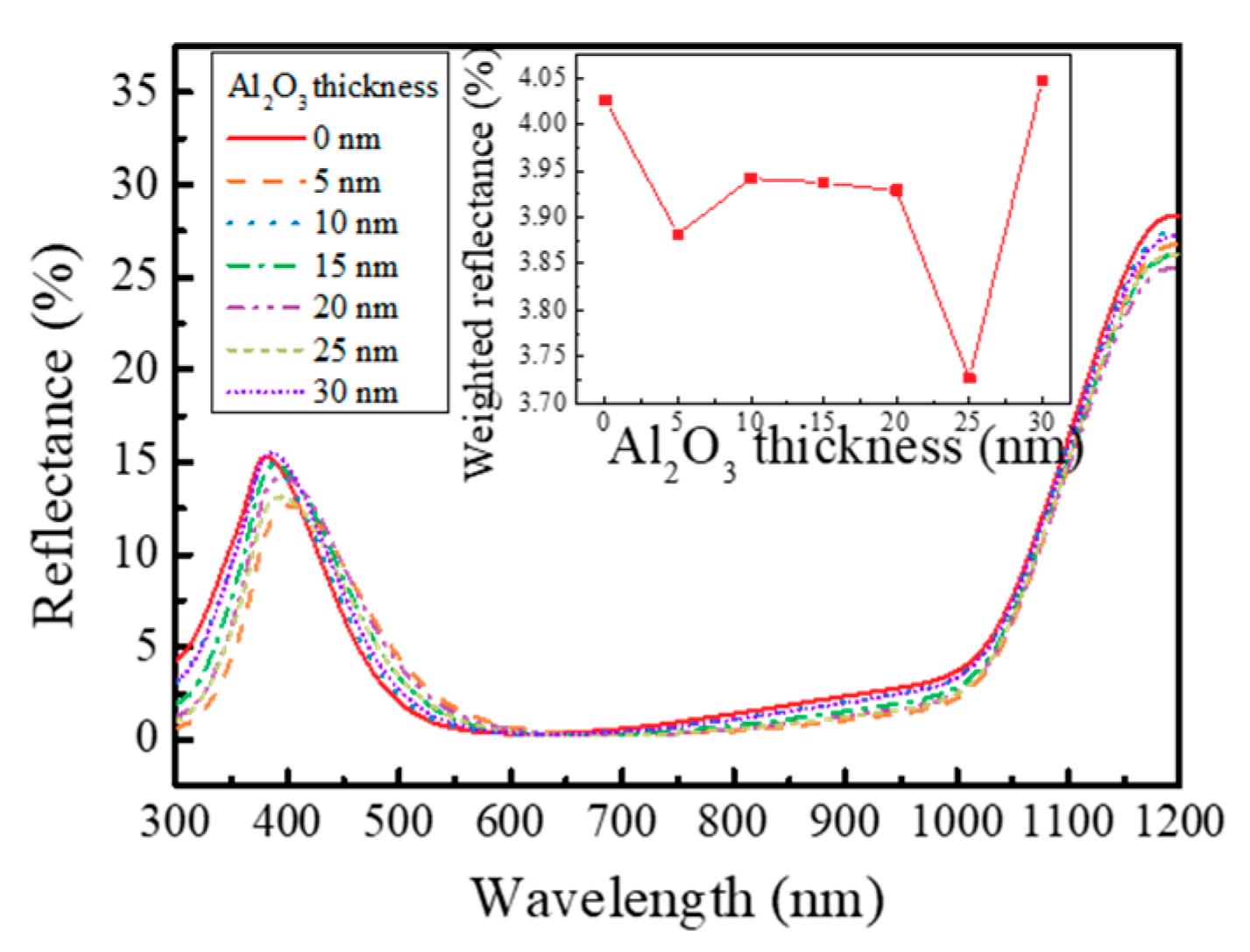
In order to investigate the influence of Al
2O
3 ARC, reflectance was first measured, and the weighted reflectance was calculated from the measured reflectance because it was used to estimate the feasibility of the ARCs with respect to the intensity of solar irradiation [
5]. Measured reflectance and weighted reflectance according to Al
2O
3 thickness are shown in
Figure 5. The results of the reflectance measurements were similar to the simulation results. Reflectance in the wavelength range from ~400 nm to 600 nm increased, but it decreased at shorter and longer wavelengths ranges, as shown in
Figure 5. As thickness of Al
2O
3 was increased, the increase and decrease in reflectance were enhanced. The inset figure in
Figure 5 shows the calculated weighted reflectance depending on the thickness of Al
2O
3, indicating that the weighted reflectance was decreased from 4.03% to 3.72% at Al
2O
3 thickness of 25 nm. However, the weighted reflectance increased to 4.05% when the thickness of the deposited Al
2O
3 layer was increased to 30 nm. These reflectance changes were seen because the total reflectance with respect to the wavelength changed by the deposition Al
2O
3, which corresponded with the simulation result.
To investigate the effect of Al
2O
3 on SHJ solar cell parameter directly, we measured EQE, J
SC, V
OC, and FF before and after Al
2O
3 deposition. The EQEs with Al
2O
3 layer thicknesses of 5, 10, 15, 20, 25, and 30 nm from 300 to 1100 nm are shown in
Figure 6. Commonly, we observed that reflectance decreased at wavelengths from ~420 nm to 600 nm and increased at longer and shorter wavelengths. By comparing
Figure 5 and
Figure 6, the wavelength range, which manifested the improved EQE, was similar with the wavelength range where reflectance was decreased for all solar cells. Accordingly, we observed the change of the reflectance by deposition of Al
2O
3 which was similar with the simulation results, indicating that it can improve the efficiency. In order to investigate the influence of Al
2O
3 ARC directly, the SHJ solar cell parameters before and after deposition of Al
2O
3 are summarized in
Table 1. J
SC of the cell with a 5 nm-thick Al
2O
3 layer was 1.0 mA/cm
2 higher than J
SC of the cell prior to Al
2O
3 deposition. Compared to the J
SC of cells prior to Al
2O
3 deposition, J
SC of the cells with Al
2O
3 layers 10, 15, 20, 25, and 30 nm thick was higher by 1.25, 1.0, 1.5, 1.25, and 1.25 mA/cm
2, respectively. Thus, the J
SC of all cells was increased by deposition of Al
2O
3. The highest increase of 1.5 mA/cm
2 in J
SC was observed when 20 nm-thick Al
2O
3 was deposited on SHJ solar cell. Compared to HfO
2 and IZO layer on ITO, it showed an increased J
SC of 0.84 and 1 mA/cm
2. As a result, we obtain the highest improvement in the efficiency from 22% to 23% by deposition of a 20 nm-thick Al
2O
3 on SHJ solar cell.
Figure 7 shows the current–voltage (I–V) curve of the SHJ solar cell before and after the Al
2O
3 deposition, indicating that the J
SC increased after the Al
2O
3 deposition.


