Communication

The Performance of Orbital Angular Momentum Mode (|l| = 1~3) Amplification Based on Ring-Core Erbium-Doped Fibers

Key Laboratory of Specialty Fiber Optics and Optical Access Networks, Joint International Research Laboratory of Specialty Fiber Optics and Advanced Communication, Shanghai Institute for Advanced Communication and Data Science, Shanghai University, Shanghai 200444, China
*
Author to whom correspondence should be addressed.
Photonics 2022, 9(7), 491; https://doi.org/10.3390/photonics9070491
Submission received: 10 June 2022 / Revised: 5 July 2022 / Accepted: 10 July 2022 / Published: 13 July 2022
(This article belongs to the Topic Fiber Optic Communication)

Abstract

:
We demonstrated that a ring-core erbium-doped fiber amplifier (RC-EDFA) can support orbital angular momentum (OAM) modes with topological charges (|l| = 1~3). The dependence of the characteristics on the length of the RC-EDF was investigated experimentally, including an investigation of gain and 3 dB gain bandwidth over the whole C band (i.e., 1530~1565 nm). The 3 dB gain bandwidth was improved to 21 nm. At a signal wavelength of 1550 nm, the maximum gain of all signal modes was up to 30.1 dB. Differential modal gain was maintained below approximately 1.3 dB.

1. Introduction

The information capacity of single-mode fibers (SMFs) needed to satisfy the growing demand for data traffic is approaching its physical limits, which is known as “capacity crunch” [1,2]. In order to solve this problem, mode-division multiplexing (MDM) has been intensively investigated [3,4,5]. Orbital angular momentum (OAM) has provided new MDM technology for the purpose of increasing the information capacity of optical fiber communication [6,7,8] due to its theoretically infinite topological charge. The multiplexed and demultiplexed technologies have been extended, owing to the orthogonal characteristics between different OAM modes. OAM modes are subject to external environments in free space. Hence, different types of specialty fibers supporting OAM modes have been studied, including air-core fibers [9], ring-core fibers (RCFs) [10,11,12,13], photonic crystal fibers [14,15], and multi-mode fibers (MMFs) [16]. Remarkably, since the refractive-index distribution of the RCFs with a high refractive-index ring-core matches the intensity distribution of OAM modes, RCFs are mostly used to support the stable transmission of OAM modes.
Optical amplifiers play a critical role in long-distance transmission networks [17,18]. In particular, the use of erbium-doped fiber amplifiers (EDFAs) for OAM modes has attracted considerable attention [19,20]. Early works on the amplification of the OAM mode demonstrated a topological charge of |l| = 1 or 2 [21]. The modal gain of the OAM-EDFA of up to 15.7 dB has been realized, but this needs to be further improved to meet the transmission demand. In addition, higher-order OAM-EDFAs can carry more OAM modes than lower-order ones. The number of OAM modes has been extended for higher-order OAM mode amplification based on ring-core erbium-doped fibers (RC-EDFs), and their gain has been improved to 19 dB over the C band [22]. The effect of fiber length on the gain of RC-EDFs at a wavelength of 1550 nm has been theoretically simulated. However, the optimal length of RC-EDFs at different signal wavelengths is different due to the reabsorption effect. The length of RC-EDFs has a significant impact on gain and 3 dB gain bandwidth over the whole C band (i.e., 1530~1565 nm) [23]. Thus, the optimization of the RC-EDF length in the ring-core erbium-doped fiber amplifier (RC-EDFA) should be considered comprehensively.
In this study, we investigated an RC-EDF that was capable of the amplification of OAM modes (|l| = 1~3) over the C band. The effect of the RC-EDF length on gain and 3 dB gain bandwidth were discussed in detail. The gain spectral peak was red-shifted as the RC-EDF length increased due to the reabsorption effect. A 3 dB gain bandwidth was improved to 21 nm. Furthermore, the maximum modal gain of up to 30.1 dB at a signal wavelength of 1550 nm was also obtained. The differential modal gain (DMG) was maintained below approximately 1.3 dB.

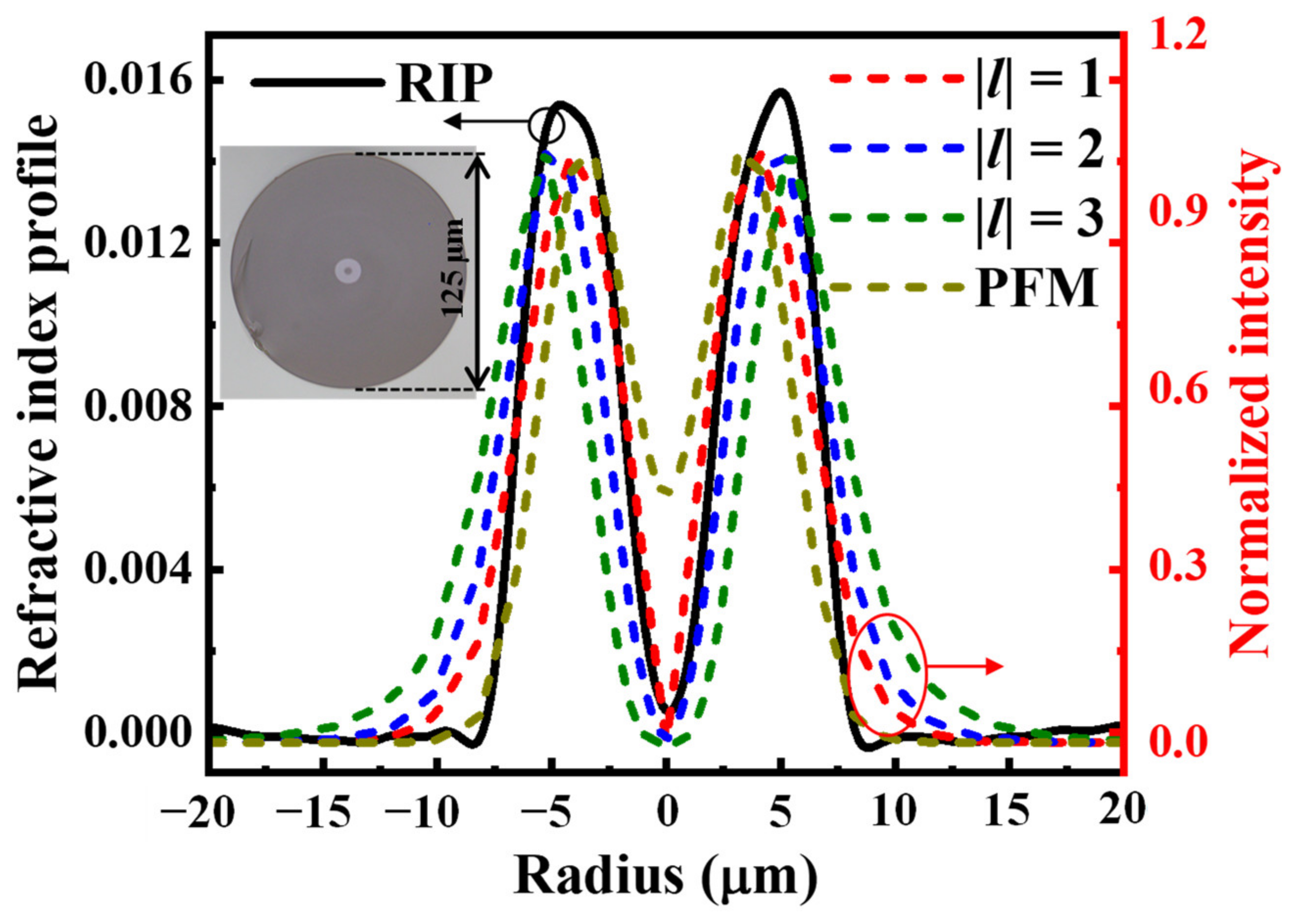
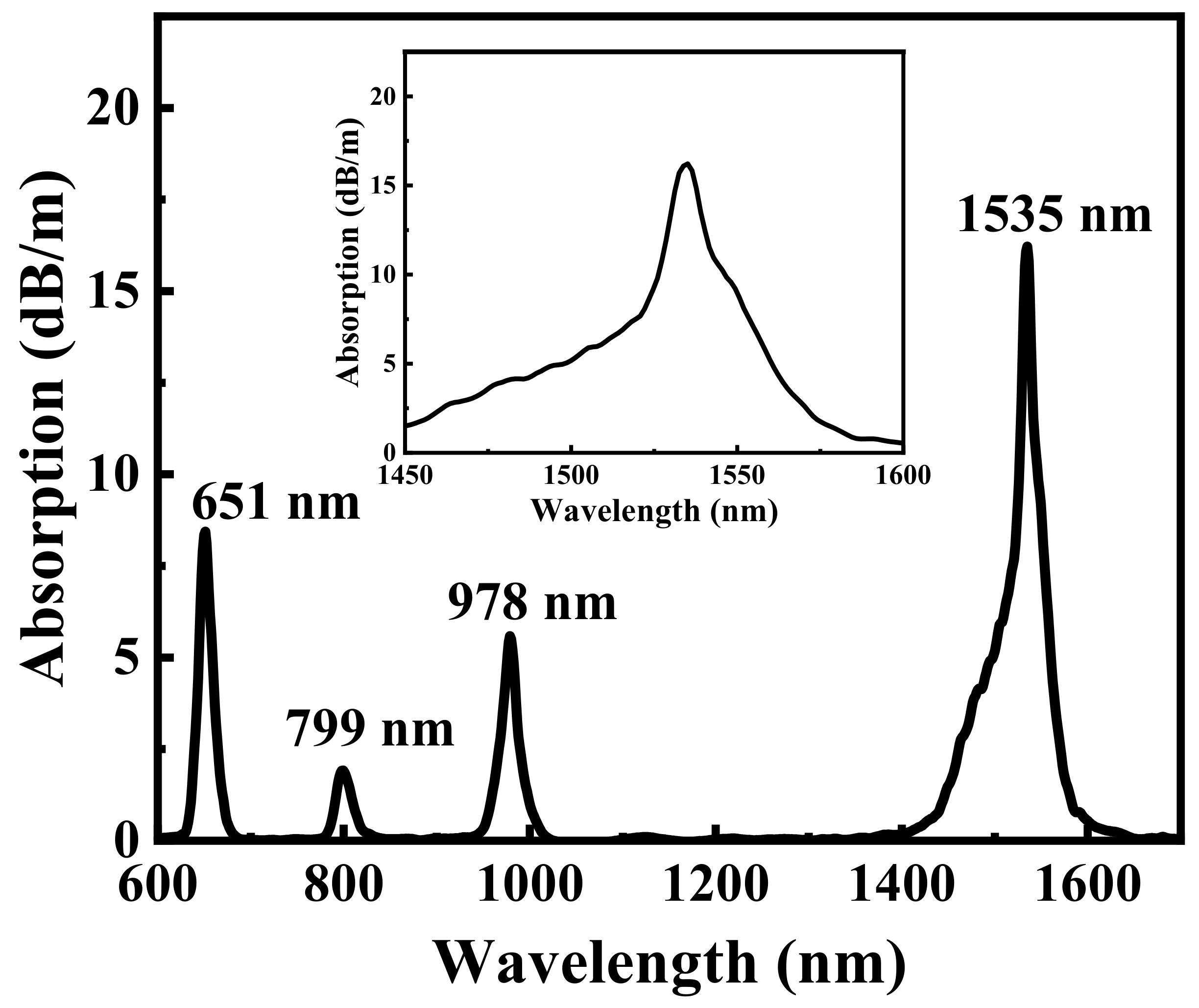
2. Characterization of the Ring-Core Erbium-Doped Fibers for OAM Modes

The proposed RC-EDF is composed of a central ring-core and cladding. Figure 1 shows the relative refractive-index profile (RIP) of the RC-EDF, as well as a cross-sectional image of the RC-EDF obtained using a microscope. The RC-EDF has a cladding diameter of 125 μm, an inner ring-core diameter of 4.1 μm, and a ring-core thickness of 4.9 μm. There is a large refractive-index difference between the ring-core and the cladding of 0.015, which might ensure that the RC-EDF can support OAM modes (|l| = 1~3).
According to the measured RIP, the modal characteristics of the RC-EDF were numerically simulated using the finite-element method (COMSOL Multiphysics® software). The effective refractive-indexes of the guided modes were plotted as a function of wavelength, as shown in Figure 2. The RC-EDF could support three groups of high-order OAM modes (|l| = 1~3) in the C band. The effective index differences between the OAM mode groups were much larger than 10−3. It was proven that the crosstalk among these OAM mode groups could be effectively suppressed [24].
In addition, the modal intensity profiles of the OAM modes (|l| = 1~3) at the 1550 nm level and pump fundamental mode (PFM) were also calculated, as shown in Figure 1. Attributed to the graded index, the OAM mode groups were more concentrated within the ring-core. The erbium doping profile in the RC-EDF was consistent with the refractive-index profile. The overlapping factors between the i-th OAM mode signal and the PFM can be defined as [25]:
Γ = 0 2 π r 1 r 2 I s r , φ I p r , φ N 0 r , φ r d r d φ
where I s r , φ is the normalized intensity profile of the i-th OAM mode signal; I p r , φ is the normalized intensity profile of the PFM; N 0 r , φ is the total erbium ion density; and r 1 and r 2 are the inner and outer radii of the erbium doping area, respectively.
Hence, the overlapping factors between the signal OAM modes (|l| = 1~3) and PFM are 1.32 × 10¹⁸, 0.98 × 10¹⁸ and 0.69 × 10¹⁸, respectively. This indicates that the RC-EDF could achieve a greater gain and lower DMG [22].
The small-signal absorption spectrum of the RC-EDF was measured using an optical spectrum analyzer (OSA, AQ6370D) and a white-light source by employing the cutback method [26], as shown in Figure 3. The absorption spectrum in the wavelength range of 1450 nm to 1600 nm was enlarged, as shown in the inset of Figure 3. The RC-EDF was spliced with SMFs and MMFs (62.5/125 μm) at its input and output ends, respectively. It exhibited four absorption bands: approximately 8.43 dB/m at the 651 nm level, 1.90 dB/m at the 799 nm level, 5.58 dB/m at the 978 nm level, and 16.21 dB/m at the 1535 nm level. These bands are consistent with the classical absorption bands of erbium ions [27], corresponding to 4I15/24F9/2, 4I9/2, 4I11/2, and 4I13/2, respectively. In addition, the background loss at the 1310 nm level was 0.03 dB/m. Compared with the single-mode EDF, the loss of the RC-EDF was larger at the absorption peak of 1535 nm owing to the higher concentration of erbium ions in the fiber, which facilitates high-efficiency optical amplification.

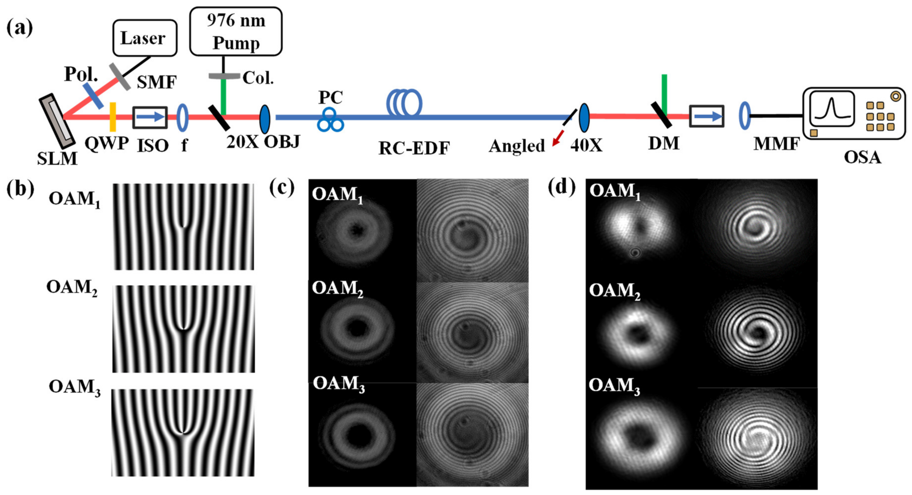
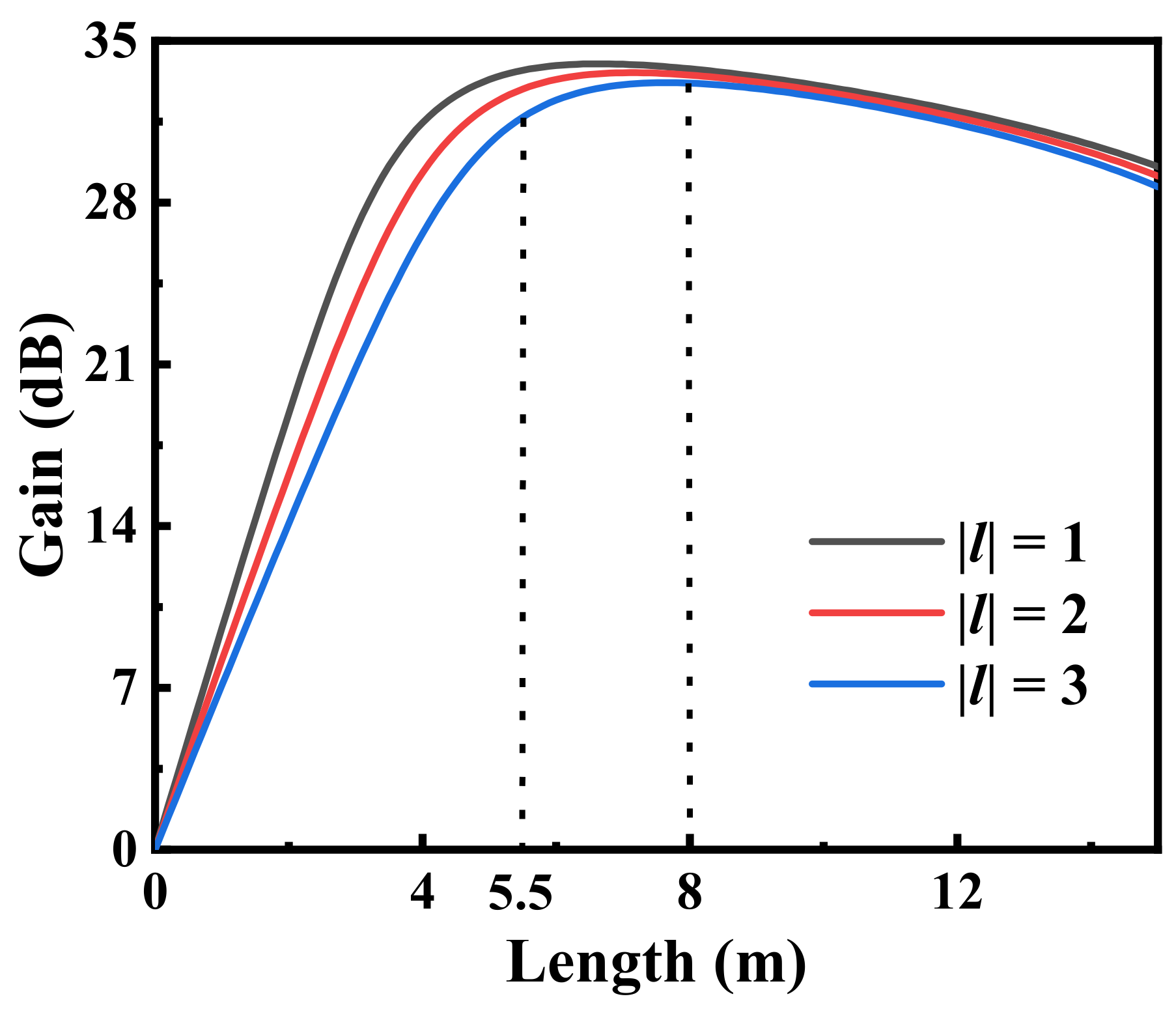
3. Experimental Setup and Results

Figure 4a shows a schematic of the RC-EDFA, which amplifies the OAM signal modes (|l| = 1~3) using a core-pumping configuration. It consists of three main parts for the generation, amplification, and detection of OAM modes. A single OAM mode is selectively excited using a spatial light modulator (SLM). The signal and pump lights are multiplexed via a dichroic mirror (DM), which has a high transmission of signal light in the C band, as well as a high reflection of the 976 nm pump light. Conversely, the signal and residual pump lights are separated by another DM at the output of the RC-EDF. The RC-EDF is used as the active gain medium. The input end of the RC-EDF is flat-cleaved to ensure the high-efficiency excitation of the OAM modes, while the output end of the RC-EDF is angle-cleaved to avoid Fresnel reflection. Two free-space isolators are placed at both ends of the RC-EDF to prevent light reflection from entering the amplifier and to improve the stability of the amplifier. The OSA is used to measure the input and output spectra for calculating real-time amplified stimulated emission (ASE) intensity. The forked diffraction gratings loaded onto the SLM to generate OAM modes with topological charges (|l| = 1~3) are described in Figure 4b. An infrared camera is employed to detect the input and output beam profiles of the RC-EDF. Figure 4c shows clean OAM intensity profiles generated by the SLM and the corresponding interference patterns. The output beam profiles of the OAM (|l| = 1~3) in the RC-EDF are captured. In Figure 4d, the intensity distribution of the donut in the OAM beam with phase singularity and the OAM interferograms formed by the interference between the OAM mode beam and the reference Gaussian beam can also be observed. The results confirm that the clean OAM mode could be excited and transmitted stably in the RC-EDF.
In this research, the modal gains, as a function of the RC-EDF length, were simulated at the 1550 nm level using the rate and light propagation equations as a foundation [28,29], as shown in Figure 5. The conditions in the simulation were as follows: (1) the signal power was −12.7 dBm; (2) the pump power was 800 mW; and (3) the erbium doping concentration was 1.3 × 1025 m−3. It can be seen that modal gains increased with the increased in the RC-EDF length at the beginning, while the modal gains gradually tended to decrease with the further increase in the RC-EDF length. This is due to the depleted population inversion caused by the increasing signal power. Theoretical analyses and numerical simulations illustrated that the optimal modal gains (|l| = 1~3) could be obtained in the RC-EDF length range of 5.5~8 m. The maximum modal gains could be larger than 33 dB.
The effect of the RC-EDF length on the amplification characteristics was investigated in the experiment. The spectra of the amplified OAM modes based on RC-EDFs of different lengths were measured at a launched pump power of 800 mW and an input signal power of −12.7 dBm. Eight wavelength channels were spaced equally from 1530 to 1565 nm. The OAM modes (|l| = 1~3) have similar amplification characteristics. In order to investigate the effect of the RC-EDF length on amplification characteristics, the highest-order (|l| = 3) OAM mode was taken as a typical mode. Figure 6 presents the measured gain spectra of the OAM mode (|l| = 3) for eight different fiber lengths with respect to the wavelength to achieve clarity. Since the erbium doping distribution of the fabricated RC-EDF was not as uniform as it was in the simulation, the actual gain was not as high as it was in the simulation. The gain peak became blue-shifted as the RC-EDF length decreased. The gain peaked at the 1560 nm level for the L = 11.5 m RC-EDF. The gain peak shifted toward 1550 nm when the RC-EDF length was reduced to 6.5 m. When the length was further reduced to 5.5 m, the gain peak shifted to the 1535 nm level. However, the gain peak did not remain blue-shifted as the RC-EDF length further decreased due to the effects of an absorption band in the RC-EDF at the 1535 nm level. As the length was further reduced to 4.5 m, the gains over the whole C band decreased overall. In addition, the gain difference between the 1530 and 1565 nm levels was approximately 24.4 dB for the 11.5 m RC-EDF. The gain imbalance was significantly improved as the RC-EDF length was shortened, owing to the reduction in the reabsorption effect and absorption. With the 11.5 m RC-EDF, the amplified power was lower than the absorbed power was at the 1530 nm level, which resulted in a negative net gain due to the reabsorption effect [30]. This means that the amplified power under the excessively long RC-EDF was strongly reabsorbed due to the Er3+ absorption band at around the 1535 nm level.
In order to exhibit the spectral amplification properties of the RC-EDF, a series of amplified signal wavelengths in the third-order OAM mode were measured with the RC-EDF length of 5.5 m; these are plotted together in Figure 7a. The spectra of the amplified OAM modes were flat. The other two lower-order OAM modes manifested similar spectral amplification properties. Figure 7b presents the gains and DMGs of the OAM modes (|l| = 1~3) versus the signal wavelength. It can be seen that there is a minimum modal gain of 19.9 dB across the whole C band. Obviously, the DMGs per wavelength in the C band were lower than 1.3 dB. The gains of the three OAM mode groups were highly coincident. Therefore, the fabricated RC-EDF has a natural advantage in differential modal gain equalization.
The amplification characteristics with respect to the RC-EDF length were further investigated concerning the 3 dB gain bandwidth, which is also one of the important indicators for evaluating the performance of EDFAs. Figure 8 shows the 3 dB gain bandwidth for different RC-EDF lengths. The overall trend was non-monotonic, and the bandwidth became wider as the fiber length increased. In particular, a 6.5 m RC-EDF resulted in a flatter gain spectrum for which the 3 dB gain bandwidth was increased to 21 nm, spanning from 1541 to 1562 nm. The 3 dB gain bandwidth decreased with an increase in the RC-EDF length from 6.5 to 7.5 m due to the effects of increased absorption with the excessively long RC-EDF. By further increasing the RC-EDF length, the absorption at the short wavelengths would allow the gain at the long wavelengths due to the reabsorption effect. The 3 dB gain bandwidth decreased with a reduction in the fiber length from 6.5 to 4.5 m, which was due to the protuberant gain peak at the 1535 nm level. If a traditional gain equalizer were utilized—for example, long-period gratings [31]—a far broader gain spectrum could be obtained.
The dependence of the gain on the signal power and pump power was tested at the 1550 nm level using the 6.5 m RC-EDF. Figure 9a presents the modal gains (|l| = 1~3) with respect to the pump power at a signal wavelength of 1550 nm and the signal power of −24 dBm. The gain increased gradually with an increase in the pump power and tended towards saturation when the pump power exceeded 600 mW. The modal gains (|l| = 1~3) with respect to the signal power at the 1550 nm level were also measured, as shown in Figure 9b. The gain gradually decreased as the signal power increased. The maximum gains of OAM modes were measured to be up to 30.1 dB. The maximum output power levels were measured to be up to 14.5 dBm.

4. Conclusions

We proposed an amplifier based on an RC-EDF for three OAM mode groups (|l| = 1~3). The amplification characteristics of these OAM modes in the RC-EDFs over the C band were experimentally evaluated. The dependence on length of the RC-EDFA was investigated including gain and 3 dB gain bandwidth. The 3 dB gain bandwidth was 21 nm. The maximum modal gains were up to 30.1 dB, and the DMGs were maintained below approximately 1.3 dB. The performance of the OAM-mode amplification technique based on RC-EDFs could be further investigated by optimizing the pump modes. The setup would be further modified to consider the effect of mode crosstalk on the performance of the RC-EDFA. The proposed RC-EDFA could support long-distance and large-capacity fiber communications in the future.

Author Contributions

Conceptualization, S.L. and F.P.; methodology, S.L. and F.P.; software, S.L. and F.P.; validation, L.Z., J.W., W.C. and T.W.; formal analysis, Q.J. and X.X.; investigation, S.L.; data curation, Q.J. and X.X; writing—original draft preparation, S.L.; writing—review and editing, F.P. All authors have read and agreed to the published version of the manuscript.

Funding

This research was funded by the National Key Research and Development Program of China, grant number 2018YFB1801800 and the National Natural Science Foundation of China, grant number 61635006, 61975113.

Institutional Review Board Statement

Not applicable.

Informed Consent Statement

Not applicable.

Data Availability Statement

Not applicable.

Conflicts of Interest

The authors declare no conflict of interest.

References

  1. Essiambre, R.J.; Foschini, G.J.; Kramer, G.; Winzer, P.J. Capacity Limits of Information Transport in Fiber-Optic Networks. Phys. Rev. Lett. 2008, 101, 163901. [Google Scholar] [CrossRef] [PubMed]
  2. Richardson, D.J.; Fini, J.M.; Nelson, L.E. Space-Division Multiplexing in Optical Fibres. Nat. Photonics 2013, 7, 354–362. [Google Scholar] [CrossRef] [Green Version]
  3. Van Uden, R.G.H.; Correa, R.A.; Lopez, E.A.; Huijskens, F.M.; Xia, C.; Li, G.; Schulzgen, A.; de Waardt, H.; Koonen, A.M.J.; Okonkwo, C.M. Ultra-High-Density Spatial Division Multiplexing with a Few-Mode Multicore Fibre. Nat. Photonics 2014, 8, 865–870. [Google Scholar] [CrossRef] [Green Version]
  4. Chen, H.; Jin, C.; Huang, B.; Fontaine, N.K.; Ryf, R.; Shang, K.; Gregoire, N.; Morency, S.; Essiambre, R.J.; Li, G.; et al. Integrated Cladding-Pumped Multicore Few-Mode Erbium-Doped Fibre Amplifier for Space-Division-Multiplexed Communications. Nat. Photonics 2016, 10, 529–533. [Google Scholar] [CrossRef] [Green Version]
  5. Rademacher, G.; Luis, R.S.; Puttnam, B.J.; Eriksson, T.A.; Ryf, R.; Agrell, E.; Maruyama, R.; Aikawa, K.; Awaji, Y.; Furukawa, H.; et al. High Capacity Transmission with Few-Mode Fibers. J. Lightwave Technol. 2019, 37, 425–432. [Google Scholar] [CrossRef] [Green Version]
  6. Wang, J.; Yang, J.Y.; Fazal, I.M.; Ahmed, N.; Yan, Y.; Huang, H.; Ren, Y.X.; Yue, Y.; Dolinar, S.; Tur, M.; et al. Terabit Free-Space Data Transmission Employing Orbital Angular Momentum Multiplexing. Nat. Photonics 2012, 6, 488–496. [Google Scholar] [CrossRef]
  7. Bozinovic, N.; Yue, Y.; Ren, Y.X.; Tur, M.; Kristensen, P.; Huang, H.; Willner, A.E.; Ramachandran, S. Terabit-Scale Orbital Angular Momentum Mode Division Multiplexing in Fibers. Science 2013, 340, 1545–1548. [Google Scholar] [CrossRef] [Green Version]
  8. Ma, Z.L.; Ramachandran, S. Propagation Stability in Optical Fibers: Role of Path Memory and Angular Momentum. Nanophotonics 2021, 10, 209–224. [Google Scholar] [CrossRef]
  9. Gregg, P.; Kristensen, P.; Ramachandran, S. Conservation of Orbital Angular Momentum in Air-Core Optical Fibers. Optica 2015, 2, 267–270. [Google Scholar] [CrossRef] [Green Version]
  10. Ramachandran, S.; Gregg, P.; Kristensen, P.; Golowich, S.E. On the Scalability of Ring Fiber Designs for Oam Multiplexing. Opt. Express 2015, 23, 3721–3730. [Google Scholar] [CrossRef]
  11. Rojas-Rojas, S.; Canas, G.; Saavedra, G.; Gomez, E.S.; Walborn, S.P.; Lima, G. Evaluating the Coupling Efficiency of Oam Beams into Ring-Core Optical Fibers. Opt. Express 2021, 29, 23381–23392. [Google Scholar] [CrossRef] [PubMed]
  12. Zhu, L.; Wang, A.D.; Chen, S.; Liu, J.; Mo, Q.; Du, C.; Wang, J. Orbital Angular Momentum Mode Groups Multiplexing Transmission over 2.6-Km Conventional Multi-Mode Fiber. Opt. Express 2017, 25, 25637–25645. [Google Scholar] [CrossRef] [PubMed]
  13. Fang, Y.H.; Zeng, Y.; Qin, Y.W.; Xu, O.; Li, J.P.; Fu, S.N. Design of Ring-Core Few-Mode-Edfa with the Enhanced Saturation Input Signal Power and Low Differential Modal Gain. IEEE Photonics J. 2021, 13, 1–6. [Google Scholar] [CrossRef]
  14. Deng, Y.F.; Zhang, H.; Li, H.; Tang, X.F.; Xi, L.X.; Zhang, W.B.; Zhang, X.G. Erbium-Doped Amplification in Circular Photonic Crystal Fiber Supporting Orbital Angular Momentum Modes. Appl. Opt. 2017, 56, 1748–1752. [Google Scholar] [CrossRef]
  15. Fujisawa, T.; Saitoh, K. Arbitrary Polarization and Orbital Angular Momentum Generation Based on Spontaneously Broken Degeneracy in Helically Twisted Ring-Core Photonic Crystal Fibers. Opt. Express 2021, 29, 31689–31705. [Google Scholar] [CrossRef]
  16. Wang, A.D.; Zhu, L.; Wang, L.L.; Ai, J.Z.; Chen, S.; Wang, J. Directly Using 8.8-Km Conventional Multi-Mode Fiber for 6-Mode Orbital Angular Momentum Multiplexing Transmission. Opt. Express 2018, 26, 10038–10047. [Google Scholar] [CrossRef]
  17. Zhang, Z.Z.; Guo, C.; Cui, L.; Zhang, Y.C.; Du, C.; Li, X.Y. All-Fiber Few-Mode Erbium-Doped Fiber Amplifier Supporting Six Spatial Modes. Chin. Opt. Lett 2019, 17, 118–122. [Google Scholar] [CrossRef]
  18. Matte-Breton, C.; Chen, H.; Fontaine, N.K.; Ryf, R.; Essiambre, R.J.; Kelly, C.; Jin, C.; Messaddeq, Y.; LaRochelle, S. Demonstration of an Erbium-Doped Fiber with Annular Doping for Low Gain Compression in Cladding-Pumped Amplifiers. Opt. Express 2018, 26, 26633–26645. [Google Scholar] [CrossRef]
  19. Ma, J.W.; Xia, F.; Chen, S.; Li, S.H.; Wang, J. Amplification of 18 OAM Modes in a Ring-Core Erbium-Doped Fiber with Low Differential Modal Gain. Opt. Express 2019, 27, 38087–38097. [Google Scholar] [CrossRef]
  20. Lin, D.; Carpenter, J.; Feng, Y.T.; Jung, Y.M.; Alam, S.U.; Richardson, D.J. High-Power, Electronically Controlled Source of User-Defined Vortex and Vector Light Beams Based on a Few-Mode Fiber Amplifier. Photonics Res. 2021, 9, 856–864. [Google Scholar] [CrossRef]
  21. Jung, Y.M.; Kang, Q.Y.; Sidharthan, R.; Ho, D.; Yoo, S.; Gregg, P.; Ramachandran, S.; Alam, S.U.; Richardson, D.J. Optical Orbital Angular Momentum Amplifier Based on an Air-Hole Erbium-Doped Fiber. J. Lightwave Technol. 2017, 35, 430–436. [Google Scholar] [CrossRef] [Green Version]
  22. Wen, T.J.; Gao, S.C.; Li, W.; Tu, J.J.; Du, C.; Zhou, J.; Ao, Z.H.; Zhang, B.; Liu, W.P.; Li, Z.H. Third- and Fourth-Order Orbital Angular Momentum Multiplexed Amplification with Ultra-Low Differential Mode Gain. Opt. Lett. 2021, 46, 5473–5476. [Google Scholar] [CrossRef] [PubMed]
  23. Melkumov, M.A.; Bufetov, I.A.; Shubin, A.V.; Firstov, S.V.; Khopin, V.F.; Guryanov, A.N.; Dianov, E.M. Laser Diode Pumped Bismuth-Doped Optical Fiber Amplifier for 1430 nm Band. Opt. Lett. 2011, 36, 2408–2410. [Google Scholar] [CrossRef] [PubMed]
  24. Ramachandran, S.; Kristensen, P. Optical Vortices in Fiber. Nanophotonics 2013, 2, 455–474. [Google Scholar] [CrossRef]
  25. Bigot, L.; Le Cocq, G.; Quiquempois, Y. Few-Mode Erbium-Doped Fiber Amplifiers: A Review. J. Lightwave Technol. 2015, 33, 588–596. [Google Scholar] [CrossRef]
  26. Dissanayake, K.P.W.; Abdul-Rashid, H.A.; Safaei, A.; Oresegun, A.; Shahrizan, N.; Omar, N.Y.M.; Yusoff, Z.; Zulkifli, M.I.; Muhamad-Yassin, S.Z.; Mat-Sharif, K.A.; et al. Fabrication and Characterization of a Gallium Co-Doped Erbium Optical Fiber. In Proceedings of the 2014 IEEE 5th International Conference on Photonics (ICP), Kuala Lumpur, Malaysia, 2–4 September 2014; pp. 113–115. [Google Scholar]
  27. Yamasaki, Y.; Azuma, R.; Kagebayashi, Y.; Fujioka, K.; Fujimoto, Y. Optical Properties of Er3+ Heavily Doped Silica Glass Fabricated by Zeolite Method. J. Non. Cryst. Solids. 2020, 543, 120149. [Google Scholar] [CrossRef]
  28. Kang, Q.Y.; Gregg, P.; Jung, Y.M.; Lim, E.L.; Alam, S.U.; Ramachandran, S.; Richardson, D.J. Amplification of 12 OAM Modes in an Air-Core Erbium Doped Fiber. Opt. Express 2015, 23, 28341–28348. [Google Scholar] [CrossRef] [Green Version]
  29. Ono, H.; Hosokawa, T.; Ichii, K.; Matsuo, S.; Nasu, H.; Yamada, M. 2-LP Mode Few-Mode Fiber Amplifier Employing Ring-Core Erbium-Doped Fiber. Opt. Express 2015, 23, 27405–27418. [Google Scholar] [CrossRef]
  30. Chen, S.P.; Li, Y.G.; Lu, K.C.; Zhou, H.; Liu, Z.J. High Power L-Band Erbium-Doped Fiber Laser Pumped by a C-Band Superfluorescent Source. Laser Phys. Lett. 2008, 5, 130–134. [Google Scholar] [CrossRef]
  31. Harumoto, M.; Shigehara, M.; Suganuma, H. Gain-Flattening Filter Using Long-Period Fiber Gratings. J. Lightwave Technol. 2002, 20, 1027–1033. [Google Scholar] [CrossRef]
Figure 1. Measured RIP of the RC-EDF and normalized intensity profiles of OAM modes (|l| = 1~3) of the RC-EDF the at 1550 nm level and PFM at the 976 nm level (inset: cross-sectional microscopic image).
Photonics 09 00491 g001
Figure 2. Modal effective-refractive index with respect to the wavelength of the RC-EDF.
Photonics 09 00491 g002
Figure 3. Measured absorption spectrum of the RC-EDF (inset: enlarged absorption spectrum in the wavelength range of 1450 to 1600 nm).
Photonics 09 00491 g003
Figure 4. (a) Schematic of the RC-EDFA: SLM, spatial light modulator; Pol., polarizer; QWP, quarter-wave plate; SMF, single-mode fiber; ISO, isolator; f, lens; Col., Collimator; OBJ, objective lens; PC, polarization controller; RC-EDF, ring-core erbium-doped mode fiber; DM, dichroic mirror; MMF, multi-mode fiber; OSA, optical spectrum analyzer. (b) The phase patterns used to generate the OAM modes (|l| = 1~3). (c) The intensity distribution and interference patterns of the OAM modes generated by the SLM. (d) Experimental results of output intensity profiles of OAM modes and corresponding output interference patterns.
Photonics 09 00491 g004
Figure 5. Simulated modal gains as a function of RC-EDF length at the 1550 nm level.
Photonics 09 00491 g005
Figure 6. Measured gain spectra for eight different fiber lengths with respect to the signal wavelength.
Photonics 09 00491 g006
Figure 7. (a) Measured amplified spectra for 5.5 m RC-EDF with respect to the signal wavelength; (b) measured modal gains and DMGs with respect to the signal wavelength.
Photonics 09 00491 g007
Figure 8. The 3 dB gain bandwidth with respect to the RC-EDF length.
Photonics 09 00491 g008
Figure 9. (a) Measured modal gains of a 6.5 m RC-EDF with respect to the pump power at the 1550 nm level; (b) the measured modal gains of a 6.5 m RC-EDF with respect to the signal power at the 1550 nm level.
Photonics 09 00491 g009
Publisher’s Note: MDPI stays neutral with regard to jurisdictional claims in published maps and institutional affiliations.

