Article

Design and Performance Analysis of Hybrid Multidimensional OAM-DM-WDM-OFDM-PON System with High-Capacity and Long-Distance Transmission

1
College of Electronic and Information Engineering, Shandong University of Science and Technology, 579 Front Bay Harbour Road, Qingdao 266590, China
2
School of Information Science and Engineering, Shandong University, 72 Binhai Road, Jimo District, Qingdao 266237, China
*
Author to whom correspondence should be addressed.
Photonics 2022, 9(7), 448; https://doi.org/10.3390/photonics9070448
Submission received: 24 May 2022 / Revised: 23 June 2022 / Accepted: 24 June 2022 / Published: 27 June 2022
(This article belongs to the Topic Fiber Optic Communication)

Abstract

:
Orbital angular momentum (OAM) with mutually orthogonal advantage attribute to break through the high capacity and long-reach transmission limited in the classical passive optical network (PON). Employing Laguerre Gaussian (LG) mode as the orthogonal OAM excitation, a more dimensional multiplexing PON system is proposed to creatively hybridize OAM division multiplexing (OAM-DM) based on wavelength division multiplexing (WDM) and orthogonal frequency division multiplexing (OFDM). By utilizing the compatibility of OAM-DM and WDM, data of 40 Gbit/s OFDM signals is successfully transmitted in 80 km multimode fiber (MMF) with low crosstalk. Within this hybrid system, the effects of different wavelengths and different modes on the bit error rate (BER) are discussed at varying transmission distances. Moreover, the performance of several subsystems carrying quadrature phase-shift keying (QPSK), on-off keying (OOK), and OFDM modulation signals is also compared at a BER less than 3.8 × 10 3 . It is observed that the proposed OAM-DM-WDM-OFDM-PON system has favorable performance, which is a reasonable solution for large-capacity PON architecture.

1. Introduction

Passive optical network (PON) has been widely applied in fiber to the x (FTTx) services owing to its low cost and low energy consumption [1]. In comparison with traditional PON architecture, next-generation PON (NG-PON) has the advantages of expanding network coverage and increasing data rate. Typically, NG-PON mainly includes time wavelength division multiplexing PON (TWDM-PON) [2], wavelength division multiplexing PON (WDM-PON) [3,4], orthogonal frequency-division multiplexing PON (OFDM-PON) [5], etc. Among these techniques, WDM-PON has attracted much attention due to its high bandwidth, large capacity, and channel independence [6]. However, as the traditional photon dimension resources are exhausted, the new capacity crisis of optical communication begins to appear. Facing the explosive growth of global data traffic, it is urgent to design a more dimensional hybrid PON system for enhancing the transmission capacity.
Beyond the multiplexing technologies, numerous advanced modulation formats and multiplexing techniques such as OFDM, quadrature phase-shift keying (QPSK), on-off keying (OOK), and so on, have been reported. Unfortunately, the exploitation of the conventional dimension resources of the photon has reached a limitation. In addition to the known physical dimension (e.g., amplitude, phase, frequency/wavelength), the spatial structure of the light wave should be fully considered. Meanwhile, mode division multiplexing (MDM) using orthogonal spatial modes to load signals was an emerging technique for large-capacity data communication [7]. Recently, a lot of research works have been carried out on spatial modes in linearly polarized (LP) modes [8], orbital angular momentum (OAM) modes [9], and vector modes [10]. Particularly, LP and OAM modes are most widely used in MDM for efficiently increasing the capacity of the optical fiber link.
Allen et al. successfully revealed the property of Laguerre-Gaussian ( L G l p ) carrying OAM in 1992 [11]. Since then, OAM of light was a promising means for exploiting the spatial dimension of light to increase the communication capacity. However, the bottleneck to implement this technique relies on the generation and detection of OAM states, either inside free space optic (FSO) [12] or in optical fibers [13]. In addition, OAM is also used in optical imaging [14], quantum communication field [15], and so on. For OAM-FSO communication, Liu and Wang demonstrated OAM beams carrying four-level pulse-amplitude modulation (PAM-4) signal in FSO polarization-insensitive links [16]. Xie et al. proved that a data rate of 200 Gbps was achieved on a 1 m FSO link using two LG beams with different radial indexes [17]. Various MDM efforts have been focused on FSO links, but have little report devoted to optical fiber communication. Furthermore, the combination of OAM with polarization modulation (PM), OFDM, and other multi-dimensional modulation techniques is rarely considered in recent OAM optical fiber communication research. For OAM optical communication, a report on two-dimensional multiplexing of TDM and OAM was achieved in [18,19]. Yang et al. demonstrated the MDM-PON based on three-dimensional carrier-less amplitude/phase (3D-CAP) modulation that transmits over 4.1 km ring-core fiber (RCF) [20].
In this work, a more dimensional multiplexing OAM-DM-PON system, which combines WDM and OFDM is discussed in great detail to further improve the communication capacity of the access network. And the BER performance versus transmission distance is investigated. On the one hand, LG modes with different wavelengths are used to load OFDM signals at the transmitter side and a 10–80 km multimode fiber (MMF) for OAM multiplexing is required at the downstream transmission link. On the other hand, the case of a single OAM mode and a single wavelength system is examined and evaluated. Furthermore, the simulation results of three (OFDM, OOK, QPSK) modulation schemes with two LG modes multiplexing are also presented and compared. The simulation results verified that OAM is compatible with other dimensions of photons and can well meet the needs of high-capacity communication.

2. Principle

Three blocks are comprised in our OAM-DM link including LG mode generation, modulation, and multiplexing. Firstly, the orthogonal property of LG mode and OFDM modulation method are described theoretically. Figure 1 illustrates the transmitter structure of the hybrid OAM-DM-WDM-OFDM-PON system, where the OAM multiplexing is achieved by LG modes with different radial values. In fact, OAM and OFDM have been jointly used. Chen et al. proposed the 2D-FFT-based OAM-OFDM framework for broadband wireless communication [21]. As shown in Figure 1, the modulated two LG modes are multiplexed at the transmitter terminal, together with its 2D and 3D mode diagram.

2.1. LG Mode with Orthogonal Properties

The light field of the general vortex in polar coordinates is expressed as:
E ( r , θ , z ) = E 0 ( r , θ , z 0 ) exp ( i k z ) exp ( i l θ ) ,
where k is the wave vector. l is the azimuth value, E 0 ( r , θ , z 0 ) is the complex amplitude of incident light. z is the transmission distance.
After transmission for a certain distance, polar coordinates are converted to Cartesian coordinates and diffraction integrals are used, the amplitude of vortex beam is expressed as:
E ( x , y , z ) = i ( k 2 A z ) l + 1 ( y i x σ ) E 0 exp ( i k z ) exp [ i k z ( x 2 + y 2 ) / 2 σ 2 A z ] .
where A is light field amplitude. σ is the spot size.
It is well known that the most commonly used OAM beam is the LG beam, due to its simplicity of generation. The azimuth index is constant l = 0 and the radial indexes are p = 2   ,   4 , two L G l p modes are adopted in this study which can be described as [22]
u l p ( ρ , ϕ , z ) = B l p w ( z ) ( 2 ρ w ( z ) ) | l | exp ( ρ 2 w 2 ( z ) ) L p | l | ( 2 ρ 2 w 2 ( z ) ) exp ( i k 0 ρ 2 2 R ( z ) ) × exp [ i ( 2 p + | l | + 1 ) ζ ( z ) ] exp ( i l ϕ ) ,
where u l p ( ρ , ϕ , z ) represents light field intensity of the L G l p in a circularly symmetric form. B l p is the normalization constant which can be expressed as B l p = 2 p ! / [ π ( p + | l | ) ! ] . L p l ( ) is the generalized Laguerre polynomial. w ( z ) = w 0 1 + [ λ z / ( π w 0 2 ) ] 2 is the beam spot of L G l = 0 , p = 0 which w 0 is the radius of the beam waist. k 0 represents the wave vector of a light beam in a vacuum. R ( z ) equals to z i z R and z R is the Rayleigh range. ( 2 p + | l | + 1 ) ζ ( z ) is the Gouy phase shift with ζ ( z ) = tan 1 z / z R .
Moreover, the orthogonality of LG modes in the transmission is reflected if they have either a different p value or a different l value, which is expressed in cylindrical coordinates as [23]:
0 0 2 π u ( r , ϕ , l 1 , p 1 , w 0 ) u ( r , ϕ , l 2 , p 2 , w 0 ) d ϕ d r = { 0 , l 1 l 2   or   p 1 p 2   1 , l 1 = l 2   and   p 1 = p 2 ,
where l 1 and l 2 denote the topological charge. p 1 and p 2 are radial nodes. According to Equation (4), LG modes are mutually orthogonal only when l 1 l 2   or   p 1 p 2 , which offers a new degree for future communication systems.

2.2. OFDM Modulation

OFDM is a multi-carrier modulation technology and it uses multiple sub-carriers to convert the high-speed data streams to multiple sub-channels with relatively low rates for parallel transmission. Firstly, the data stream gets through the 4-QAM generator and OFDM modulator, as shown in Figure 1. Then, the OFDM signals are introduced into the system and the generated OFDM signal is defined as [24]:
s ( t ) = t = + k = 1 N c k i s k ( t i T s ) ,
where N represents the number of subcarriers, s k is the subcarrier waveform, and c k defines the information of k t h subcarriers, T s is the symbol period. In this system, the OFDM signal is loaded into the LG mode through the LiNbO3 modulator and the signal after modulation can be obtained by:
E OFDM ( t ) = E 0 s ( t ) J 1 ( b ) cos ( ω ) t + E 0 s ( t ) J 1 ( b ) cos ( ω ) t ,
where E 0 and ω are the amplitude and angular frequency of the LG mode, respectively.
After MMF propagation, the OFDM signal is detected and demodulated at the receiver side. The photocurrent can be given by:
I o u t   O F D M ( t ) = μ | E o u t   O F D M ( t ) | 2 ,
where μ is the sensitivity of the PIN photodiode. In a word, the combination of LG mode and OFDM signals successfully builds the transmitter part of the optical communication system.

3. Architecture of Hybrid OAM-DM-WDM-OFDM-PON System

The configuration of the hybrid OAM-DM-WDM-OFDM-PON system with two OAM modes ( L G l = 0 , p = 2   and   L G l = 0 , p = 4 
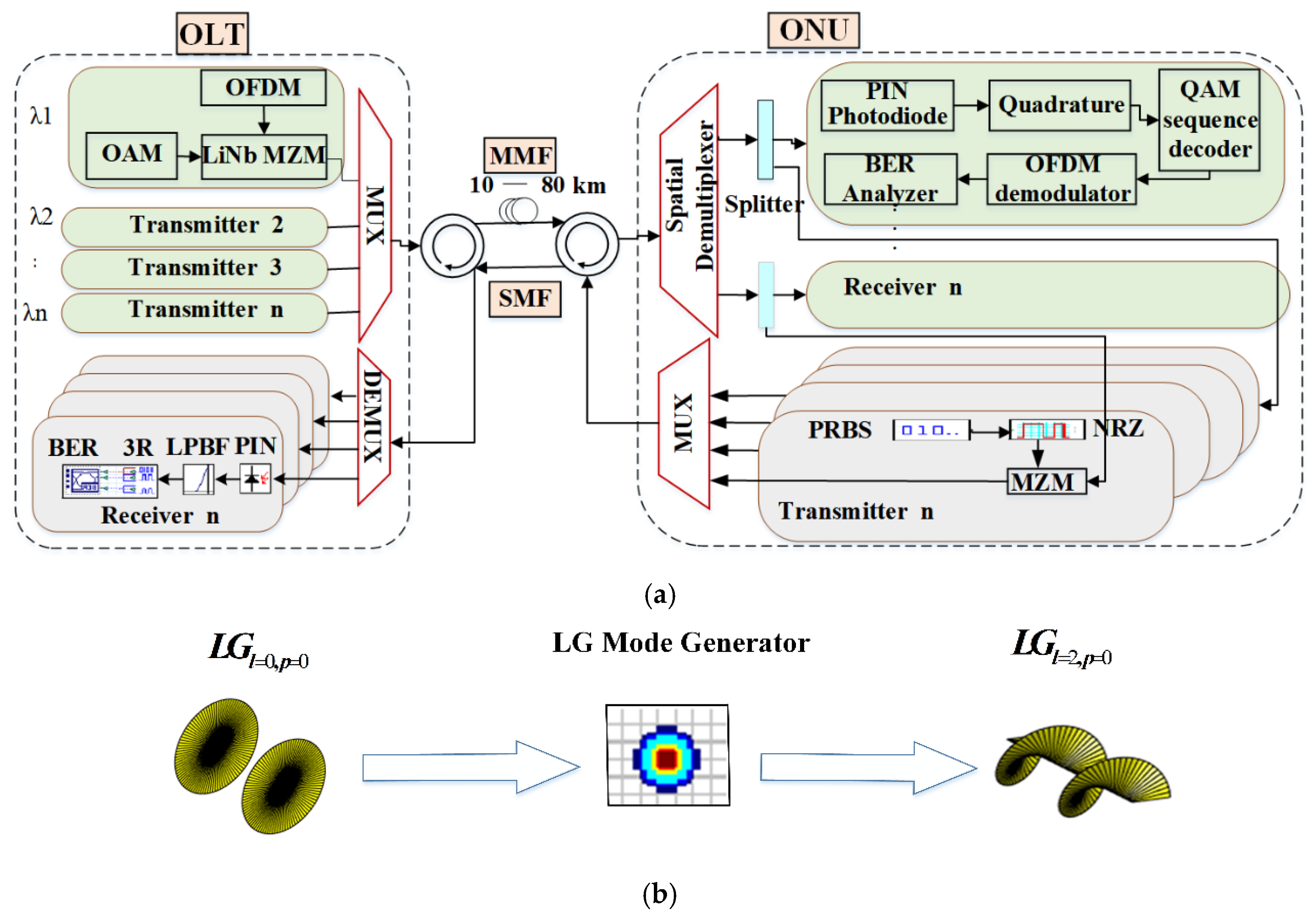
) over 10–80 km MMF is simulated using Synopis OptSim as shown in Figure 2a. Here, a classic PON with splitters and one fiber per OLT port is used in the proposed system. It consists of an optical line terminal (OLT), optical fiber link, and optical network unit (ONU). Otherwise, two OAM modes, which have a relatively large effective refractive index difference between each other, are transmitted in MMF, so mode crosstalk would suffer little mode crosstalk.
In Figure 2a, OFDM modulation is adopted in the downstream link and the OOK re-modulation technology is used in the upstream link, respectively. In addition, the spatial de-multiplexer is used at the receiver, which can de-multiplex spatial signal channel according to wavelength and then separates out all spatial modes associated with each wavelength.
There are many ways to generate OAM mode, such as helical phase plate, spatial light modulator, etc. In our work, the LG mode generation method is depicted in Figure 2b. The Laguerre Transverse Mode Generator device is employed, which attaches Laguerre-Gaussian transverse mode profiles to the input Gaussian mode x and y polarizations. It’s worth noting that the X and Y indexes describe the azimuthal and radial indexes, respectively. The list of mode indexes for each polarization, as well as the spot size and the inverse of the radius of curvature for each mode are also provided. Obviously, the LG mode can be generated successfully with this device. And the transverse electric field intensity of the L G l = 0 , p = 2   and   L G l = 0 , p = 4 mode is shown in Figure 3a,b, respectively. A and B represent the optical vortex radius. Due to the optical vortex, the petal shapes are achieved at the mode center and the central ring becomes larger as the radial value p increases, while the central light intensity gradually decreases, as plotted in Figure 3. Figure 3a,b are the 3D diagram with the transverse mode of L G l = 0 , p = 2 and L G l = 0 , p = 4 signal, respectively. The X(m) and Y(m) denote x and y polarization. The colorbar is the normalized optical field intensity distribution corresponding to Figure 3c,d.
The employed MMF in the downstream link is a conventional Y b 3 + doped multimode fiber with a step-index profile. The radii and refractive index of the fiber core are 3.4   μ m and 1.45, respectively. Yb doping radius is 3.4   μ m as well. Additionally, the standard of the single-mode fiber (SMF) fiber in the upstream link is ITU-T G.652D with dispersion coefficient for 1550 nm about 16.75 ps / nm km . OOK re-modulation is used for the upstream link. Therefore, the system structure is simplified and source-free ONU is realized owing to the modulation process without a new optical source.
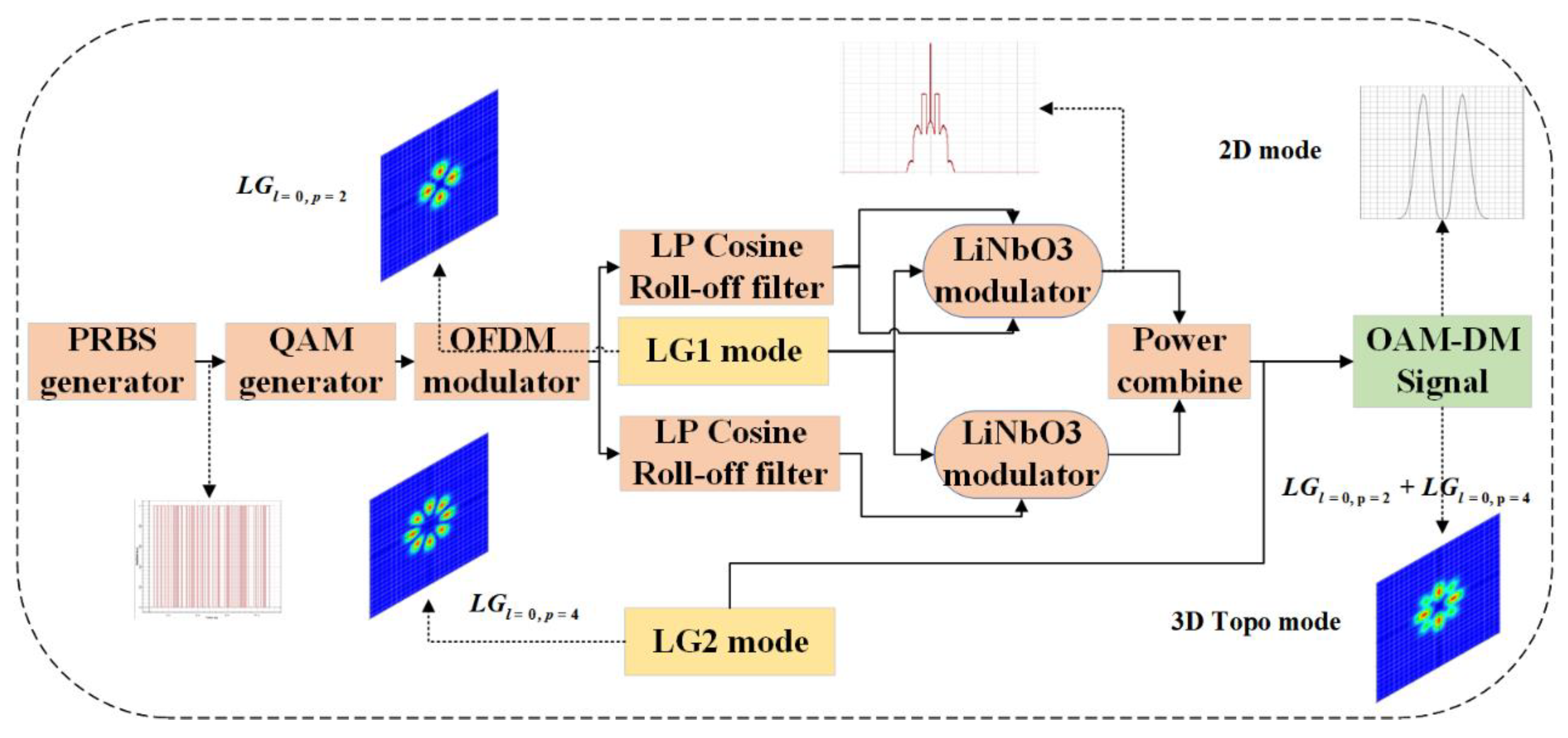
At the OLT side, two random binary sequences with a 10 Gbps data rate are provided by pseudo-random binary sequences (PRBS) generator for each wavelength and then entered into a 4-QAM generator with 2-bits per symbol sequence. Subsequently, the output 4-QAM signal is transmitted to the OFDM modulator for mapping 512 subcarriers, 1024 FFT points, and 64 cyclic prefix points. As shown in 
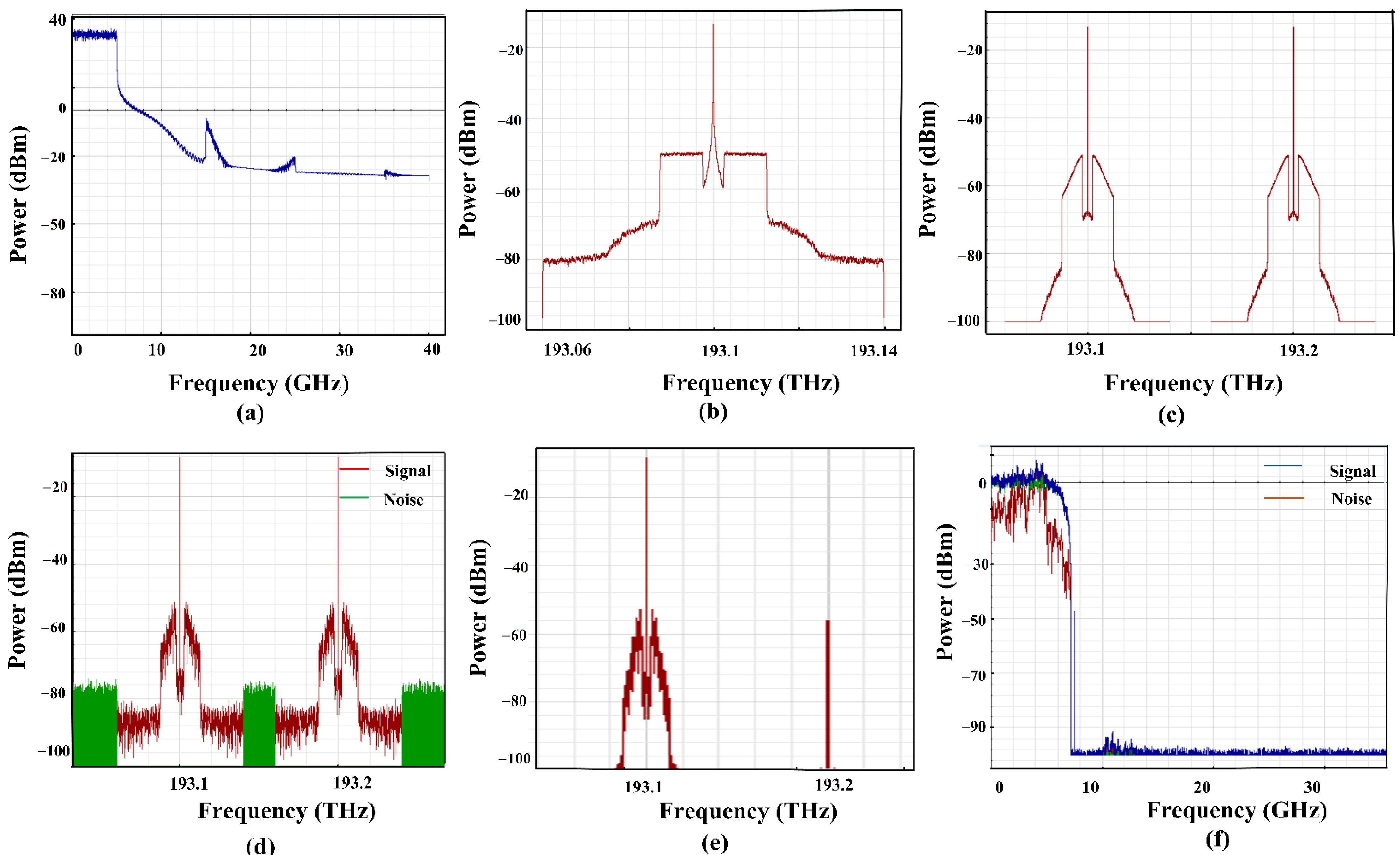
Figure 4a, the power of OFDM modulation signals is 30 dBm at both 20 GHz and 40 GHz. After the OFDM modulator, the signal gets into the quadrature modulator (QM) with a 7.5 GHz frequency through the low pass cosine roll-off filter. Both the downstream and the upstream frequencies (193.1 THz and 193.2 THz) are set with an interval of 100 GHz. These frequencies are emitted by utilizing pairs of continuous wave (CW) lasers with a linewidth of 0.01 MHz. Besides, the Gaussian mode is converted to LG mode carrying a special radial index p in a Laguerre Transverse Mode Generator. The LiNbO3 Mach-Zehnder modulator (MZM) has three input ports comprising LG mode and two electrical signals from QM. The signal spectrum at 193.1 THz after the LiNbO3 MZM is shown in Figure 4b. After that, two modulated OFDM signals based on LG mode with two wavelengths are multiplexed through a WDM multiplexer (mux) before coupling into the MMF. The multiplexed signal spectrum before and after MMF transmission is depicted in Figure 4c,d, respectively. One can be observed that the spectrum power has a remarkable decrease after MMF, which is mainly caused by the noise and attenuation effect of fiber. After propagating for a certain distance in MMF, the multiple LG-WDM signals are de-multiplexed into a single LG mode through a spatial de-multiplexer. The transmission attenuation is 0.2 dB/km. It is worth noting that the signals carried by different OAM modes cannot interfere with each other. Then, the signal is divided into two streams by a WDM de-multiplexer (de-mux) through the wavelength, as shown in Figure 4e.
At the ONU side, a fork component splits signals into two different paths, one for de-multiplexing, and one for the carrier of the upstream link. In the de-multiplexing path, the received signal via the photodetector and obtain gained by the electrical amplifier. As shown in Figure 4f, the modulated signal is de-multiplexed back to the initial signal through quadrature, OFDM demodulator, and QAM decode. For the other path, the optical carrier from the downstream link loads the non-return-to-zero (NRZ) signal through MZM for upstream transmission. In the end, the electrical signal is regenerated through the 3R regenerator and sent to the BER analyzer for bit error rate, Q-factor, and eye diagram performance measurement.
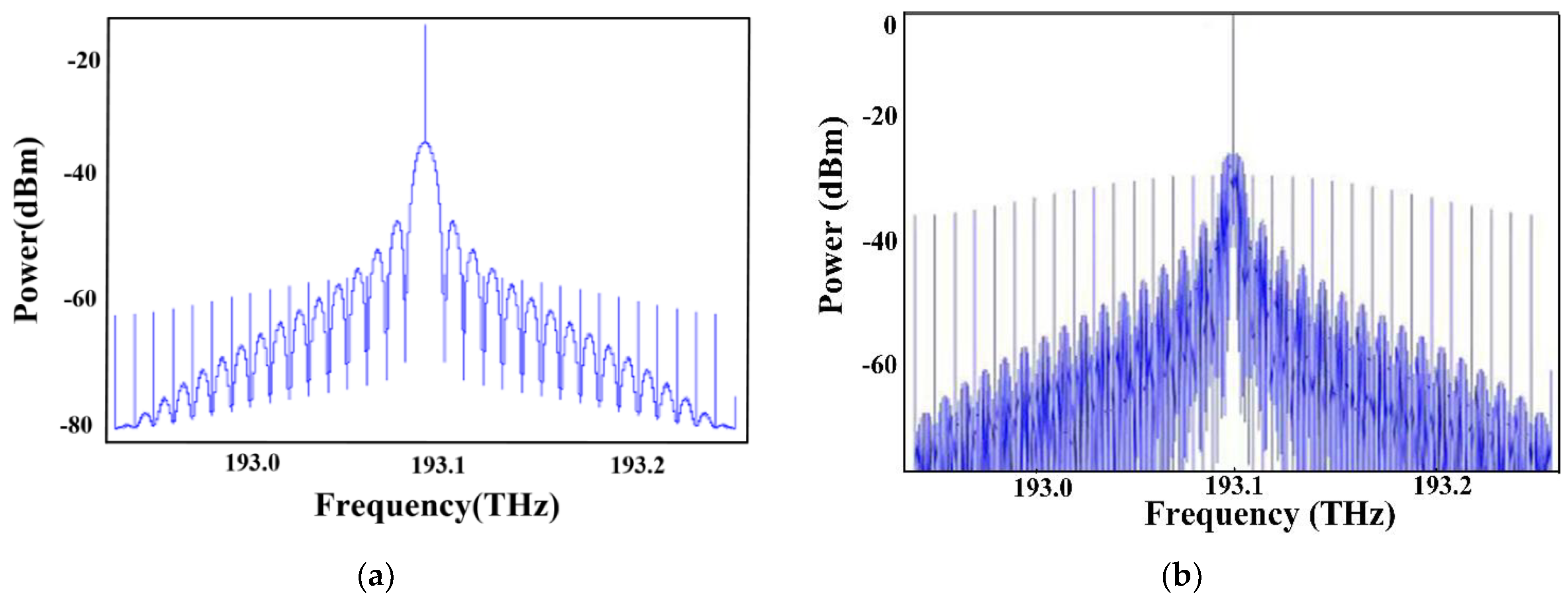
For the upstream link, each ONU using carrier re-modulation technology goes through the MZM to modulate the 20 Gbps OOK signal onto the light wave from the downstream link. It effectively saves communication costs by reducing the number of light sources. Then, the modulated signal enters into the SMF. The spectrum of upstream subcarrier re-modulation signal before and after propagating through SMF is shown in Figure 5. One can see that the power at the center frequency decreases from −10 dBm to 0 dBm after transmitting through SMF, which is mainly caused by the dispersion and propagation loss in the fiber. The receiver side consists optical amplifier, PIN photodiode, low pass Bessel filter, and 3R regenerator, as well.

4. Results and Discussion

In this section, the performance of the proposed OAM-DM-WDM-OFDM-PON system is characterized. Especially, some key parameters adopted in this study are listed in Table 1. Under the same parameter conditions, the system with QPSK and OOK modulation formats is also investigated. In the meantime, the electrical constellation diagram, eye diagram, Q factor, and BER are measured.
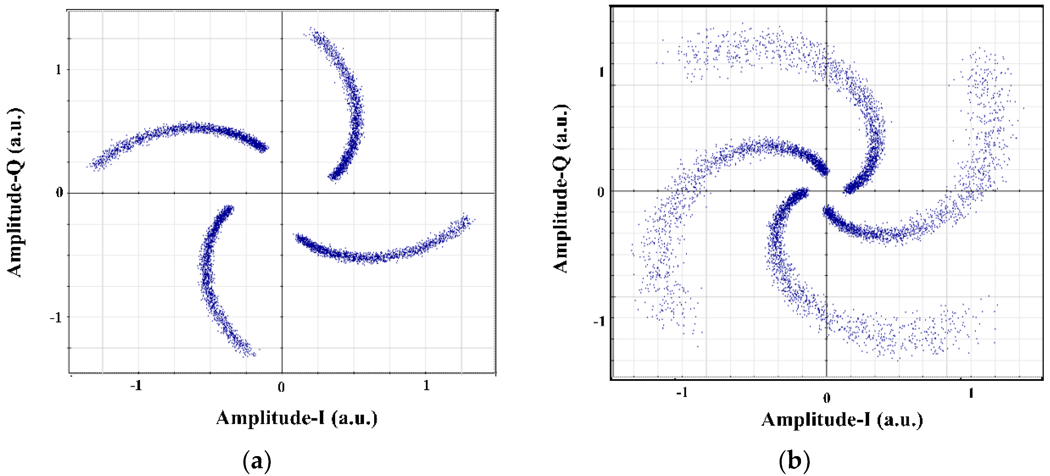
To start, the received OFDM constellation diagrams of the proposed OAM-DM-WDM-OFDM-PON system at 10 Gbps and 20 Gbps are presented in Figure 6a,b, respectively. It can be seen that the quality of the constellation diagram degrades with the data rate increases, which means the stronger attenuation introduces distortion into the signal. As shown in 
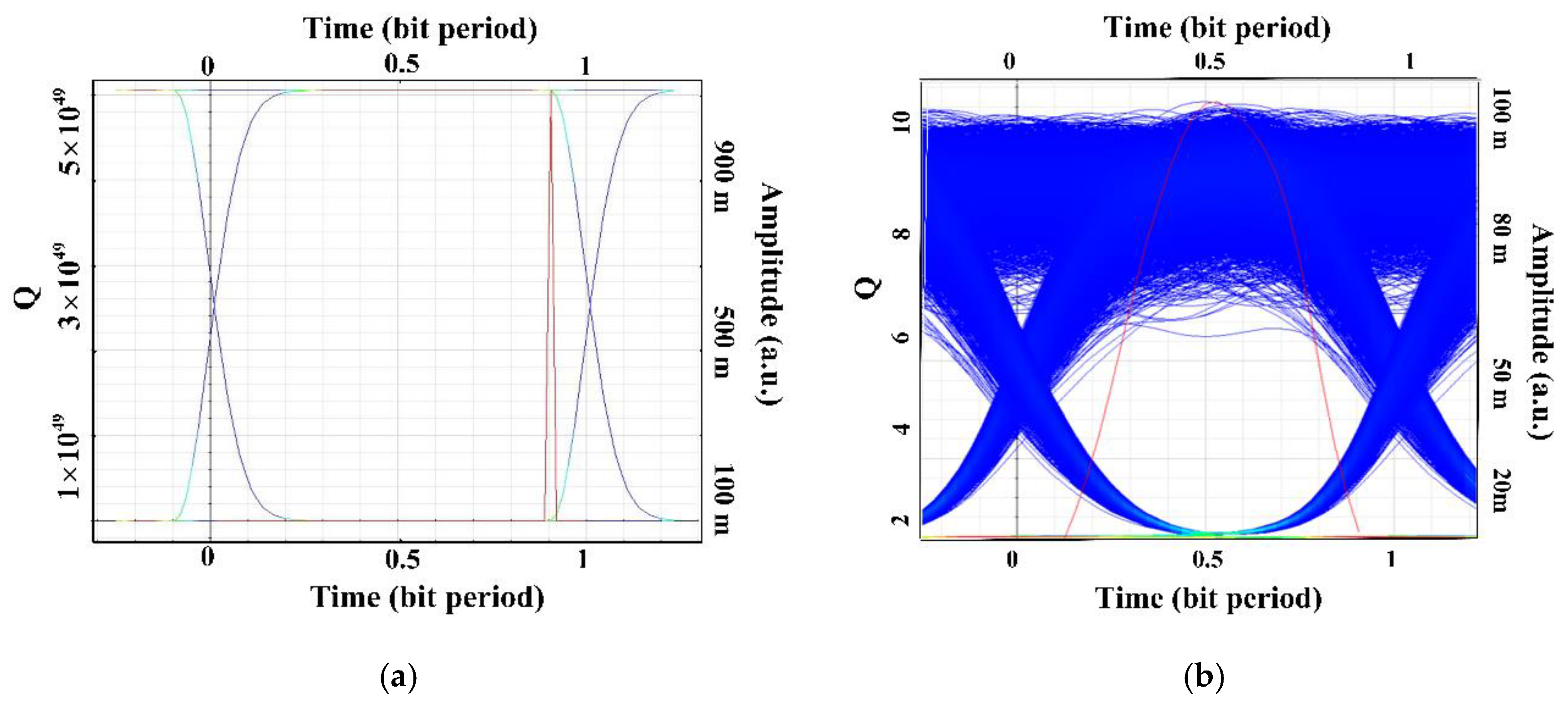
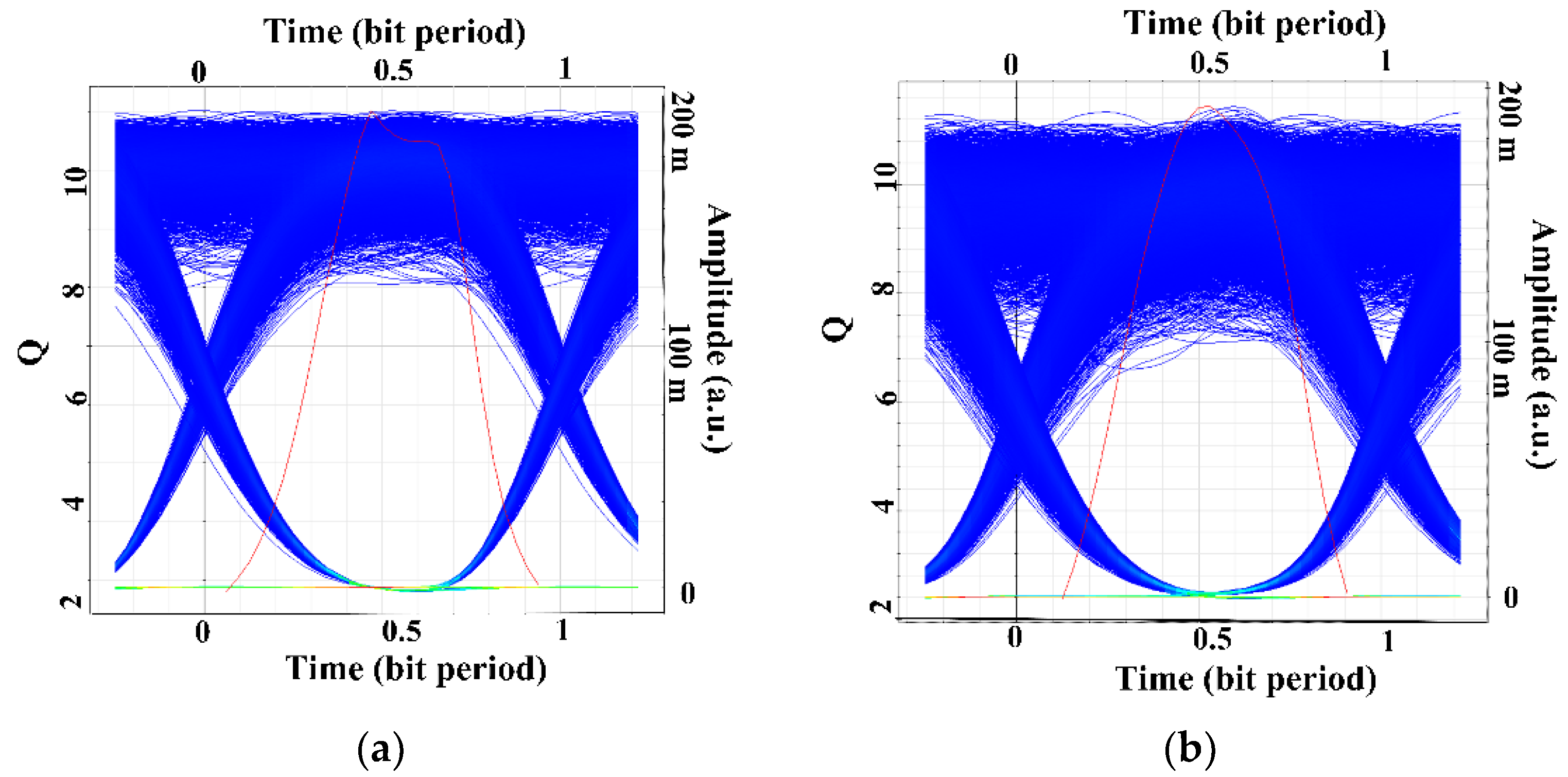
Figure 7, under 10 Gbps data rate, the eye diagrams of upstream and downstream links after 10 km propagation distance are successfully demonstrated with favorable transmission performance.
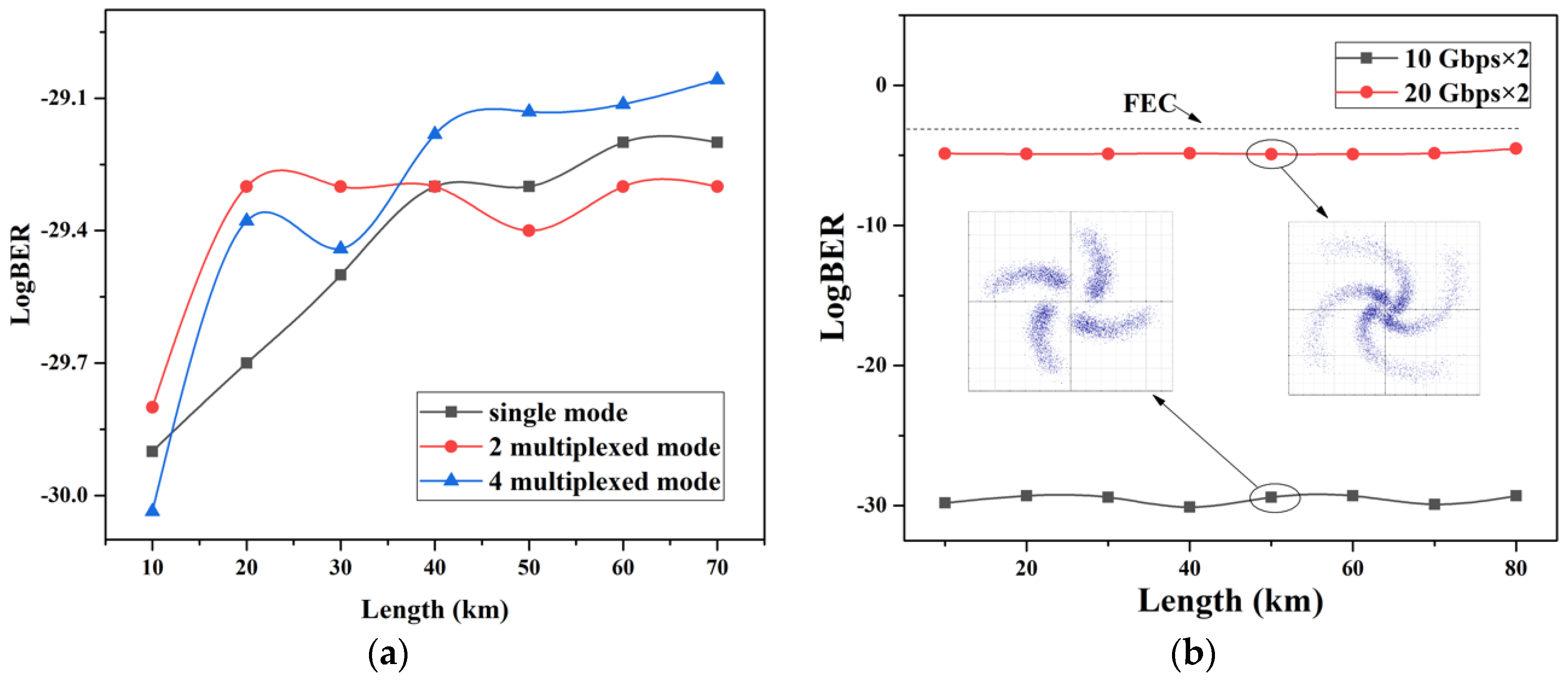
As shown in Figure 8a, the influence of OAM mode number and different transmission distances on BER is investigated in the hybrid OAM-DM-WDM-OFDM-PON system. Here, we mainly focus on the performance of the upstream link. The black dots show the BER of single OAM mode ( L G l = 0 , p = 2 ) whereas the red dots and the blue dots show the 2 multiplexed OAM mode ( L G l = 0 , p = 2   , L G l = 0 , p = 4 ) and 4 multiplexed OAM mode ( L G l = 0 , p = 2 , L G l = 0 , p = 4 , L G l = 0 , p = 6   , LG l = 0 , p = 8 ), respectively. It is observed that with the transmission distance increased, the BER performance is getting worse. The system performance of a single mode is better than multiple modes in short-distance transmission case, which is caused by mode crosstalk. Under the same BER, the 2 multiplexed OAM mode system shows significant advantages in transmission capacity thanks to its orthogonal property and low crosstalk. For the 4 multiplexed mode system, the performance deteriorates significantly over long distances owing to the mode crosstalk. With example constellation diagrams, two curves of BER under the data rate with 10 Gbps and 20 Gbps are displayed in Figure 8b. From the graph, one can find that raising the propagation rate would increase BER values. Note that all values are lower than the forward error correction (FEC) threshold of 3.8 × 10 3 . Thus, future improvements to the MMF may lead to lower crosstalk and better system performance.
Table 2 shows the BER and Q factor with CW laser power of −8 dBm, 0 dBm, and 3 dBm under 10 Gbits transmission rate, respectively. The performance of the system is degraded with the input power reduction, which is caused by the low power efficiency of each channel and thermal noise.
In addition, the main limitation to the system performance is fiber mode crosstalk. We measure the power before and after transmission through MMF, as depicted in Table 3. As a consequence, different OAM modes would suffer little mode crosstalk (<0.01 dB).
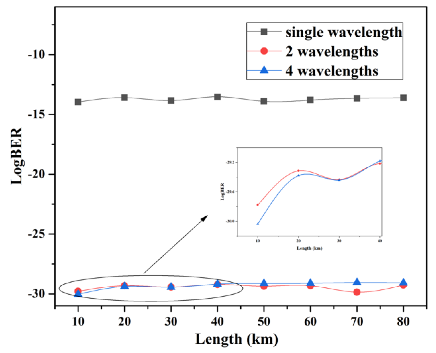
In Figure 9, simulated investigations are undertaken for the OAM-DM-PON system over a single wavelength, 2 wavelengths, and 4 wavelengths channel. For transmission distances varying from 10 km to 80 km, the BERs of the hybrid system with single and 2 wavelengths fluctuate around 10 14 and 10 30 , respectively. It can be seen that the performance of 2 wavelengths system is similar to the 4 wavelengths system. It shows that the system with 2 wavelengths as well as 4 wavelengths has a better performance compared with the single wavelength transmission. Furthermore, it can also be seen from Figure 9 that as the transmission distance increases, the BER performance of the three systems is deteriorated.
To investigate the influence of optical fiber dispersion on system performance, the eye diagrams are measured in back-to-back (B2B) transmission and 50 km fiber links, respectively. As can be seen in Figure 10, the performance of the system will decrease with the influence of the dispersion. The BER of the system under back-to-back and 50 km MMF transmission is 2.8 × 10 73 and 2.3 × 10 30 . Besides, modal dispersion also affects the power of the signal. For B2B transmission, the received power of OAM is 13.13 dBm, while the power of OAM is 27 dBm after 50 km MMF.
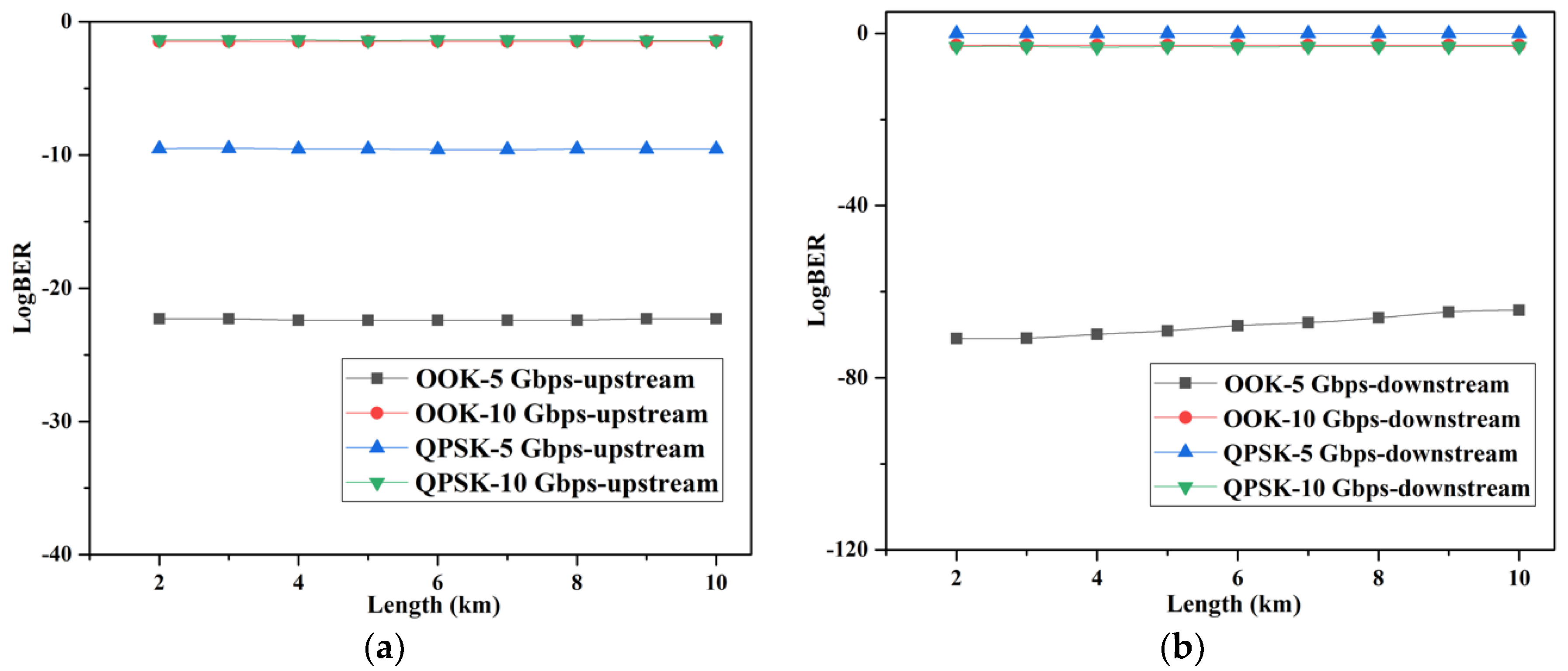
The comparative analysis of the BER features based on the OOK and QPSK modulation is plotted in Figure 11a,b. Especially, it only takes a low data rate with 5 Gbps and 10 Gbps in the system. As shown in Figure 11a, the BER values of the two systems are relatively large under 10 Gbps transmission rate. One possible reason is that the signal carriers from downstream links suffer from modal crosstalk, which reduces the optical power. Another possible reason is that the limitation of SMF leads to the attenuation of signals. Figure 11b also depicts the BER of the downstream link versus the transmission distance and a total capacity of 10/20 Gbps below the FEC limit is achieved. The results of this figure highlight the importance of modulation format and transmission rate to system performance.
From the above results, it can be concluded that the hybrid OAM-DM-WDM-OFDM-PON system based on OFDM modulation is more suitable for long-distance and large-capacity downstream transmission compared with other modulation methods.

5. Conclusions

In summary, a novel hybrid OAM-DM-WDM-OFDM-PON system is proposed, which can support two OAM ( L G l = 0 , p = 2   and   L G l = 0 , p = 4 ) modes multiplexing. With the combination of OAM-DM, WDM, and OFDM modulation, the communication capacity of the system is significantly improved. Meanwhile, the simulation results effectively prove the compatibility of OAM with WDM and OFDM techniques. Benefiting from the orthogonality of OAM modes, each LG mode over 80 km of MMF is successfully recovered at the receiver side. Besides, the measured BER of multiplexed LG mode system based on different wavelengths, as well as a single LG mode system with the same wavelength, is verified to be less than 3.8 × 10 3 in our OAM-DM-PON system. Compared with QPSK and OOK modulation, the proposed hybrid system with OFDM modulation is preferable for improving transmission capacity which can up to 40 Gbps with BER values below the FEC threshold. The simulation results demonstrate that the hybrid OAM-DM-WDM-OFDM-PON system has a strong ability to realize capacity enhancement.
The limitation of this work is that all the results are simulated. Furthermore, our research team will continue to apply it to practical environment and investigate the effects of multi-mode crosstalk on the OAM-DM-PON system to improve communication quality. In the future, the transmission capacity of optical access networks is expected to be greatly increased by introducing more OAM modes and advanced multiplexing/modulation formats.

Author Contributions

Supervision, Q.D. and X.G.; Writing—original draft, L.Z.; Writing—review & editing, H.L., J.L. (Junkai Li), X.C., Z.D., Q.Y. and J.L.(Jun Li). The authors contributed equally to this work. All authors have read and agreed to the published version of the manuscript.

Funding

This work was supported by Shandong Natural Science Foundation, China (No. ZR2017MF070); The National Natural Science Foundation for Young Scholars of China (No. 61801267); The National Natural Science Foundation of China (No. 61471224); Scientific Research Foundation of Shandong University of Science and Technology for Recruited Talents (No. skr20-1-008); Scientific Research Foundation of Shandong University of Science and Technology for Recruited Talents (No. skr-D-0104060540915); Shandong Natural Science Foundation, China (No. ZR2020MF014); Youth Fund of Natural Science Foundation of Shandong Province (No. ZR202103060092).

Institutional Review Board Statement

Not applicable.

Informed Consent Statement

Not applicable.

Data Availability Statement

Not applicable.

Acknowledgments

The authors would like to thank Yin-jing Guo for his active guidance and valuable suggestions. The authors are also grateful who have participated in this research work.

Conflicts of Interest

The authors declare no conflict of interest.

References

  1. Wang, H.Y.; Torres, F.P.; Ferrero, V.; Gaudino, R. Experimental study on 25 Gbps C-band PON over up to 25 km SMF using A 10G-class DML. Photonics 2021, 8, 328. [Google Scholar] [CrossRef]
  2. Akhtar, M.S.; Adhya, A.; Gupta, J.; Majhi, S. Cost-optimal architecture design for adaptive multi-stage TWDM-PON with PtP WDM overlay. Opt. Eng. 2021, 60, 015106. [Google Scholar] [CrossRef]
  3. Hu, Z.; Yang, Q.; Li, W.; Chan, C. Experimental demonstration of direct re-modulation for an IM/DD OFDM-WDM-PON with symmetrical bi-directional transmission. Opt. Commun. 2019, 460, 125123. [Google Scholar] [CrossRef]
  4. Wu, X.; Liu, C.; Liu, W.; Yuan, Z.; Liang, X. Monolithic integrated cyclic 64-channel AWG with MZI filters and arrayed vertical reflecting mirrors for WDM-PON application. Appl. Opt. 2019, 58, 8282. [Google Scholar] [CrossRef]
  5. Huang, C.Y.; Tsai, C.T.; Weng, J.H.; Cheng, C.H.; Lin, G.R. Temperature and noise dependence of tri-mode VCSEL carried 120-gbit/s QAM-OFDM data in back-to-back and OM5-MMF links. J. Lightwave Technol. 2020, 38, 6746–6758. [Google Scholar] [CrossRef]
  6. Bai, W.; Zou, X.; Li, P.; Pan, W.; Yan, L.; Luo, B.; Lu, X. A WDM-PON compatible wavelength-reused bidirectional in-band full-duplex radio-over-fiber system. Opt. Commun. 2020, 463, 125408. [Google Scholar] [CrossRef]
  7. Memon, A.K.; Chen, K.X. Recent advances in mode converters for a mode division multiplex transmission system. Opto-Electron. Rev. 2021, 29, 13–32. [Google Scholar]
  8. Ge, D.; Gao, Y.; Yang, Y.; Shen, L.; Li, J. A 6-lp-mode ultralow-modal-crosstalk double-ring-core FMF for weakly-coupled MDM transmission. Opt. Commun. 2019, 451, 97–103. [Google Scholar] [CrossRef]
  9. Yu, Y.; Lian, Y.D.; Hu, Q.; Xie, L.Y.; Ding, J.; Wang, Y.L.; Lu, Z.W. Design of PCF supporting 86 OAM with high mode quality and low nonlinear coefficient. Photonics 2022, 9, 266. [Google Scholar] [CrossRef]
  10. Khonina, S.N.; Porfirev, A.P.; Volotovskiy, S.G.; Ustinov, A.V.; Fomchenkov, S.A.; Pavelyev, V.S.; Schroeter, S.; Duparre, M. Generation of multiple vector optical bottle beams. Photonics 2021, 8, 218. [Google Scholar] [CrossRef]
  11. Allen, L.; Beijerbergen, M.W.; Spreeuw, R.; Woerdman, J.P. Orbital angular momentum of light and the transformation of Laguerre-Gaussian laser modes. Phys. Rev. 1992, 45, 8185–8189. [Google Scholar] [CrossRef] [PubMed]
  12. Lian, Y.D.; Qi, X.; Wang, Y.H.; Bai, Z.X.; Wang, Y.L.; Lu, Z.W. OAM beam generation in space and its applications: A review. Opt. Laser Eng. 2022, 151, 106923. [Google Scholar] [CrossRef]
  13. Zhou, J.H. OAM states generation/detection based on the multimode interference effect in a ring core fiber. Opt. Express 2015, 23, 10247–10258. [Google Scholar] [CrossRef] [PubMed]
  14. Aspden, R.S.; Morris, P.A.; He, R.Q.; Chen, Q.; Padgett, M.J. Heralded phase-contrast imaging using an orbital angular momentum phase-filter. J. Opt. 2016, 18, 055204. [Google Scholar] [CrossRef] [Green Version]
  15. Zhang, P.; Liu, B.H.; Guo, G.C. Implementation of one-dimensional quantum walks on spin-orbital abgular momentum space of photons. Phys. Rev. 2010, 81, 052322. [Google Scholar] [CrossRef] [Green Version]
  16. Liu, J.; Wang, J. Polarization-insensitive pam-4-carrying free-space orbital angular momentum (OAM) communications. Opt. Express 2016, 24, 4258. [Google Scholar] [CrossRef]
  17. Xie, G.; Ren, Y.; Yan, Y.; Huang, H.; Ahmed, N.; Li, L.; Zhao, Z.; Bao, C.; Tur, M.; Ashrafi, S. Experimental demonstration of a 200-Gbits free space optical link by multiplexing Laguerre-Gaussian beams with different radial indices. Opt. Lett. 2016, 41, 3447–3450. [Google Scholar] [CrossRef]
  18. Wang, A.; Zhu, L.; Liu, J.; Du, C.; Mo, Q.; Wang, J. Demonstration of hybrid orbital angular momentum multiplexing and time-division multiplexing passive optical network. Opt. Express 2015, 23, 29457. [Google Scholar] [CrossRef]
  19. Shi, J.; Yuan, F.; Nan, C. Time division multiplexed orbital angular momentum access system. Opt. Eng. 2016, 55, 036106. [Google Scholar] [CrossRef]
  20. Yang, M.; Wang, L.L.; Wang, H.Y.; Shen, L.; Zhang, L.; Luo, J.; Wang, J. MDM Transmission of 3-D CAP over 4.1-km Ring-Core Fiber in Passive Optical Networks. Opt. Express 2017, 25, 22991–23002. [Google Scholar]
  21. Chen, R.; Yang, W.H.; Xu, H.; Li, J.D. A 2-D FFT-Based Transceiver Architecture for OAM-OFDM Systems with UCA Antennas. IEEE Trans. Veh. Technol. 2018, 67, 5481–5485. [Google Scholar] [CrossRef]
  22. Xu, J. Generation of Laguerre–Gaussian Modes by Aperture or Array Sources. IEEE Trans. Antennas Propag. 2019, 67, 415–429. [Google Scholar] [CrossRef]
  23. Phillips, R.L.; Andrews, L.C. Spot size and divergence for Laguerre Gaussian beams of any order. Appl. Opt. 1983, 22, 643–644. [Google Scholar] [CrossRef] [PubMed]
  24. Liu, C.Q.; Ding, Q.A.; Nie, B.W.; Li, X.; Li, X.Q.; Wang, X.J.; Guo, Y.J. Design and Simulation of OFDM-PON Combined with Polarization Multiplexing and Coherent Detection. In Proceedings of the 2019 IEEE 2nd International Conference on Electronics and Communication Engineering (ICECE), Xi’an, China, 9–11 December 2019. [Google Scholar]
Figure 1. The schematic of the OAM-DM-WDM-OFDM-PON system transmitter.
Photonics 09 00448 g001
Figure 2. The schematic diagram of (a) the proposed OAM-DM-WDM-OFDM-PON system; (b) LG l = 2, p = 0 mode generation.
Photonics 09 00448 g002
Figure 3. 3-Dimension and 2-Dimension transverse electric field intensity of the (a,c) LG l = 0,p = 2; (b,d) LG l = 0,p = 4 mode. A, B: optical zero vortex radius.
Photonics 09 00448 g003
Figure 4. Spectrum diagram of (a) OFDM modulated signal, (b) signal after the LiNbO3 MZM, (c) the multiplexed signal, (d) signal after 50 km MMF, (e) the de-multiplexed signal at 193.1 THz; (f) the received OFDM signal.
Photonics 09 00448 g004
Figure 5. The upstream spectrum of the re-modulated signal (a) before; (b) after SMF transmission.
Photonics 09 00448 g005
Figure 6. Constellation diagrams of received OFDM at (a) 10 Gbps; (b) 20 Gbps data rate after 80 km transmission distance.
Photonics 09 00448 g006
Figure 7. Eye diagrams of (a) downstream; (b) upstream link after 10 km transmission distance.
Photonics 09 00448 g007
Figure 8. BER curves with (a) single OAM mode versus multiplexed OAM modes; (b) 10 Gbps versus 20 Gbps single channel data rate in the OAM-DM-WDM-OFDM-PON system upstream link.
Photonics 09 00448 g008
Figure 9. BER versus transmission distance of the hybrid OAM-DM-WDM-OFDM-PON system with different wavelengths.
Photonics 09 00448 g009
Figure 10. The upstream receiver eye diagram at (a) B2B; (b) 50 km MMF transmission distance.
Photonics 09 00448 g010
Figure 11. BER curves of the system on the OOK and QPSK modulation versus transmission distance at (a) upstream link; (b) downstream link.
Photonics 09 00448 g011
Table 1. The Main Parameters of the OAM-DM-WDM-OFDM-PON System.
ComponentParameterValueUnit
CW laserpower−8dBm
wavelength193.1, 193.2THz
linewidth0.01MHz
PRBS generatorbit rate10, 20Gbits
LG mode generatorpower ratio array1-
pox. m. n index0.2, 0.4-
QAM sequence generatorbits per symbol2bits
LiNbO3 MZMextinction30dB
OFDM de/modulatornumber of subcarriers512-
number of FFT points1024-
number of cyclic prefix points64-
Quadrature de/modulatorfrequency7.5GHz
MMFlength10–80km
attenuation0.2dB/km
refractive index profilestep-index-
core radius3.4μm
core refractive index1.45-
dispersion slope0.075ps/nm2/km
WDM de/muxfrequency193.1, 193.2THz
Spatial de-multiplexernumber of spatial modes1
Optical amplifiergain15dB
Global parametersequence length16,384-
sample per bit32-
Table 2. CW power versus BER and Q factor with 10 Gbit/s for OAM-DM-WDM-OFDM-PON upstream transmission.
PowerBERQ Factor
−8 dBm2.31201 × 10−3011.3421
0 dBm1.50521 × 10−3011.3798
3 dBm1.50344 × 10−3011.3824
Table 3. The signal-noise ratio (SNR) versus transmission distance before and after MMF.
Channel 1Channel 2
010 km020 km
SNR35.938069 dB35.932641 dB36.18193636.174332
Publisher’s Note: MDPI stays neutral with regard to jurisdictional claims in published maps and institutional affiliations.

