Control Scheme of Phase-Shifter for Photon Energy Scan
by
 , ,
, ,
Gyujin Kim
, 
Haeryong Yang
,
Chi Hyun Shim
,
Inhyuk Nam
,
Myung Hoon Cho
,
Hoon Heo
,
Changbum Kim
,
Chang-Ki Min
and
Heung-Sik Kang
* Pohang Accelerator Laboratory, Pohang 37673, Korea
*
Author to whom correspondence should be addressed.
Photonics 2022, 9(6), 418; https://doi.org/10.3390/photonics9060418
Submission received: 13 May 2022
/
Revised: 9 June 2022
/
Accepted: 14 June 2022
/
Published: 15 June 2022
(This article belongs to the Special Issue XUV and X-ray Free-Electron Lasers and Applications)
Abstract
:Variable gap undulator widely used in X-ray free-electron laser (XFEL) enables the photon energy scan by changing its gap. A phase-shifter should be incorporated to compensate for the phase mismatch between the electron bunches and X-ray pulses arising while those traverse the drift space between undulator segments. The uncertainties in both the undulator parameter and the drift space distance introduce an error in calculating the optimum gap distance of the phase-shifter for the different undulator K. The phase-shifter gap needs to be set where the error is within the tolerable range. The control scheme we propose can maintain full FEL intensity over the scanned photon energies.
1. Introduction
The X-ray free-electron lasers introduced a new realm of coherent, high-intensity X-ray sources with full transverse coherence [1,2,3,4,5]. One can change the photon energy of XFEL by adjusting the undulator gap or by varying the electron energy. Variable gap undulator is useful even in the latter case because undulator tapering requires the undulator gap change. Therefore, almost all XFEL facilities use variable gap undulators, including CW XFELs under construction [6,7]. For the Pohang Accelerator Laboratory X-ray Free-Electron Laser (PAL-XFEL) undulators, the European-XFEL undulator design (5 m long variable gap, out-vacuum undulator) was adopted and modified [8,9,10].
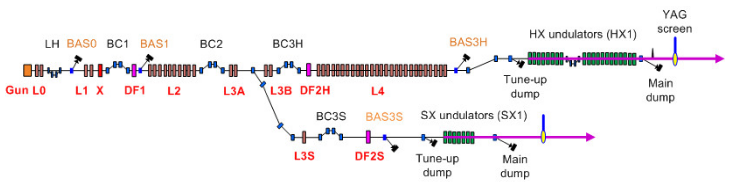
PAL-XFEL fully exploits the variable gap undulator system [11]. A hard X-ray FEL line (HX1) covers the photon energy of 2~20 keV by changing the e-beam energy (4~10.5 GeV) (see Figure 1). A soft X-ray FEL line (SX1) covers the photon energy of 0.39 to 1.25 keV by changing the undulator gap using the 3.0-GeV e-beam. The undulator K of HX1 is set to its maximum (~1.9) to get the highest gain for the 2~15 keV FEL. HX1 comprises twenty undulator segments, and SX1 consists of seven undulator segments. Nineteen and six phase-shifters are in use, respectively, for phase matching between undulator segments.
The FEL users want to change the photon energy at their convenience, freely use the photon energy scan, and incorporate it into their experiment procedure. The photon energy scan by changing the e-beam energy is pretty easy but limited in the photon energy scan range, which is typically below ±1.0% at PAL-XFEL. The larger the photon energy scan range, the more the e-beam energy change is required, making the e-beam deviate from the lattice matching condition to the undulator lattice. Therefore, if a significant photon energy change is necessary, a change in lattice matching for the new e-beam energy is needed to keep the FEL intensity at its highest.
On the other hand, the photon energy scan by changing the undulator gap (thus its K value) allows users to use a larger photon energy scan range because the e-beam is not changed. This kind of photon energy scan is performed by changing the gaps of all undulators (and thus their K values) based on the measured K value data as a function of the undulator gap. When the undulator gap changes, the free-space phase slippage occurs while the electron bunches and X-ray pulses traverse the space between undulator segments. So, there should be a phase-shifter in the drift section between two undulator segments to compensate for the phase slippage, as shown in Figure 2 [12]. A 2π phase tunability is enough for this role of the phase shifter. This undulator segment gap-based photon energy scanning should maintain full FEL intensity over the scanned photon energies.
However, the larger the photon energy scan range is, the more the phase change of the phase-shifter is required. If a range of phase integral of a phase-shifter is not enough, an abrupt change of the phase-shifter gap happens. For example, at LCLS-II, the phase shifter phase integral is much smaller than the required phase integral to do the phase-matching [13]. Therefore, the phase shifter gap changes to cover a larger range shows a number of abrupt gap change, meaning the phase shifters require gap resets to cover the entire operational range [14]. An idea of phase jumps (adding phase 2π) was introduced to overcome that problem [13,15].
For European XFEL, an appropriately large tuning range for the phase integral was chosen to avoid this discontinuity over the wavelength range: the phase number ≥14 was chosen to scan K from 1.5 to 3.9 [16,17]. The PAL-XFEL adopted the European-XFEL phase-shifter design as well [18]. This large tuning range phase shifter allows a smooth change line of the phase-shifter gap enabling a wide range scan of photon energy (see Figure 8 in ref [17]). A phase-shifter with a relatively large phase integral allows at least a total slippage of 13 times the radiation wavelength at PAL-XFEL. As a result, at PAL-XFEL, users can control the photon energy of the soft X-ray FEL line in the range of 0.39 to 1.25 keV at their convenience [19,20].
Even though this scheme with the large tuning range phase shifter is very convenient for users’ experiments, it turned out that the uncertainties in both the undulator parameter and the drift space distance introduce an error in calculating the optimum gap distance of the phase-shifter for the different undulator K. We carried out the study to figure out the contribution of two uncertainties (the undulator parameter and the drift space distance) and to seek a proper method of photon energy scan.
The method should be different for the different photon energy scan methods: the undulator segment gap-based and the electron energy-based. We propose a way to find the phase shifter’s optimum gap with a large error tolerance, considering the uncertainties in the undulator parameter Ku and the drift length between undulator segments, LD. As a result, we could successfully demonstrate the FEL output intensity stabilization during the photon energy scan.
2. Phase-Shifter to Compensate for the Slippage
Slippage (the path difference between the light and the electron) occurs due to the two contributions when the undulator gap changes: (1) slower electron speed compared to the light and (2) slowing down of the electron due to the wiggling motion. The slippage is defined as
where c is the speed of light and is the electron velocity in the moving direction. can be written as , where γ is the relativistic factor of the electron, is the deflection angle of wiggling motion due to the undulator magnetic field , where and is the undulator period.
Differentiating Equation (1) yields , and then slippage is expressed as
where the two contributions explicitly appear, and we only consider the slippage due to wiggling motion, .
The deflection angle of wiggling motion can be written as
where e is the electron charge, m is the rest mass of the electron, and . The slippage due to wiggling motion can be rewritten as
where, is so-called the phase integral. Rewriting Equation (2) yields
Introducing the phase period ,
where is the undulator deflection parameter for a planar undulator (), and using the wavelength of the generated X-ray radiation , then
The slippage along the undulator cell (LC in Figure 2) should be an integer multiple of the radiation wavelength to keep phase-matching between the light and the micro-bunched e-beam [10]:
where LC is the length of the undulator cell (6.05m for PAL-XFEL), and n is the phase number representing the phase advance in multiples of 2π [17]. and are the phase integral of the undulator and phase-shifter, respectively. Both can be calculated from the measured magnetic field. LC is a fixed variable and is an independent variable for the different K, while can be a practical control parameter easily controlled by changing the gap of the phase-shifter. The magnetic field measurement for the undulator and the phase-shifter was carried out at the field measurement lab, where the ambient temperature and earth magnetic field were controlled the same as that at the installation site in the undulator hall of PAL-XFEL [10,21]. Particularly, the ambient temperature variations should be better than ±0.1 °C to minimize the field variation of the magnetic block [21,22].
The phase slippage along the free space with a distance of LD between undulator segments is [23]
where the slippage . The free space distance of 2π phase change is defined as ). Additionally, the phase slippage along the undulator is . The phase slippage along the free space depends on the K values of the adjacent undulators, while the phase slippage along the undulator is only dependent on the constant undulator period length, λu. Therefore, when the undulator gap changes, the phase mismatch occurs while the electron bunches and X-ray pulses traverse the drift space between undulator segments.
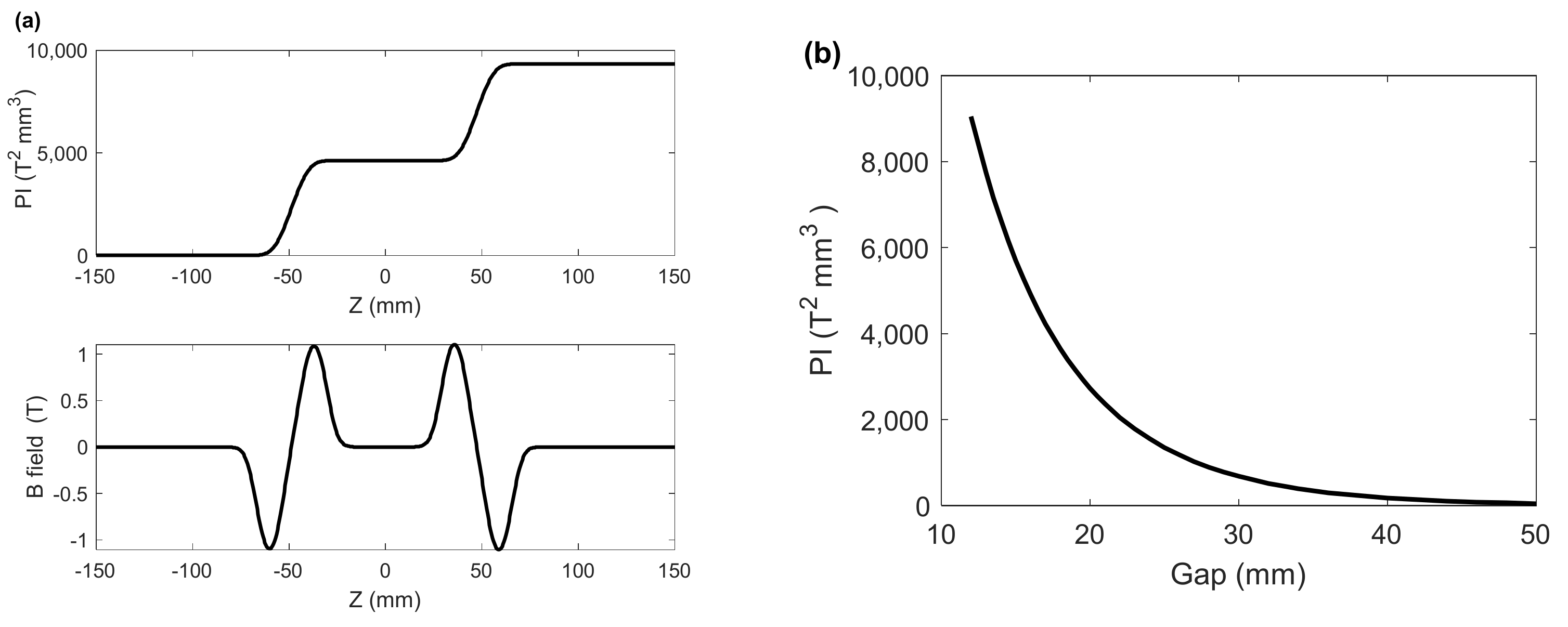
Using the undulator parameter of the soft X-ray FEL line (λu = 35 mm and Ku = 3.48), T0 = 717.5 T2·mm3 (see Table 1). The phase integral of the SX1 undulator is 8.7 × 10⁴ T2·mm3 at maximum at the gap distance of 9 mm. The required phase integral of a phase-shifter to keep a phase-matched condition is at least T0, allowing the phase number n in Equation (7). However, the maximum phase integral of the phase-shifter for PAL-XFEL was designed to have 9330 T2 mm3 [18] as shown in Figure 3, allowing at least a total slippage of . This enables a continuous change of phase shift for a wide-range scan of photon energy.
3. Finding Phase-Matching Conditions with a Phase-Shifter
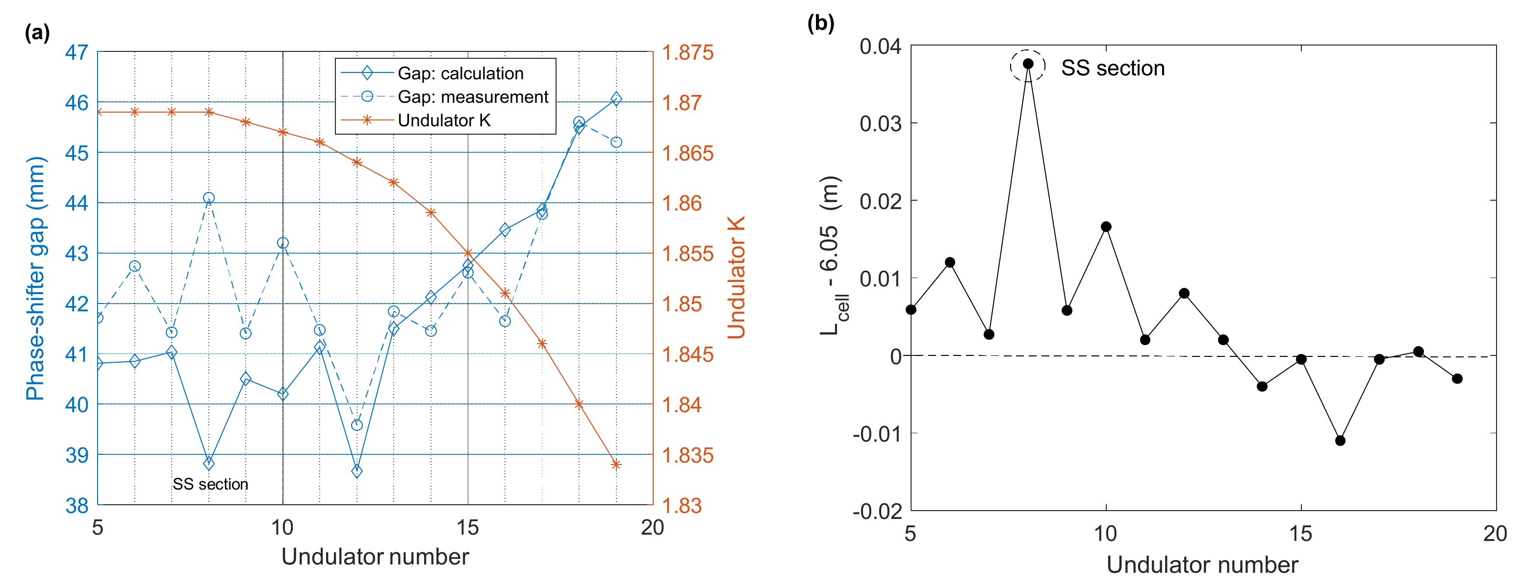
At the beginning of the hard X-ray FEL line (HX1) user service operation, we tried to set the phase shifter gap distance to the calculated value from Equation (7) for all phase-shifters. Then, we compared it with the scanning individual phase-shifter method by observing FEL intensity by a quadrant beam position monitor at the beamline. It turned out that the scanning individual phase-shifter gave rise to a better FEL intensity than the calculated. As shown in Figure 4a, there are differences in the optimum gap distances of the phase-shifters: the measurement and calculation. Our finding is that there are two uncertainties in the use of Equation (7): LD (therefore, LC) and Ku.
The uncertainties in undulator K are about the actual K the electron beam sees in the undulator. There should be a midplane offset in the undulator’s vertical direction, resulting in a slight increase in K [11]. We made the undulator mid-plane adjustment once a week for the undulators in the hard X-ray FEL line by measuring the undulator radiation measurement [11], which is absolutely necessary to compensate for the vertical motion of the undulator due to a slow ground motion. The other uncertainty in undulator K may come from an undulator tilt along the beam direction [11]. Additionally, another uncertainty in undulator K may come from the magnetic field measurement error at the field measurement lab. Those uncertainties in undulator K are almost impossible to clarify.
The uncertainties in LD are actually concerned with the undulator’s actual length, which is 5 m in design, and the undulator’s position error in the undulator cell. The phase advance in the entrance and exit region differs significantly from segment to segment [17], meaning there should be uncertainty in the undulator location and, therefore, LD. Additionally, the alignment tolerance of the undulator in the beam direction was not as strict as for quadrupole magnets.
The difference in the optimum gap distance of the phase-shifter is most significant in the self-seeding section where one undulator and a four-dipole chicane are placed, which is two times the length of the undulator cell (12.1 m for PAL-XFEL). We calculated the undulator cell distance, LC, in Equation (7), making the calculated gap distance the same as the measured assumed with no error in Ku, shown in Figure 4b. The difference from the design value (6.05 m) is not negligible. In the self-seeding section, the undulator cell distance is 12.1 m, but the corrected one increases by 37 mm. Using the hard X-ray FEL line undulator parameters (λu = 26 mm and Ku = 1.87), the free space distance of 2π phase change, , is only 71 mm. The phase tolerance of 5 degrees, for example, gives a longitudinal position tolerance of 1 mm for the undulator.
Finding out the uncertainties mentioned above, we decided to use the scanning method to find the optimum gap position of the phase-shifter for increasing FEL intensity at the hard X-ray FEL line. Another reason to use the scanning method is that we change the e-beam energy for the different photon energy in the hard X-ray FEL line with the undulator K fixed at its proper value of tapering. The scanning starts from the beginning of the undulator line because undulator tapering should be set properly at the downstream undulators taking into account the electron energy decreases due to the FEL process.
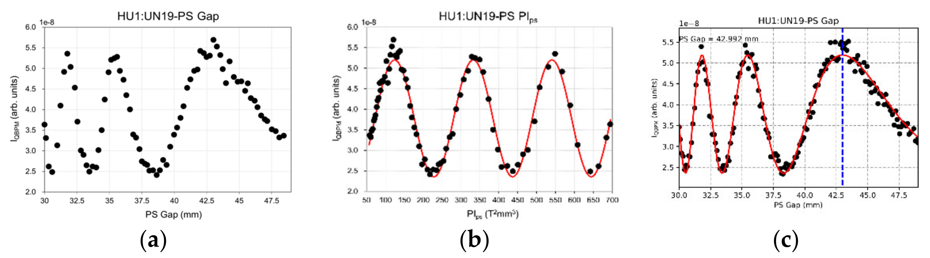
Figure 5 shows the measurement of FEL intensity as a function of the phase-shifter gap at the hard X-ray FEL line. A quadrant beam position monitor (QBPM) in the optical hutch of the beamline was used for intensity measurement [24,25]. The range of phase integral for the measurement was about 700 T2·mm3. Redrawing by changing the phase-shifter gap to phase integral (PI) clearly shows a periodically oscillating pattern (Figure 5b). Using the hard X-ray FEL line undulator parameters (λu = 26 mm and Ku = 1.87) and the phase period T0 = 207.4 T2·mm3, a sine curve fitting was carried out using the fitting equation:
where , and a, b, and c are the fitting constants. Then, converting PI to the gap distance results in the fitting result as a function of the phase-shifter gap (Figure 5c). The optimal gap of the phase-shifter can be set to one of the gap distances where the FEL intensity is at maximum. However, the preferred gap is a large number (the dashed blue line in Figure 5c) because the setting error of the phase-shifter is well within the tolerable range.
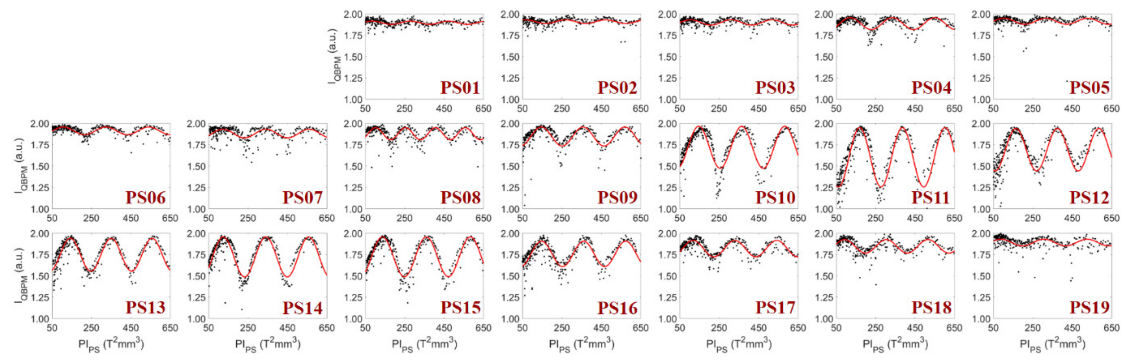
This kind of optimum gap finding for all phase-shifters helps to increase the FEL intensity in the hard X-ray FEL line. Figure 6 shows an example of the FEL intensity measurement with a QBPM as a function of and its sine curve fitting to find the gap distance for phase matching. The gap of the phase-shifter was scanned sequentially for all phase shifters starting from the beginning (PS01) to the end (PS19). In this sequential way, the optimum gap obtained through scanning is not dependent on other phase shifters. All show a periodically oscillating pattern as a function of with the same period (T0 = 207.4 T2·mm3). Additionally, the oscillation amplitude of FEL intensity as a function of increases as the undulator number increases, and reaches its peak at PS11 (after the 12th undulator). It starts to decrease from PS12, and continues to decrease as the undulator number increases further. The XFEL gets saturated around the 12th undulator among 20, and this trend resembles the behavior of the e-beam bunching factor (see Figure 7 of ref. [12]).
4. Phase-Shifter Gap Control for a Photon Energy Scan
We change the undulator gap for the photon energy scan at the soft X-ray FEL line. The photon energy is adjustable from 0.39 to 1.25 keV by changing the undulator gap (K = 1.38~3.24) using the 3-GeV electron beam. The 0.25~0.39 keV photon energy is also available by changing the gap (K = 2.58~3.4) with a reduced beam energy of 2.5 GeV.
When all undulators (seven at SX1) change their gaps to vary the photon energy, all phase shifters should also change their gaps simultaneously to maintain the phase-matching condition between undulators. Since the undulator K changes for the photon energy scan, the scanning individual phase-shifter method is impossible to apply. Thus, setting the phase shifter phase integrals is only possible with the calculated values from Equation (7).
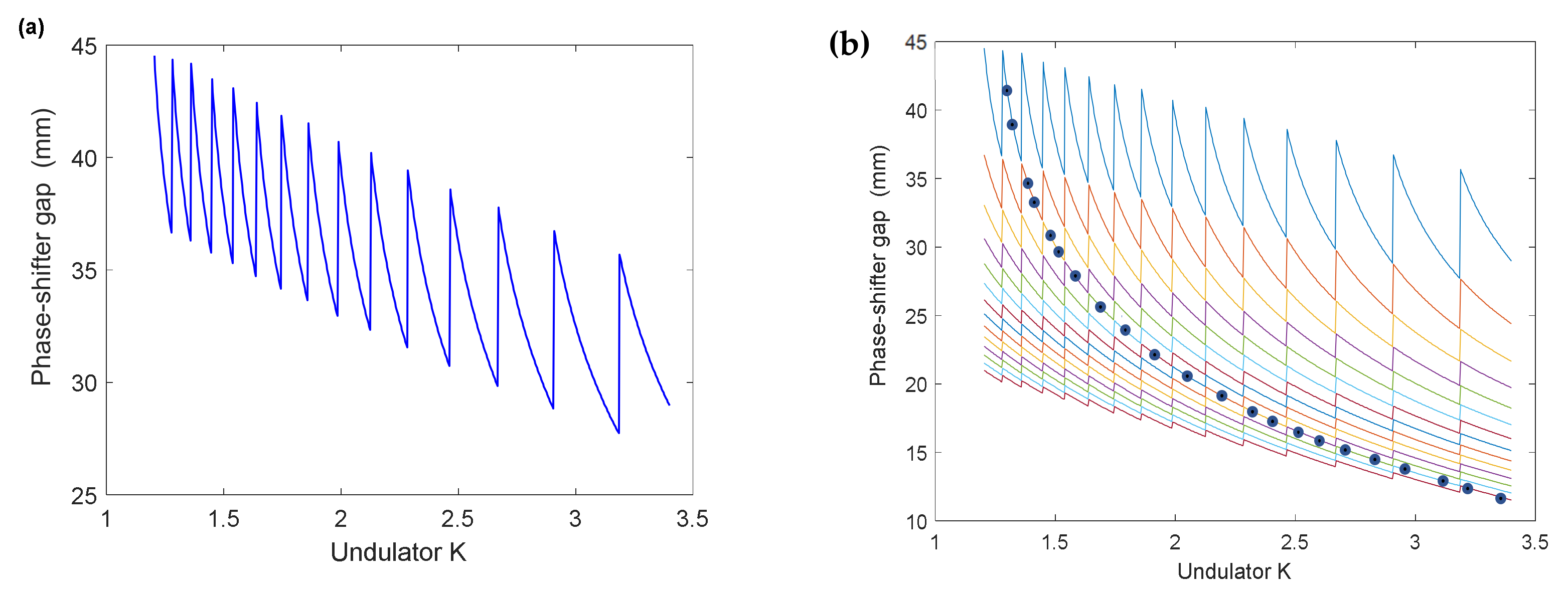
Figure 7 depicts the phase-shifter gap distance as a function of undulator K using Equation (7). The phase-shifter gap distance determined with n = 1 (Figure 7a) can be used to maintain the phase-matching condition between undulators. However, 14 cases of significant changes in gap position are shown in the figure, which may result in a drop in FEL intensity during those changes. Instead, a continuous curved line depicted in (b), consecutively connecting from n = 14 to n = 1 and marked by dots, allows us to change the gap smoothly, as explained in ref [17]. Looking at Equation (7), one can find connects consecutively as a function of K() with n changed stepwise. We chose this line as the phase-shifter gap control line for a broad photon energy control.
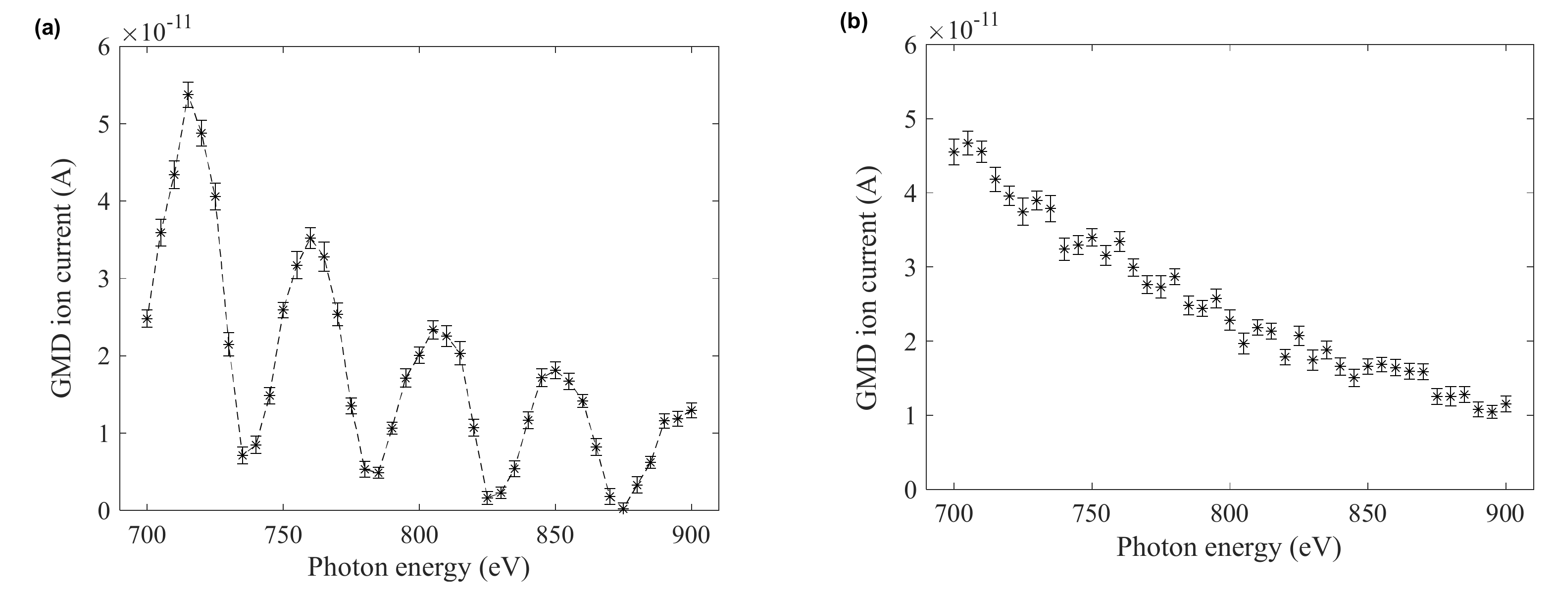
Figure 8 shows how well the phase-shifter gap control line works. In case the phase-shifter gap distance is unchanged (Figure 8a), the FEL intensity measured with a gas monitor detector (GMD) [26] shows a significant variation of the FEL intensity as the photon energy changes from 700 to 900 eV. A worst-case of a very low FEL intensity occurs at several photon energies. A sinusoidal variation of FEL intensity as a function of photon energy is clearly shown, and a phase-matching condition can be established at specific photon energies (five cases in the figure) even with the phase-shifter gap unchanged. On the other hand, if the phase-shifter gap varies according to the phase-shifter gap control line, the sinusoidal variation of FEL intensity disappears, as shown in Figure 8b. The GMD ion current shows a lower value at higher photon energy because of decreased photoionization cross-sections of gas molecules. With increasing photon energy, the photoabsorption and the photoionization cross-sections of matter generally decrease [27]. The GMD ion current decrease in Figure 8b represents only the trend of photoionization cross-sections of gas molecules. The FEL pulse energy measured by the electron energy loss scan [28] was 0.44 mJ at 700 eV and 0.4 mJ at 900 eV, meaning that the FEL intensity of Figure 8b is almost unchanged during the photon energy scan, and the phase-shifter gap control line helps keep the FEL intensity well during the photon energy scan. To keep the electron trajectory flat during the gap movement of undulators and phase-shifters, slow orbit feedback using correctors in drift space between undulators runs with a correction speed of 1 Hz for the 60-Hz beam rate. Actually, the slow orbit feedback covers the entire accelerator line from the injector end (L0 in Figure 1) to the end of the undulator line.
The peak FEL intensities at five specific photon energies in Figure 8a are higher than those with the calculated phase integrals for the phase-shifters (Figure 8b). The difference between the two is more significant at lower photon energy (~700 eV). It means that the calculated phase integrals for the phase-shifters are not optimum for phase matching, as we found in the hard X-ray FEL line. The two uncertainties (LD and Ku) may play the same role in making the calculated phase integrals from Equation (7) deviate from the optimum.
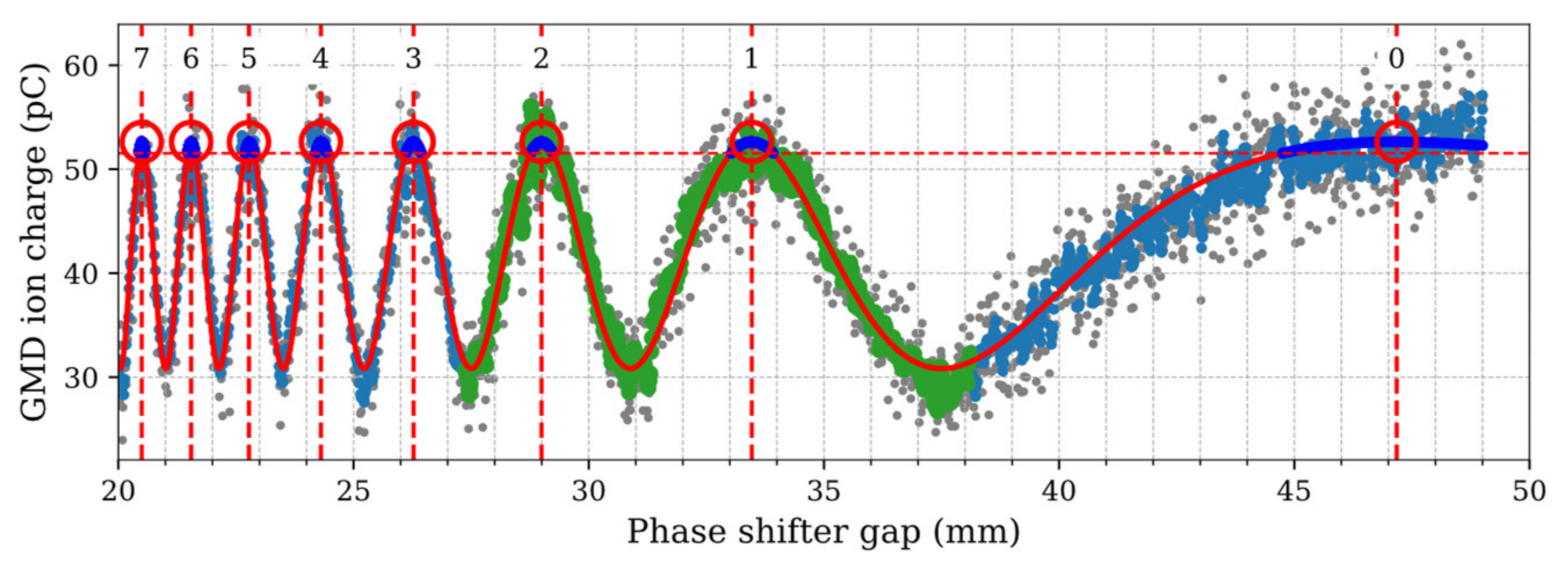
We compared the phase-shifter gap calculated from Equation (7) at five specific Ks (1.5207, 1.7411, 1.8241, 2.1140, and 2.2529) with that obtained with the scanning method to assess the effect of the two uncertainties. Figure 9 shows the measured FEL intensity (GMD ion current) as a function of the phase-shifter gap with the undulator K of 2.2529. The intensity peaks are marked with a red circle and their corresponding phase number.
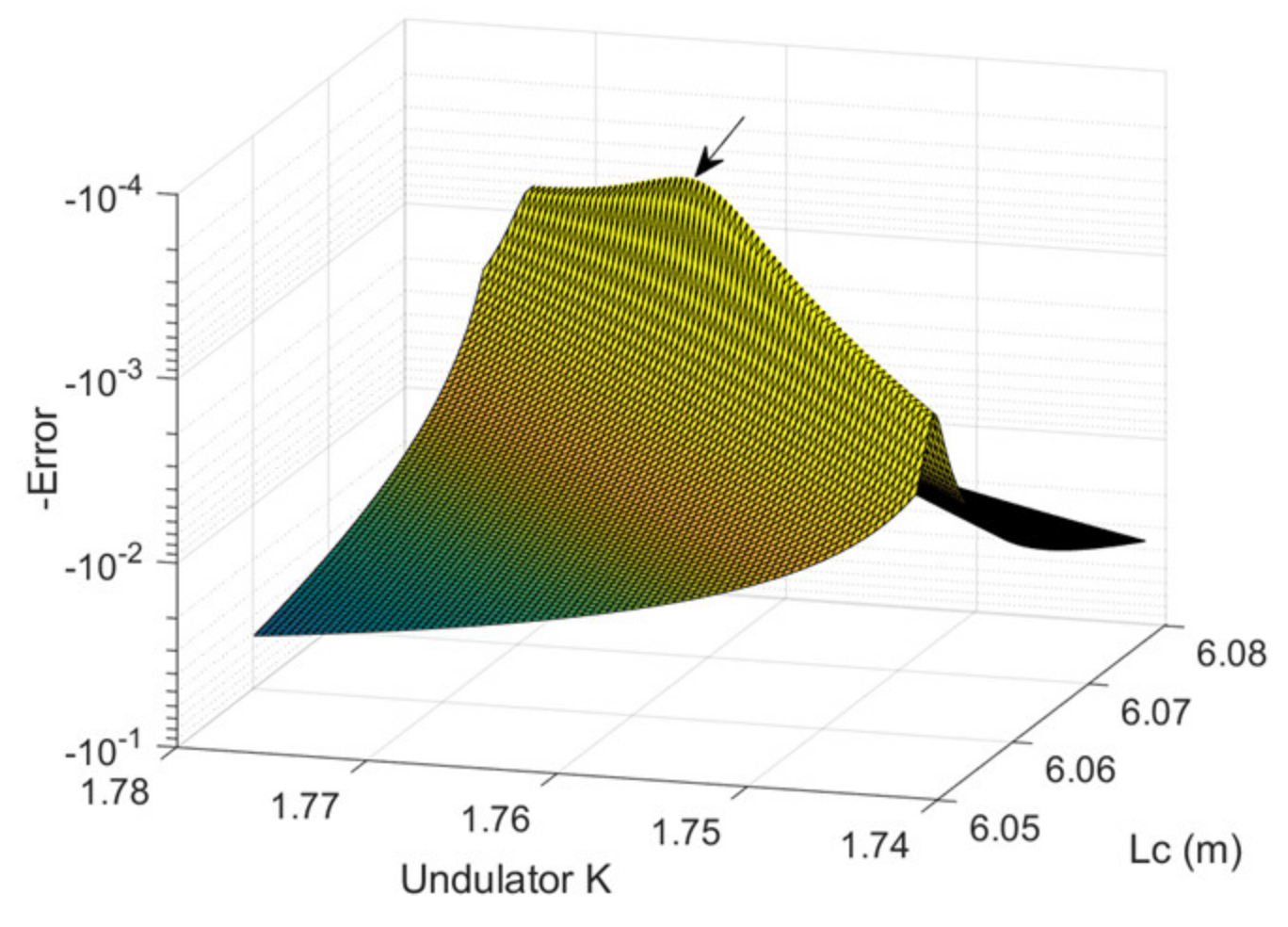
To find the exact contribution from each uncertainty (LD and Ku) for each phase-shifter, we did the minimum error search by varying both Lc and Ku. The error between the calculated gap distance (gn,cal) and the measured (gn,meas) is calculated for the different phase numbers n:
Figure 10 shows the minimum error search at K = 1.7411 for phase-shifter No. 5. The inverted surface shown in Figure 10 for the minimum search is a result of fitting to measurement data. The invert of the error is depicted to show the minimum clearly. The arrow indicates the minimum error point. The minimum error point is not predominant in the figure because of low statistics samples. Furthermore, the result at different Ks reveals an inconsistent value in Lc (Lc must be the same, independent from the undulator K). Thus, the minimum error search fails to give an exact number of Lc and Ku.
Even though we can not find the exact contribution from each uncertainty (LD and Ku), we have to use Equation (7) for the photon energy scan if we change the undulator K. There should be an error in the calculation of phase-shifter gap distance because of those uncertainties. As we see in Figure 9, the error tolerance strongly depends on where the gap of the phase-shifter is moving. The preferred one is a larger gap because the calculation error of the phase-shifter is well within the tolerable range.
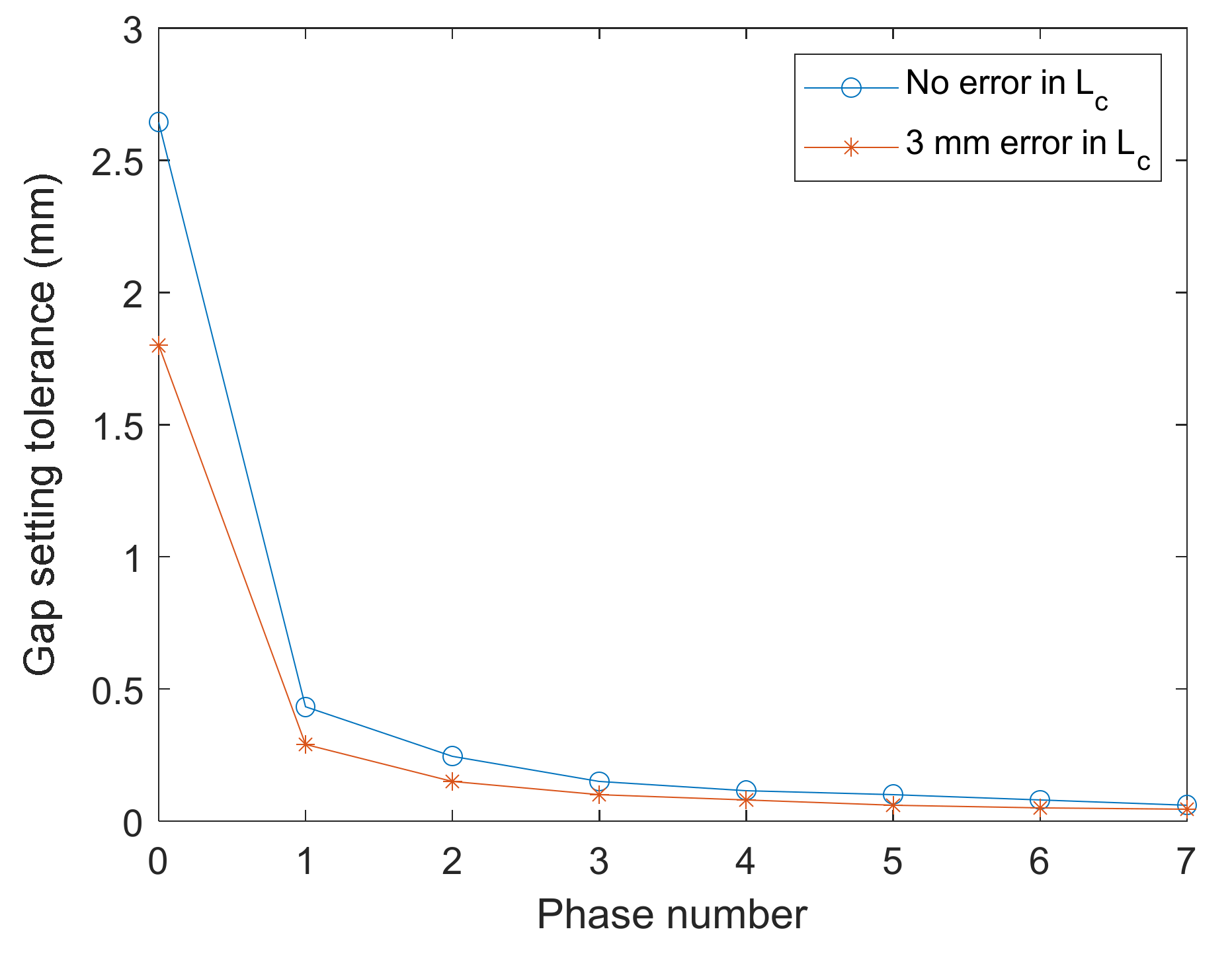
Figure 9 shows that the peak at n = 1 shows the largest tolerance of the phase-shifter gap setting while it decreases rapidly as the phase number increases. From Figure 9, the width of the phase integral for the decrease of 5% from the peak FEL intensity is 26 T2·mm3. Converting this width to the gap for n = 0 to 7 gives the gap tolerances allowing a 5% decrease in FEL intensity (see Figure 11). If an error in LC is only considered, the error of 26 T2·mm3 in the phase integral corresponds to 8.9 mm in LC. Supposing zero error in LC, the gap tolerances are 2.65 mm for n = 0, 0.43 mm for n = 1, and 0.25 mm for n = 2. If the error in LC is assumed 3 mm, the gap tolerances become worse, particularly for the phase number n > 2. Therefore, the acceptable phase number is n 2, and the phase-shifter gap distance is over 25 mm (the phase integral <1300 T2·mm3), where the FEL intensity does not vary much even with the unknown calculation error of the phase-shifter gap.
Upon acknowledging the unknown calculation error of the phase-shifter gap from Equation (7), we have to choose the appropriate phase number for the photon energy scan to let the calculation error be within the tolerance range. From Figure 11, we can conclude that the phase number should be smaller than 3 (or the phase integral is below 1300 T2·mm3). This means that we cannot use the continuous operation line shown in Figure 7b. Instead, we have to use the phase number n = 0, 1, and 2 even though it intrudes an abrupt change of the phase-shifter gap.
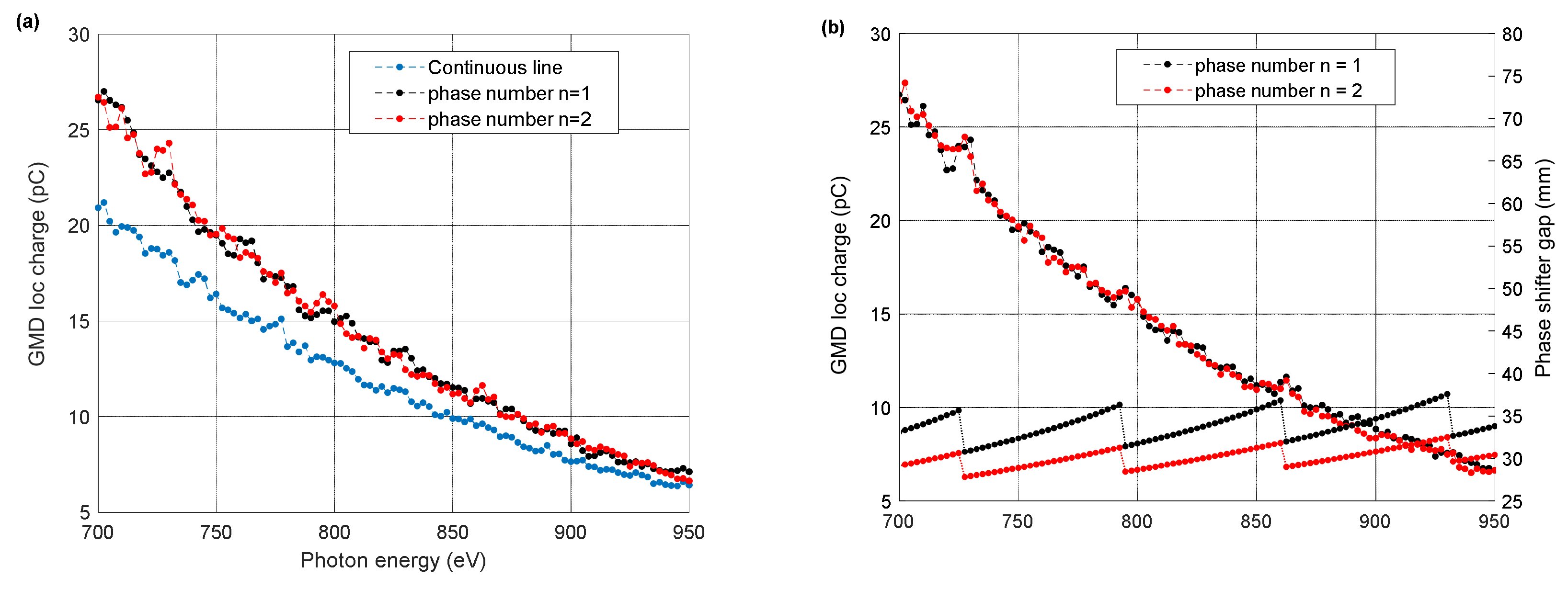
Figure 12 shows the test results of the three different cases of the photon energy scan (the scan range is 700 to 950 eV): continuous line, n = 1, and n = 2. The continuous line case exhibits the worst performance, while others show no difference in FEL intensity. In the case of n = 1 and n = 2, the FEL intensity fluctuations appear at transition points of the phase-shifter gap, as shown in Figure 12b, which looks insignificant.
5. Discussion
Properly controlling phase-matching between undulator segments is essential in maintaining full FEL intensity over the scanned photon energies for the users’ experiment. The phase-shifter compensates for slippage between the light and the electron to keep phase-matching with an integer multiple of 2π. A method is proposed to find the phase shifter’s optimum gap, taking into account the uncertainties in the undulator parameter Ku and the drift length between undulator segments, LD.
The FEL output intensity stabilization during the photon energy scan is successfully demonstrated at PAL-XFEL by appropriately tuning the gap of the phase shifters. The scanning individual phase-shifter method is adopted for the hard X-ray FEL line, where the undulator K is fixed at its proper value of tapering while the e-beam energy is adjusted for the photon energy scan. The largest tolerance of the phase-shifter gap could be found by measuring FEL intensity vs. the phase shifter gap, which can enable photon energy scan with high FEL intensities.
On the other hand, the undulator K should change for the photon energy scan at the soft X-ray FEL line. Therefore, the scanning individual phase-shifter method is impossible to apply. Instead, the calculated phase-shifter gap from the measured magnetic field data of the phase-shifter should be used for the different undulator K. The large phase integral phase-shifter was introduced to allow a continuous curved control line of the phase-shifter gap enabling a wide range scan of photon energy at the soft X-ray FEL line. However, to cover a wide range of photon energy along a single control line, the phase-shifter gap must drop below 20 mm at lower photon energy (higher undulator K), where the gap adjustment tolerance is very small.
We found that the width of the phase integral for the decrease of 5% from the peak FEL intensity is 26 T2·mm3. As the gap of the phase-shifter closes down, the magnet field amplitude goes up rapidly, and the change of phase integral per the gap change becomes steeper, as seen in Figure 3b, meaning that the error tolerance of the phase-shifter gap setting is shrinking further.
Furthermore, the calculation error of the phase-shifter gap from Equation (7) is not only nonnegligible but also unpredictable because of the two uncertainties (LD and Ku). It is found that moving to the phase number over 3 puts the error out of the tolerable range to reduce the FEL intensity appreciably. Therefore, we propose a control scheme to use the phase numbers n = 0, 1, and 2, which entails an abrupt change of the phase-shifter gap. A test with those control lines shows that the FEL intensity fluctuation is insignificant during the gap changes.
Upon acknowledging the unknown calculation error of the phase-shifter gap from Equation (7), we have to choose the appropriate phase number for the photon energy scan to let the calculation error be within the tolerance range.
Conclusively, the acceptable phase number is n 2, and the phase integral of the phase-shifter should be below 1300 T2·mm3, where the FEL intensity does not vary much with the unknown calculation error of the phase-shifter gap. Additionally, the maximum phase integral of the phase-shifter does not need to be as high as 9330 T2 mm3; it is enough with 1500 T2 mm3.
These novel procedures we propose will surely help the users of the XFEL facility to carry out successful experiments in many scientific fields.
Author Contributions
Conceptualization, C.-K.M. and H.-S.K.; methodology, C.-K.M. and G.K.; software, G.K.; validation, H.Y., C.H.S., I.N. and C.-K.M.; formal analysis, H.Y., I.N. and C.H.S.; investigation, M.H.C., C.H.S.; resources, C.-K.M. and M.H.C.; data curation, G.K. and I.N.; writing—original draft preparation, G.K., C.-K.M. and H.-S.K.; writing—review and editing, H.-S.K.; visualization, G.K. and C.H.S.; supervision, H.-S.K.; project administration, H.H., C.K. and H.-S.K.; funding acquisition, H.-S.K. All authors have read and agreed to the published version of the manuscript.
Funding
This research has been supported by the Basic Science Research Program (Grant No. NRF-2021R1A2C3010748) through the National Research Foundation of Korea (NRF) funded by the Ministry of Science and ICT of Korea.
Institutional Review Board Statement
Not applicable.
Informed Consent Statement
Not applicable.
Data Availability Statement
The data presented in this study are contained within the article.
Conflicts of Interest
The authors declare no conflict of interest.
References
- Emma, P.; Akre, R.; Arthur, J.; Bionta, R.; Bostedt, C.; Bozek, J.; Brachmann, A.; Bucksbaum, P.; Coffee, R.; Decker, F.-J.; et al. First lasing and operation of an ångstrom-wavelength free-electron laser. Nat. Photonics 2010, 4, 641–647. [Google Scholar] [CrossRef]
- Ishikawa, T.; Aoyagi, H.; Asaka, T.; Asano, Y.; Azumi, N.; Bizen, T.; Ego, H.; Fukami, K.; Fukui, T.; Furukawa, Y.; et al. A compact X-ray free-electron laser emitting in the sub-ångström region. Nat. Photonics 2012, 6, 540–544. [Google Scholar] [CrossRef]
- Kang, H.-S.; Min, C.-K.; Heo, H.; Kim, C.; Yang, H.; Kim, G.; Nam, I.; Baek, S.Y.; Choi, H.-J.; Mun, G.; et al. Hard X-ray free-electron laser with femtosecond-scale timing jitter. Nat. Photonics 2017, 11, 708–713. [Google Scholar] [CrossRef]
- Decking, W.; Abeghyan, S.; Abramian, P.; Abramsky, A.; Aguirre, A.; Albrecht, C.; Alou, P.; Altarelli, M.; Altmann, P.; Amyan, K.; et al. A MHz-repetition-rate hard X-ray free-electron laser driven by a superconducting linear accelerator. Nat. Photonics 2020, 14, 391–397. [Google Scholar] [CrossRef]
- Prat, E.; Abela, R.; Aiba, M.; Alarcon, A.; Alex, J.; Arbelo, Y.; Arrell, C.; Arsov, V.; Bacellar, C.; Beard, C.; et al. A compact and cost-effective hard X-ray free-electron laser driven by a high-brightness and low-energy electron beam. Nat. Photonics 2020, 14, 748–754. [Google Scholar] [CrossRef]
- Schoenlein, R.W.; Boutet, S.; Minitti, M.P.; Dunne, A. The Linac Coherent Light Source: Recent Developments and Future Plans. Appl. Sci. 2017, 7, 850. [Google Scholar] [CrossRef] [Green Version]
- Yan, J.; Deng, H. Multi-beam-energy operation for the continuous-wave X-ray free electron laser. Phys. Rev. Accel. Beams 2019, 22, 090701. [Google Scholar] [CrossRef] [Green Version]
- Englisch, U.; Li, Y.; Pflueger, J. Tuning and Testing of the Prototype Undulator for European FEL. In Proceedings of the 34th International Free Electron Laser Conference (FEL 2012), Nara, Japan, 26–31 August 2012. [Google Scholar]
- Pflüger, J.; Lu, H.; Teichmann, T. Field fine tuning by pole height adjustment for the undulator of the TTF–FEL. Nucl. Instrum. Methods Phys. Res. Sect. A Accel. Spectrometers Detect. Assoc. Equip. 1999, 429, 386–391. [Google Scholar] [CrossRef]
- Kim, D.-E.; Jung, Y.-G.; Lee, W.-W.; Park, K.-H.; Lee, S.-B.; Oh, B.-G.; Jeong, S.-H.; Lee, H.-G.; Suh, H.-S.; Kang, H.-S.; et al. Development of PAL-XFEL undulator system. J. Korean Phys. Soc. 2017, 71, 744–751. [Google Scholar] [CrossRef]
- Kang, H.-S.; Loos, H. X-ray free electron laser tuning for variable-gap undulators. Phys. Rev. Accel. Beams 2019, 22, 060703. [Google Scholar] [CrossRef] [Green Version]
- Shim, C.H.; Yang, H.; Hong, J.; Kim, G.; Kang, H.-S.; Cho, M.H. Intensity optimization of x-ray free-electron laser by using phase shifters. Phys. Rev. Accel. Beams 2020, 23, 090702. [Google Scholar] [CrossRef]
- Wolf, Z. Setting the LCLS-II Phase Shifters, LCLS-TN-17-3. LCLS Technical Notes. Available online: www-ssrl.slac.stanford.edu/lcls/lcls_tech_notes.html (accessed on 1 May 2022).
- Nuhna, H.-D. LCLS-II SXR Undulator Line Photon Energy Scanning, LCLS-TN-18-4. LCLS Technical Notes. Available online: www-ssrl.slac.stanford.edu/lcls/lcls_tech_notes.html (accessed on 1 May 2022).
- Wolf, Z.; Levashov, Y.; Nuhna, H.-D. Initial Test of Phase Matching an LCLS-II Undulator, LCLS-TN-18-1. LCLS Technical Notes. Available online: www-ssrl.slac.stanford.edu/lcls/lcls_tech_notes.html (accessed on 1 May 2022).
- Lu, H.; Li, Y.; Pflueger, J. The permanent magnet phase shifter for the European X-ray free electron laser. Nucl. Instrum. Methods Phys. Res. Sect. A Accel. Spectrom. Detect. Assoc. Equip. 2009, 605, 399–408. [Google Scholar] [CrossRef]
- Li, Y.; Pflueger, J. Phase matching strategy for the undulator system in the European X-ray Free Electron Laser. Phys. Rev. Accel. Beams 2017, 20, 020702. [Google Scholar] [CrossRef]
- Lee, H.G.; Kim, D.E.; Lee, W.W.; Park, K.H.; Lee, S.B.; Suh, H.S.; Jung, Y.G.; Kang, H.-S. Design and fabrication of prototype phase shifter for PAL XFEL. In Proceedings of the 4th International Particle Accelerator Conference, Shanghai, China, 12–17 May 2013; JACoW: Geneva, Switzerland, 2013. [Google Scholar]
- Park, S.H.; Kim, M.; Min, C.-K.; Eom, I.; Nam, I.; Lee, H.-S.; Kang, H.-S.; Kim, H.-D.; Jang, H.Y.; Kim, S.; et al. PAL-XFEL soft X-ray scientific instruments and X-ray optics: First commissioning results. Rev. Sci. Instrum. 2018, 89, 055105. [Google Scholar] [CrossRef] [PubMed]
- Jang, H.; Kim, H.-D.; Kim, M.; Park, S.H.; Kwon, S.; Lee, J.Y.; Park, G.; Kim, S.; Hyun, H.; Hwang, S.; et al. Time-resolved resonant elastic soft x-ray scattering at Pohang Accelerator Laboratory X-ray Free Electron Laser. Rev. Sci. Instrum. 2020, 91, 083904. [Google Scholar] [CrossRef] [PubMed]
- Park, K.H.; Jung, Y.G.; Kim, D.E.; Lee, H.G.; Suh, H.S.; Han, H.S.; Lee, S.B.; Lee, M.S.; Lee, B.H.; Sung, C.W.; et al. Field measurement facility for the PAL-XFEL undulator. J. Korean Phys. Soc. 2015, 66, 317–322. [Google Scholar] [CrossRef]
- Wolf, Z.; Levashov, Y. Temperature Dependence of the LCLS-II SXR Undulators and Phase Shifters, LCLS-TN-20-1. LCLS Technical Notes. Available online: www-ssrl.slac.stanford.edu/lcls/lcls_tech_notes.html (accessed on 1 May 2022).
- Wolf, Z.; Levashov, Y. A Phase Matching Test of the LCLS-II SXR Undulators, LCLS-TN-19-5. LCLS Technical Notes. Available online: www-ssrl.slac.stanford.edu/lcls/lcls_tech_notes.html (accessed on 1 May 2022).
- Kang, H.-S.; Yang, H.; Kim, G.; Heo, H.; Nam, I.; Min, C.-K.; Kim, C.; Baek, S.Y.; Choi, H.-J.; Mun, G.; et al. FEL performance achieved at PAL-XFEL using a three-chicane bunch compression scheme. J. Synchrotron Radiat. 2019, 26, 1127–1138. [Google Scholar] [CrossRef] [PubMed]
- Park, J.; Kim, S.; Nam, K.H.; Kim, B.; Ko, I.S. Current status of the CXI beamline at the PAL-XFEL. J. Korean Phys. Soc. 2016, 69, 1089–1093. [Google Scholar] [CrossRef]
- Hwang, S.M.; Jung, H.H.; Kim, S.; Park, J.; Kim, S.; Kim, J.; Kim, S.-N.; Park, J.; Koo, T.-Y. Development of a Gas Monitor Detector for the PAL-XFEL. J. Korean Phys. Soc. 2020, 76, 874–880. [Google Scholar] [CrossRef]
- Tiedtke, K.; Feldhaus, J.; Hahn, U.; Jastrow, U.; Nunez, T.; Tschentscher, T.; Bobashev, S.V.; Sorokin, A.A.; Hastings, J.B.; Möller, S.; et al. Gas detectors for x-ray lasers. J. Appl. Phys. 2008, 103, 094511. [Google Scholar] [CrossRef] [Green Version]
- Loos, H. Operational experience at LCLS. In Proceedings of the 2011 Free Electron Laser Conference, Shanghai, China, 22–26 August 2011. [Google Scholar]
Figure 1.
Schematic diagram of PAL-XFEL. L0, L1, L2, L3A, L3B, L4, L3S: acceleration sections; BC1, BC2, BC3H, and BC3S: magnetic bunch compressor chicanes, whose dipoles are rectangles in blue; BAS0, BAS1, BAS2, BAS3H, and BAS3S: beam analysis stations; LH: laser heater; X is an X-band linearizer cavity; DF1, DF2H, and DF2S: deflector cavity.

Figure 2.
UND and PS stand for undulator and phase-shifter, respectively. LC is the length of the undulator cell. The undulator (LU) is 5 m long, and the drift section (LD) is 1.05 m long. In the drift are a beam position monitor and a quadrupole magnet, which are not shown.
Figure 2.
UND and PS stand for undulator and phase-shifter, respectively. LC is the length of the undulator cell. The undulator (LU) is 5 m long, and the drift section (LD) is 1.05 m long. In the drift are a beam position monitor and a quadrupole magnet, which are not shown.

Figure 3.
(a) Field profile of a phase-shifter at the minimum gap and (b) phase integral as a function of the phase-shifter gap distance.
Figure 3.
(a) Field profile of a phase-shifter at the minimum gap and (b) phase integral as a function of the phase-shifter gap distance.

Figure 4.
(a) The measured and calculated gap distance of the phase-shifters in the hard X-ray FEL line. (b) The calculated undulator cell distance, Lc, to make the calculated phase-shifter gap the same as the measured.
Figure 4.
(a) The measured and calculated gap distance of the phase-shifters in the hard X-ray FEL line. (b) The calculated undulator cell distance, Lc, to make the calculated phase-shifter gap the same as the measured.

Figure 5.
(a) Measured data of FEL intensity as a function of the phase-shifter gap, (b) convert the abscissa to , a sine curve fitting, and (c) convert the abscissa data to the gap distance and apply the fitting result. In (c), the dashed blue line represents one of the optimum phase-matching conditions.

Figure 6.
Measured FEL intensity with the QBPM and its sine curve fitting (red line) as a function of the phase integral for all phase shifters from PS01 to PS19. PS01 is located between Und01 (the first undulator in the hard X-ray FEL line) and Und02.
Figure 6.
Measured FEL intensity with the QBPM and its sine curve fitting (red line) as a function of the phase integral for all phase shifters from PS01 to PS19. PS01 is located between Und01 (the first undulator in the hard X-ray FEL line) and Und02.

Figure 7.
Phase-shifter gap distance as a function of undulator K found with (a) n = 1 and (b) n = 1 to 14 at Equation (7). A continuous line is found in (b), consecutively connecting from n = 1 to n = 14, marked by dots.
Figure 7.
Phase-shifter gap distance as a function of undulator K found with (a) n = 1 and (b) n = 1 to 14 at Equation (7). A continuous line is found in (b), consecutively connecting from n = 1 to n = 14, marked by dots.

Figure 8.
FEL intensity measured with a GMD (a) with the phase-shifter gap unchanged and (b) with the phase shifter gap varied according to the phase-shifter gap control line of Figure 7b. The GMD ion current shows a lower value at higher photon energy because of decreased photoionization cross-sections of gas molecules.

Figure 9.
The measured FEL intensity (GMD ion current) as a function of the gap of the phase-shifter No. 6 at the soft X-ray FEL line. The undulator K is 2.2529. The solid red line represents the fitting of the data. The intensity peaks are marked with a red circle and their corresponding phase number. The thick bule line at peaks represents the span of the ±5% decrease in the peak FEL intensity.

Figure 10.
The minimum error search by varying Lc and Ku at K = 1.7411 for the phase-shifter No. 5. The invert of the error is depicted to show the minimum clearly. The arrow indicates the minimum error point (K = 1.7581 and Lc = 6.0671 m).
Figure 10.
The minimum error search by varying Lc and Ku at K = 1.7411 for the phase-shifter No. 5. The invert of the error is depicted to show the minimum clearly. The arrow indicates the minimum error point (K = 1.7581 and Lc = 6.0671 m).

Figure 11.
The phase-shifter gap setting tolerance allowing the 5% reduction in FEL intensity as a function of phase number.
Figure 11.
The phase-shifter gap setting tolerance allowing the 5% reduction in FEL intensity as a function of phase number.

Figure 12.
(a) The FEL intensity measured with a GMD as a function of photon energy for the three cases of photon energy scan. (b) the phase-shifter gap as a function of photon energy for the case of n = 1 and n = 2. The continuous line is the same as in Figure 7b.
Figure 12.
(a) The FEL intensity measured with a GMD as a function of photon energy for the three cases of photon energy scan. (b) the phase-shifter gap as a function of photon energy for the case of n = 1 and n = 2. The continuous line is the same as in Figure 7b.


Table 1.
Undulator parameter.
| HX1 | SX1 | |
|---|---|---|
| Undulator period, mm | 26 | 35 |
| Undulator length, m | 5.0 | 5.0 |
| Undulator parameter (max), K | 1.94 | 3.48 |
| Undulator type | Planar | Planar |
| Number of undulators | 20 | 7 |
| Drift space between undulator segments, m | 1.05 | 1.05 |
Publisher’s Note: MDPI stays neutral with regard to jurisdictional claims in published maps and institutional affiliations. |
© 2022 by the authors. Licensee MDPI, Basel, Switzerland. This article is an open access article distributed under the terms and conditions of the Creative Commons Attribution (CC BY) license (https://creativecommons.org/licenses/by/4.0/).
Share and Cite
MDPI and ACS Style
Kim, G.; Yang, H.; Shim, C.H.; Nam, I.; Cho, M.H.; Heo, H.; Kim, C.; Min, C.-K.; Kang, H.-S. Control Scheme of Phase-Shifter for Photon Energy Scan. Photonics 2022, 9, 418. https://doi.org/10.3390/photonics9060418
AMA Style
Kim G, Yang H, Shim CH, Nam I, Cho MH, Heo H, Kim C, Min C-K, Kang H-S. Control Scheme of Phase-Shifter for Photon Energy Scan. Photonics. 2022; 9(6):418. https://doi.org/10.3390/photonics9060418
Chicago/Turabian StyleKim, Gyujin, Haeryong Yang, Chi Hyun Shim, Inhyuk Nam, Myung Hoon Cho, Hoon Heo, Changbum Kim, Chang-Ki Min, and Heung-Sik Kang. 2022. "Control Scheme of Phase-Shifter for Photon Energy Scan" Photonics 9, no. 6: 418. https://doi.org/10.3390/photonics9060418
Note that from the first issue of 2016, this journal uses article numbers instead of page numbers. See further details here.