Dual Polarization Simultaneous Optical Intensity Modulation in Single Birefringent LiNbO3 Mach–Zehnder Optical Modulator


Department of Electrical & Electronic Engineering, Yonsei University, 50 Yonsei-ro, Seodaemun-gu, Seoul 03722, Korea
*
Author to whom correspondence should be addressed.
Photonics 2022, 9(6), 386; https://doi.org/10.3390/photonics9060386
Submission received: 26 April 2022
/
Revised: 23 May 2022
/
Accepted: 27 May 2022
/
Published: 30 May 2022
(This article belongs to the Topic Fiber Optic Communication)
Abstract
:A new method of simultaneous modulation of dual-polarization intensity based on a single LiNbO3 Mach–Zehnder modulator (MZM) is proposed. Using the birefringence of lithium niobate, the bipolar optical intensity can be modulated independently with the proposed modulation condition. In this paper, the optimized modulation conditions and the performance of the proposed method are investigated through simulations and experiments.
1. Introduction
Data traffic is increasing worldwide in the 5G era. As virtual reality (VR), augmented reality (AR), and Internet of Things (IoT) technologies are expected to become mainstream, the data capacity requirement is predicted to increase. The advent of artificial intelligence (AI) demands faster and more accurate signal processing. Transmission of a large volume of data requires the system to be simple. As the network becomes increasingly complex, the number of nodes increases, and more transmitters are required. As each transmitter should be simple in order to ensure the high stability and flexibility of the network, technologies for transmitting high data traffic with simpler structures are urgently required.
Several methods have been proposed to allow increased data traffic. Among these, the simplest method is to use a wider bandwidth. However, because of the bandwidth limitation of the transmitter, it is impossible to extend the bandwidth to infinity. Therefore, modulation methods that increase spectral efficiency have been investigated. On–off keying (OOK) is a representative modulation method because of its simple structure. However, owing to its low spectral efficiency, it cannot satisfy the demand for increasing data traffic. Therefore, M-pulse amplitude modulation (MPAM), which divides the signal amplitude into M levels, has been proposed as an alternative to OOK. However, to increase by 1 bit, MPAM requires two times more levels. Because a higher level requires more power to maintain bit error rate (BER) performance, MPAM has limited scalability. Moreover, because of channel characteristics such as dispersion and nonlinearity, it is difficult to increase M indefinitely [1]. To overcome these problems, modulation methods using light properties such as polarization, wavelength, phase, and mode have been proposed [1,2,3,4].
Modulation methods using phases have been proposed to increase data capacity [1,5,6,7,8,9]. Coherent detection is a representative detection method [6,7]. However, coherent detection inherently requires an optical phase-locked loop (OPLL) owing to the channel-induced phase noise (PN). This makes the link more complex. Instead, modulation called differential phase-shift keying (DPSK) has been researched. Because DPSK does not require an OPLL, it has a simpler structure. However, DPSK has limited performance when the channel is dynamically changed because it uses an optical delay line that meets the symbol length. Thus, the symbol rate should be changed in line with the channel.
Modulation methods that use modes have been proposed as alternatives [2,10,11]. However, these require complex structures. Moreover, the mode can be distorted as light passes through the channel, which causes inter-channel interference [11,12].
Wavelength has attracted attention for several years as an effective light resource for increasing data capacity. Multiplexing, also known as wavelength division multiplexing (WDM), is a representative method. However, because WDM can be used independently of other methods, it was not considered as a comparative method in this study [4].
Polarization is an attractive resource for data transmission. By using the orthogonality of each polarization, data transmission can be increased two-fold. Therefore, various modulation methods have been proposed [1,5,13,14]. These traditional polarization modulation methods require at least two or more modulators to modulate the signal because each modulator modulates a single polarization intensity. However, using the birefringence of commercial MZM, dual polarization intensity could be modulated simultaneously with a single modulator. In this case, however, each polarization intensity is interdependent. Therefore, dual polarization intensity can be modulated simultaneously but not independently.
In this study, a new intensity modulation scheme for dual polarization in a single LiNbO3 MZM is proposed and analyzed. Each polarization intensity could be modulated simultaneously and independently by the proposed method. The optimized power rate for each polarization and optimum symbol mapping were analyzed. The expected performance was simulated, and a proof-of-concept experiment was performed.
2. Schematics
It is well known that lithium niobate exhibits birefringence characteristics [15]. Each polarization axis of lithium niobate has a voltage efficiency difference of approximately three times that of the signal modulation [16]. The proposed technique uses this characteristic to apply different amplitude modulations to both polarization axes. First, an ideal MZM transfer curve was assumed. In this case, for an applied voltage V, the light component along one polarization axis (referred to as the X-axis) is modulated by the following equation:
where , refer to the amplitude of the input and output E-fields, respectively, and refers to the voltage that the MZM must apply when it modulates the intensity of the voltage-intensity transfer curve by . Assuming that the electro–light modulation efficiency of the other polarization component (Y-axis) of lithium niobate differs by exactly three times compared to the crystal axis, the light is modulated by the following equation:
The overall scheme is represented in Figure 1.
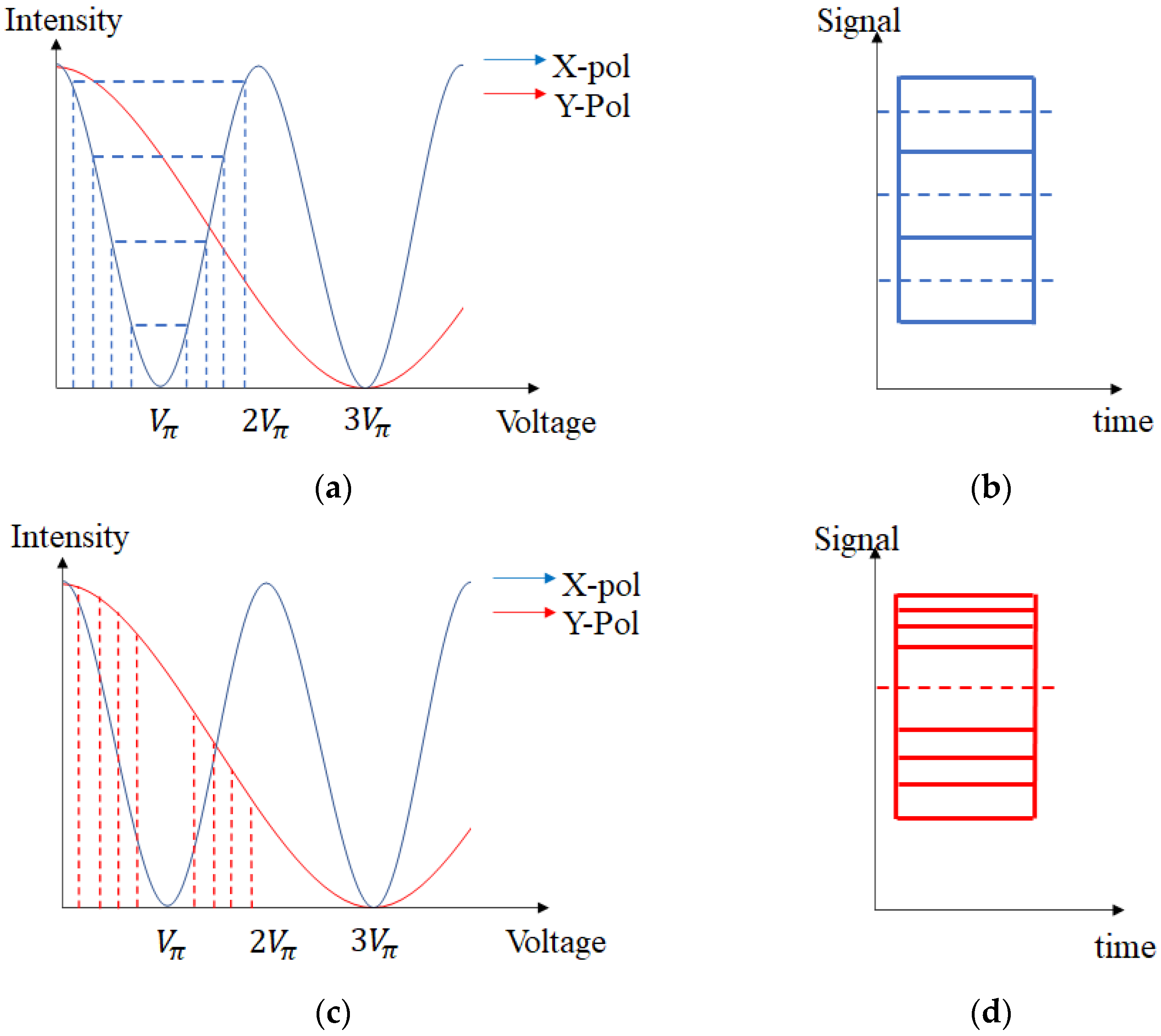
Figure 2a,c show that the transfer curve of each polarization is different. Thus, different intensity signals can be modulated for each polarization by using the same voltage signal. If the eight-voltage point is set as the input symbol voltage, as depicted in Figure 2a,c, then the intensity of each polarization is modulated differently due to the birefringence of MZM. By adequately tuning the bias and points, one axis can be modulated as PAM4, and the other axis can be modulated as OOK. Figure 2b,d depict the expected eye diagrams of each polarization. In this case, the eight-voltage point is just an example. The modulation order could also be adjusted arbitrarily. MPAM could be modulated in the X-axis, and OOK could be modulated in the Y-axis.
There are two issues associated with this method. The first is the power division. The optimal power rate for each polarization needs to be determined. The other is symbol mapping, which determines the optimal bias and voltage symbol points. These issues cannot be solved independently because both can affect the signal power of each polarization. Thus, these two issues must be optimized simultaneously.
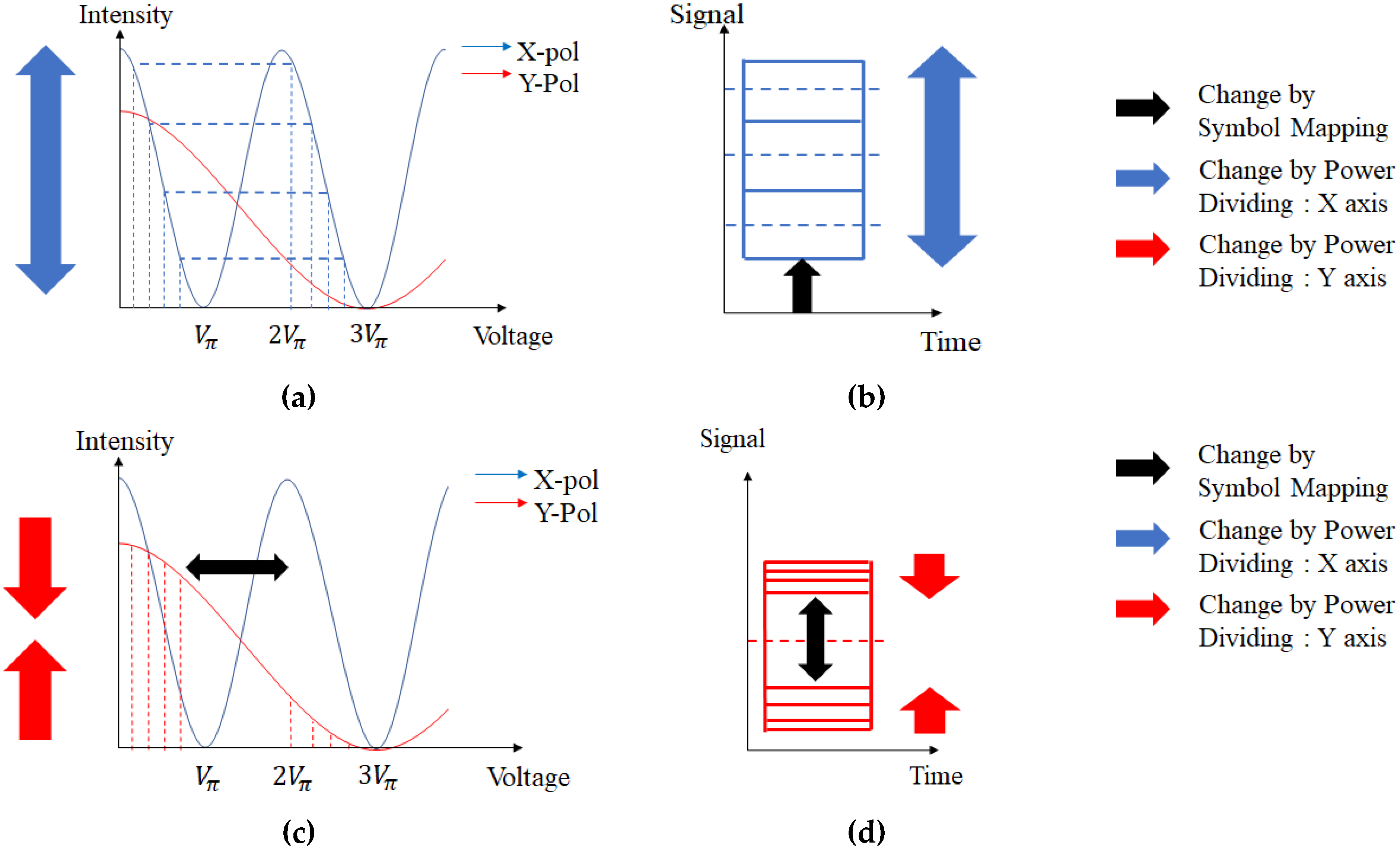
Figure 3 shows the eye diagrams and transfer curves when symbol mapping and power-dividing are changed. The blue and red arrows show the polarization rate change (power-dividing change), and the black arrow shows the symbol mapping change. As shown in Figure 3, the blue and red lines are inversely proportional to each other. This is because the total power is limited. Therefore, if the power allocated to the X-axis increases, the power allocated to the other axis decreases. The symbol mapping change, depicted as a black arrow, changes the signal power of each axis. If the eye of the Y-axis increases, the eye of the X-axis should decrease as both polarizations are modulated with a single input voltage signal. Thus, optimization of the symbol mapping change depends on the signal power.
Because one axis transmits the MPAM signal and the other transmits OOK, we assume that the total number of bits, N, is transmitted in the ratio X:Y = N-1:1. Assuming gray coding, the total BER equation is as follows:
For a typical MPAM, the SER equation is as follows [17]:
where refers to , the average symbol power–noise ratio. Here is defined as follows:
where refers to the maximum amplitude and refers to the minimum amplitude that the modulator can generate. Therefore, for a given , if and are determined, SER can also be determined. Therefore, using Equations (4) and (5), we get:
Then, if the MPAM is modulated along the X-axis and OOK is modulated along the Y-axis, Equation (3) can be modified as follows:
If is a fixed value, the BER performance is only affected by and . Each term must be normalized for optimization. From Equations (1) and (2), the intensity for each polarization is determined as follows:
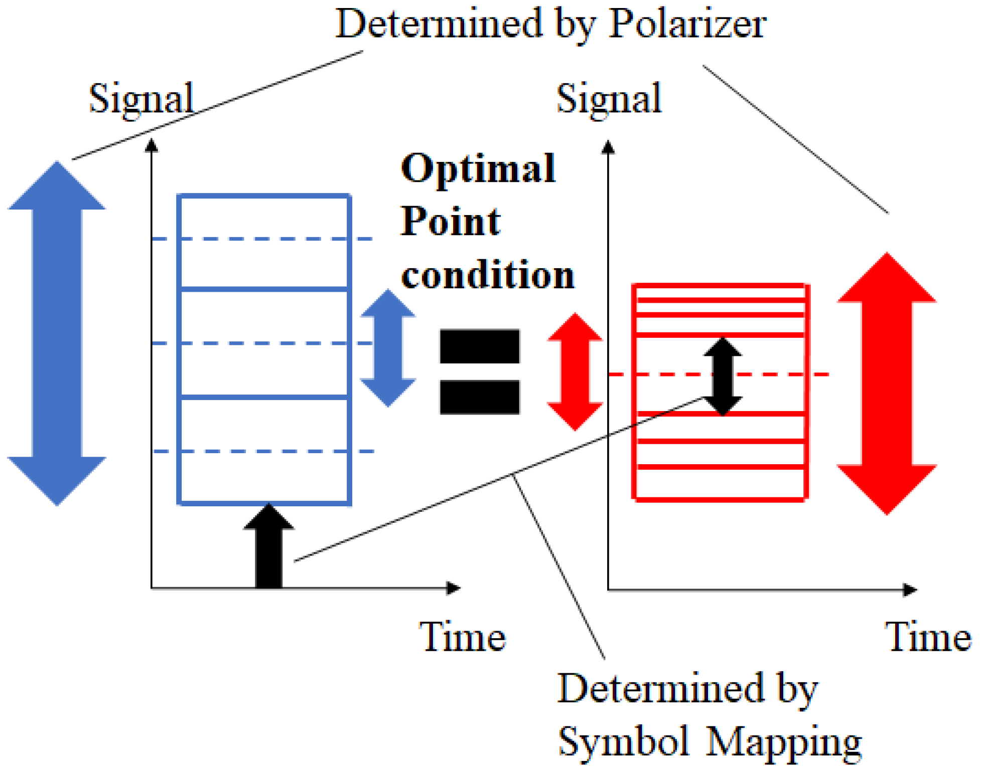
where refers to the polarization dividing ratio and refers to the intensity. Therefore, if one voltage signal (symbol mapping) and are determined, and are automatically determined by Equation (8). If the MZM has an ideal cosine curve, the optimal point is determined as shown in Figure 4.
The optimal point is the point where the eye per bit for each polarization is equal. This is because the power distance between the symbols determines the error rate. A smaller number of eyes per bit indicates that insufficient power is allocated to the polarization axis. Therefore, sufficient signal power should be allocated by adjusting the symbol mapping and polarization power division. In addition, to maximize efficiency, the symbol should be modulated in the 3 range, as depicted in Figure 3, rather than in the 2 range, as depicted in Figure 2. This is because the Y-axis distance decreases when it is modulated within the 2 range.
3. Simulation and Experimental Results
The proposed technique was simulated and experimentally demonstrated under the optimal conditions mentioned above.
3.1. Simulation
The simulation was conducted assuming that the MZM has an ideal transfer curve and that LiNbO3 has exactly three times the refractive index difference. The relative optical power vs. BER graph of the proposed technique was then compared to that of MPAM. Each graph was composed of a modulation method with the same spectral efficiency, for example, OOK–OOK and PAM4, and PAM4–OOK and PAM8. It was confirmed that the entire linear region was fully used for both the proposed technique and MPAM. In addition, it was assumed that the range was used to maximize performance. In Figure 5, the blue line represents the BER graph of MPAM, and the orange line depicts the BER graph of the proposed technique. The relative optical power is the relative power of light, assuming that the noise power is fixed. As shown, for all cases, the BER performance of the proposed technique was better than that of the MPAM technique. In addition, as the modulation order increased, the difference between the proposed technique and MPAM increased. As the total modulation order increases, the MPAM modulation order also increases along the X-axis. This makes the eye per bit smaller on the X-axis. As the simulation was conducted assuming the optimal condition in Figure 4, more power should be allocated to the X-axis to make the eye per bit of each axis equal. Accordingly, the power that should be allocated to the Y-axis decreases as the order increases. Because the power allocated in the Y-axis is 1 bit, less power is required to increase it by 1 bit as the order increases.
3.2. Experimental Results
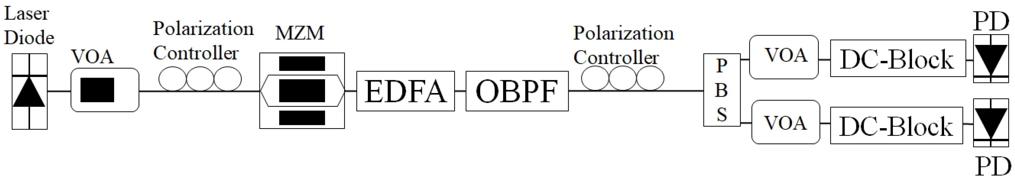
Based on the above theories, an OOK–OOK experiment in a commercial MZM was conducted as a proof-of-concept. Figure 6 shows the overall experimental scheme. However, because the MZM in the laboratory had an internal polarizer to decrease the Y-axis power for MZM performance, the experiment could not be conducted under optimal power-dividing conditions. Therefore, more power was allocated to the Y-axis and amplified by the EDFA. In addition, the RF amplifier in the laboratory had a limited range; thus the experiment could not be conducted under the optimal 3 condition depicted in Figure 3. Therefore, the experiment was conducted within range. A 2.5 Gbps experiment was conducted for each axis with a back-to-back system.
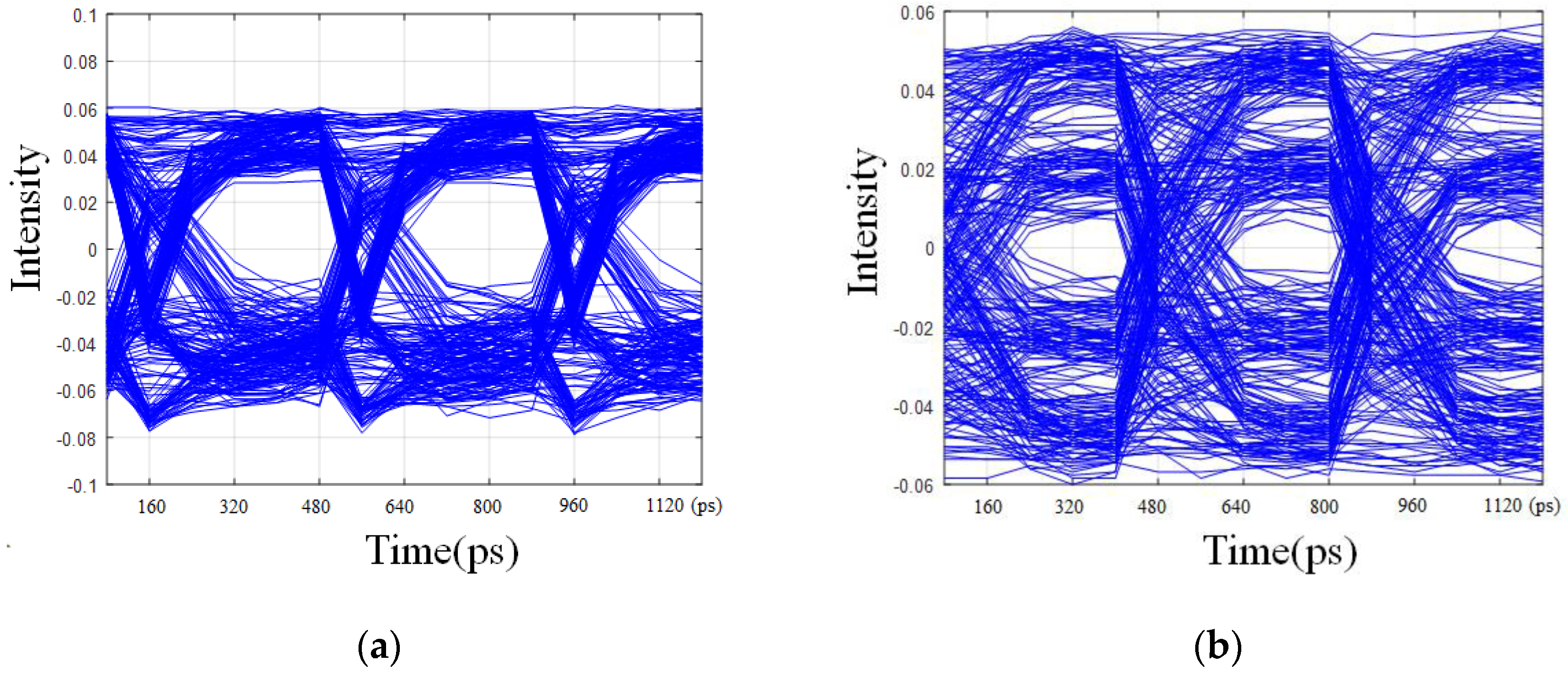
Figure 7 depicts the eye diagram for each polarization. As shown in Figure 2 and Figure 3, the X-axis has only two levels, but the Y-axis has more levels.
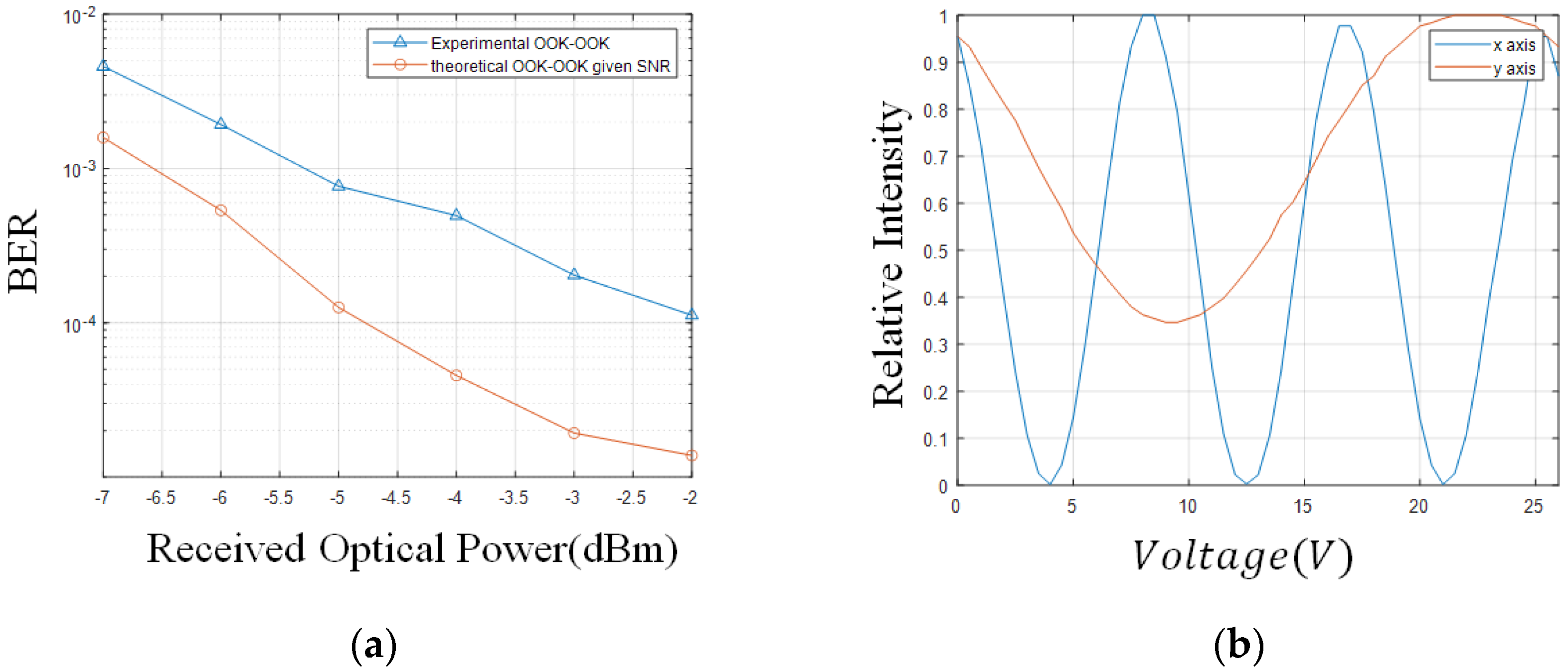
The received optical power vs. BER graph for theoretical OOK–OOK and experimentally measured OOK–OOK is depicted in Figure 8a. In this graph, the received optical power is the total received power of each axis. The theoretical value is the simulated BER when the voltage swing is in a range for the given noise power. It can be seen that the measured OOK–OOK performance is less than the theoretical value. This is because, as mentioned above, the experiment could not be conducted under optimal conditions owing to the internal polarization of the MZM in the laboratory and the limitations of the RF amplifier. The measured voltage-intensity transfer curve for each axis is shown in Figure 8b. It can be observed that the Y-axis transfer curve is not an ideal transfer curve. This limits the performance of the proposed technique. However, these were all experimental errors. If the experiment is performed under optimal conditions, modulation with a higher spectral efficiency can be conducted with a single MZM.
4. Conclusions
In summary, we proposed a new modulation method with higher spectral efficiency and a simpler structure. Unlike traditional polarization modulation methods that require two or more modulators, by using the birefringence characteristic of LiNbO3-based MZM, the intensity modulation of both polarizations could be conducted with a single MZM. The optimal condition for the proposed method plus simulation and a proof-of-concept experiment was conducted. The polarization rate and voltage swing were optimized when the symbol distance per bit for each polarization was equal. The simulation result showed that as the order increased, the spectral efficiency of the proposed method also increased. This is because as the order increases, less power is required for the Y polarization. The experiment result showed that dual polarization intensity modulation is actually possible with a -based modulator. Despite the spectral efficiency advantages, it was checked that a higher electrical voltage swing is required for this method. Further, it was confirmed that the MZM should have a high extinction-ratio Y polarization transfer curve. However, these are experimental issues. With a feasible MZM and amplifier, we expect that the proposed technique will be useful in future high-speed optical transmission requiring a simpler structure.
Author Contributions
Conceptualization: Y.-J.H.; methodology, Y.-J.H.; software, Y.-J.H.; validation, Y.-J.H. and J.-Y.C.; formal analysis, Y.-J.H.; investigation, Y.-J.H.; resources, Y.-J.H.; data curation, Y.-J.H.; writing—original draft preparation; Y.-J.H.; writing—review and editing, J.-Y.C.; visualization, Y.-J.H.; supervision, S.-K.H. All authors have read and agreed to the published version of the manuscript.
Funding
This work was supported by a grant from Institute for Information and Communications Technology Promotion (IITP), funded by the Korean government Ministry of Science and ICT (MSIT) grant no. 2019-0-00685, free-space-optical-communication-based vertical mobile network.
Institutional Review Board Statement
Not Applicable.
Informed Consent Statement
Not Applicable.
Data Availability Statement
Not applicable.
Conflicts of Interest
The authors declare no conflict of interest.
References
- Park, H.J.; Ha, I.H.; Kang, S.M.; Shin, W.H.; Han, S.K. 3D QAM-DPSK Optical Transmission Employing a Single Mach–Zehnder Modulator and Optical Direct Detection. J. Lightwave Technol. 2020, 38, 6247–6256. [Google Scholar] [CrossRef]
- Hong, Y.-Q.; Han, S.-K. Polarization-dependent SOA-based PolSK modulation for turbulence-robust FSO communication. Opt. Express 2021, 29, 15587–15594. [Google Scholar] [CrossRef] [PubMed]
- Luan, H.; Lin, D.; Li, K.; Meng, W.; Gu, M.; Fang, X. 768-ary Laguerre-Gaussian-mode shift keying free-space optical communication based on convolutional neural networks. Opt. Express 2021, 29, 19807–19818. [Google Scholar] [CrossRef] [PubMed]
- Sivakumar, P.; Boopathi, C.S.; Sumithra, M.G.; Singh, M.; Malhotra, J.; Grover, A. Ultra-high capacity long-haul PDM-16-QAM-based WDM-FSO transmission system using coherent detection and digital signal processing. Opt. Quantum Electron. 2020, 52, 500. [Google Scholar] [CrossRef]
- Muga, N.J.; Fernandes, G.M.; Ziaie, S.; Ferreira, R.M.; Shahpari, A.; Teixeira, A.L.; Pinto, A.N. Advanced digital signal processing techniques based on Stokes space analysis for high-capacity coherent optical systems. In Proceedings of the 19th International Conference on Transparent Optical Networks (ICTON 2017), Girona, Spain, 2–6 July 2017; pp. 1–5. [Google Scholar]
- Mun, K.-H.; Kang, S.-M.; Han, S.-K. Multiple-Noise-Tolerant CO-OFDMA-PON Uplink Multiple Access Using AM-DAPSK-OFDM With Reflective ONUs. J. Light. Technol. 2018, 36, 5462–5469. [Google Scholar] [CrossRef]
- Ohm, M.; Speidel, J. Quaternary optical ASK-DPSK and receivers with direct detection. IEEE Photon-Technol. Lett. 2003, 15, 159–161. [Google Scholar] [CrossRef]
- Jung, S.-M.; Mun, K.-H.; Kang, S.-M.; Han, S.-K. Wavelength reused bidirectional reflective coherent-PON based on cascaded SOA/RSOA ONUs. Opt. Fiber Technol. 2018, 45, 289–294. [Google Scholar] [CrossRef]
- Seimetz, M.; Noelle, M.; Patzak, E. Optical systems with high-order DPSK and star QAM modulation based on interferometric direct detection. J. Lightwave Technol. 2007, 25, 1515–1530. [Google Scholar] [CrossRef]
- Wang, P.; Xiong, W.; Huang, Z.; He, Y.; Liu, J.; Ye, H.; Xiao, J.; Li, Y.; Fan, D.; Chen, S. Diffractive Deep Neural Network for Optical Orbital Angular Momentum Multiplexing and Demultiplexing. IEEE J. Sel. Top. Quantum Electron. 2021, 28, 1–11. [Google Scholar] [CrossRef]
- Ren, Y.; Wang, Z.; Xie, G.; Li, L.; Cao, Y.; Liu, C.; Liao, P.; Yan, Y.; Ahmed, N.; Zhao, Z.; et al. Free-space optical communications using orbital-angular-momentum multiplexing combined with MIMO-based spatial multiplexing. Opt. Lett. 2015, 40, 4210–4213. [Google Scholar] [CrossRef] [PubMed]
- Li, S.; Wang, J. Supermode fiber for orbital angular momentum (OAM) transmission. Opt. Express 2015, 23, 18736–18745. [Google Scholar] [CrossRef] [PubMed]
- Han, Y.; Li, G. Direct detection differential polarization-phase-shift keying based on Jones vector. Opt. Express 2004, 12, 5821–5826. [Google Scholar] [CrossRef] [PubMed] [Green Version]
- Prabu, K.; Kumar, D.S. MIMO free-space optical communication employing coherent BPOLSK modulation in atmospheric optical turbulence channel with pointing errors. Opt. Commun. 2015, 343, 188–194. [Google Scholar] [CrossRef]
- Wong, K.K. Properties of Lithium Niobate; INSPEC: London, UK, 2002. [Google Scholar]
- Hu, E.; Hsueh, Y.; Wong, K.; Marhic, M.; Kazovsky, L.; Shimizu, K.; Kikuchi, N. 4-level direct-detection polarization shift-keying (DD-PolSK) system with phase modulators. In Proceedings of the OFC 2003 Optical Fiber Communications Conference, San Diego, CA, USA, 26 March 2003; IEEE: New York, NY, USA, 2003; Volume 2, pp. 647–649. [Google Scholar]
- Sklar, B. Digital Communications: Fundamentals and Applications; Prentics Hall: Hoboken, NJ, USA, 2001. [Google Scholar]
Figure 1.
Overall schematic of the proposed scheme.

Figure 2.
Transfer curve and expected eye-diagram for each polarization axis: (a) X-axis voltage vs. intensity transfer curve; (b) Expected X-axis eye diagram (c); Y-axis voltage vs. intensity transfer curve (d); Expected Y-axis eye diagram.
Figure 2.
Transfer curve and expected eye-diagram for each polarization axis: (a) X-axis voltage vs. intensity transfer curve; (b) Expected X-axis eye diagram (c); Y-axis voltage vs. intensity transfer curve (d); Expected Y-axis eye diagram.

Figure 3.
Transfer curves and expected eye diagram for each polarization when the symbol mapping and polarization power rate is changed. (a) X-axis voltage vs. intensity transfer curve; (b) Expected X-axis eye diagram; (c) Y-axis voltage vs. intensity transfer curve; (d) Expected Y-axis eye diagram.

Figure 4.
The optimal point condition of the proposed technique.

Figure 5.
Relative optical power vs. BER graph for the proposed technique and MPAM. (a) PAM4 vs. OOK–OOK; (b) PAM8 vs. PAM4–OOK; (c) PAM16 vs. PAM8–OOK.
Figure 5.
Relative optical power vs. BER graph for the proposed technique and MPAM. (a) PAM4 vs. OOK–OOK; (b) PAM8 vs. PAM4–OOK; (c) PAM16 vs. PAM8–OOK.

Figure 6.
Experimental scheme.

Figure 7.
5 Gbps (2.5 GHz) OOK–OOK eye diagram: (a) X-axis; (b) Y-axis.

Figure 8.
(a) Experimentally measured OOK–OOK vs. theoretical OOK–OOK for given SNR relative optical power vs. BER graph. (b) Measured normalized intensities of the X- and Y-axes according to voltage change.
Figure 8.
(a) Experimentally measured OOK–OOK vs. theoretical OOK–OOK for given SNR relative optical power vs. BER graph. (b) Measured normalized intensities of the X- and Y-axes according to voltage change.

Publisher’s Note: MDPI stays neutral with regard to jurisdictional claims in published maps and institutional affiliations. |
© 2022 by the authors. Licensee MDPI, Basel, Switzerland. This article is an open access article distributed under the terms and conditions of the Creative Commons Attribution (CC BY) license (https://creativecommons.org/licenses/by/4.0/).
Share and Cite
MDPI and ACS Style
Hyun, Y.-J.; Choi, J.-Y.; Han, S.-K. Dual Polarization Simultaneous Optical Intensity Modulation in Single Birefringent LiNbO3 Mach–Zehnder Optical Modulator. Photonics 2022, 9, 386. https://doi.org/10.3390/photonics9060386
AMA Style
Hyun Y-J, Choi J-Y, Han S-K. Dual Polarization Simultaneous Optical Intensity Modulation in Single Birefringent LiNbO3 Mach–Zehnder Optical Modulator. Photonics. 2022; 9(6):386. https://doi.org/10.3390/photonics9060386
Chicago/Turabian StyleHyun, Young-Jin, Jae-Young Choi, and Sang-Kook Han. 2022. "Dual Polarization Simultaneous Optical Intensity Modulation in Single Birefringent LiNbO3 Mach–Zehnder Optical Modulator" Photonics 9, no. 6: 386. https://doi.org/10.3390/photonics9060386
Note that from the first issue of 2016, this journal uses article numbers instead of page numbers. See further details here.