1. Introduction
The Linac Coherent Light Source (LCLS) at the SLAC National Accelerator Laboratory, the world’s first hard X-ray laser [
1], produces extremely brilliant ultrafast pulses. LCLS is currently finalizing the upgrade to LCLS-II, providing a second source in addition to the existing one. With the upgrade, a 4 GeV superconducting Linac will be added to the existing one, increasing the pulse repetition rate from 120 Hz to up to 1 MHz. The existing Linac will continue to deliver the high peak power 120 Hz pulses. The superconducting Linac will deliver a variable repetition rate and variable average power. While, in most cases, the average power will not exceed a few tens of Watt, it may eventually reach 200 W with options to go to 600 W [
2]. Thanks to the availability of the high repetition rate super conducting Linac, a new class of experiments, taking advantage of the co-existence of short pulses and larger average photon flux, will become possible [
3].
Among the new instrumentation, and techniques, a key role will be played by the Soft X-ray beamline NEH 2.2. The beamline is located in the Near Experimental Hall (NEH). Once completed, it will be a multi-technique/multi-scientific case facility. It will study, mostly through coherent X-ray techniques, rare chemical events, fluctuating heterogeneous complexes, and quantum phenomena in matter. NEH 2.2 is designed to work in the 250–1500 eV region with both highly monochromatic beam and short transform limited pulses (and everything in between). NEH 2.2 will be initially equipped with two endstations, one for Resonant Inelastic X-ray Scattering (RIXS) and one for Liquid Jet based studies (ChemRIXS). A variety of studies will be performed in these two initial chambers requiring different beam characteristics. Exceptionally high flux of highly monochromatic photons is required, mostly for RIXS experiments. The target is to exceed what is currently available elsewhere. Transform-limited femtosecond X-ray pulses are required for the ChemRIXS chamber.
To accommodate all the required Soft X-ray experimental systems in the Near Experimental Hall, one of the beamlines needs to deliver the beam to the upper floor of the building. The NEH 2.2 was the natural choice for two reasons: (1) it needed a monochromator and one can take advantage of the grating dispersion to bring the beam upstairs, and (2) one of the experimental stations is composed by a >6 m RIXS spectrometer arm, mounted on a rotating platform, requiring a lot of free space around it.
Considering the space constrains and the scientific needs, the challenging combination of requirements for the monochromator are: (a) To cover the 250–1500 eV photon energy range, (b) to provide both very low (below 5000 possibly below 3000) and very high (above 30,000 possibly above 50,000) resolving power, (c) to preserve the pulse length in an almost perfectly transform limited mode (at least at low resolution), and (d) to deliver the beam to the upstairs floor 5 m above, (e) to compensate for longitudinal source motion (up to 20 m) due to the intrinsic characteristics of the FEL and of its various modes of operation (SASE [
4] and seeded [
5]), (f) to sustain the pulse peak energy (mirror and grating damage), (g) to preserve the wavefront (with a Strehl Ratio above 0.9) in the presence of the heat load generated by the high repetition rate source, (h) to provide large photon energy scans (up to 100 eV) with a single motion (grating rotation), (i) to suppress the 3rd harmonic while operating at the Oxygen edge (around 530 eV, with a 3rd harmonic at about 1600 eV). Some of these requirements are more important than others and some are more (or much more) challenging than others. Despite the challenges posed by the requirements, most of them may be considered common to other Synchrotron Soft X-ray beamlines. However, the geometrical constraints required an innovative design, and the preservation of the wavefront requires controlling the deformations of the mirror to nm-levels [
6]. The need to sustain the peak energy density of the FEL pulses required the use of shallow blaze angle on blazed gratings [
7]. This helps in reducing the absorbed dose on the grooves. However, to stay below the damage threshold, the beam footprint and, consequently, the number of illuminated lines, cannot be arbitrary small. As we will see in the next section, this may stretch the pulse. To limit this effect, a very low groove density grating is used for the low-resolution mode. Similarly, the handling of the average power, which can be as high as 200 W, requires the beam footprint to be not too small to limit the power density. A room temperature water-based side cooling scheme, with the option of implementing heaters to reduce the deformations [
8], is adopted. The combination of the optics shape errors and the expected deformations from heat load are compatible with the request of achieving a Strehl Ratio in excess of 0.9 for all the envisioned operation modes of this beamline.
Suppressing the higher order has always been a challenge in Soft X-ray monochromators. In a Free Electron Laser, the even harmonics are practically zero. However, the third harmonic may still contribute to few percent of the total flux. Of particular interest for the scientific application of this beamline was to remove spurious signal while measuring around the Oxygen edge. The third harmonic of the Oxygen edge is in the range of operation of the beamline and the efficiency of the gratings is still good in third order. To reduce the contamination, in most of the mirrors two stripes of coatings are used. All of them have at least one B4C coating. Some of them also have a stripe with a metal coating. The angles are chosen such that, when the B4C coating is used, the energy cut off is well below the 3rd Harmonic of the oxygen edge. However, when the metal coating is used, it is possible to work up to the required 1600 eV.
However, there is a particular requirement that, combined with the others, makes this design really unique, e.g., to produce an almost perfectly transform limited pulse. Because of the need to bring the beam upstairs and the request for high energy resolution, the use of conical diffraction [
9,
10] or time compensation schemes [
11] are not practical solutions. A classical in-plane solution is needed. This requires a deep understanding of the stretch imposed to the beam by the grating. Therefore, before presenting the optical design, we analyse, and present, this matter in detail.
2. Pulse Stretching and Resolution for a Fully Coherent Beam
On a grating, the light corresponding to the
n-th diffracted order propagates in the direction, for which the phase difference between consecutive grooves of the grating is
n times the wavelength. This means that each grating period introduces an instantaneous phase advance of
with respect to the group velocity. Equivalently, each period introduces a delay by
. Therefore, the total time stretching is proportional to the total number of lines illuminated
N as:
In the general case,
N is obtained from integrating the line density of the grating along the used length of the grating
L. For a VLS grating with line density
N would have the following expression
Nevertheless, for focal distances much larger than the length of the gratings, the term can be neglected, allowing for simpler expressions.
At the same time, the highest spectral resolution one can obtain using a diffraction grating is proportional to the number of illuminated lines (see for instance [
12]):
The proportionality constant depends on the specific intensity distribution over the illuminated lines and is different for a gaussian footprint or for a clipped beam. In the following sub-sections, we derive in detail the expression for the typical cases on actual grating monochromators.
2.1. Diffraction-Limited Gaussian Beams
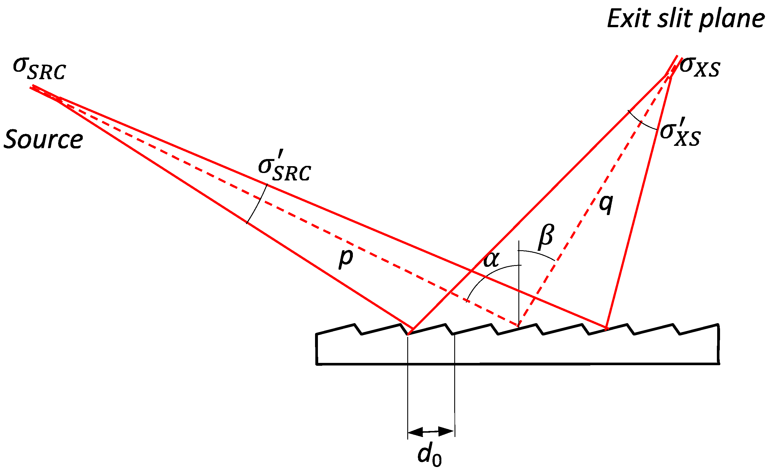
In order to analyse the problem, we consider a monochromator following the principle presented in
Figure 1. We assume that the distances between source, grating, and exit slit plane are much larger than the length of the grating. This allows considering an almost constant line density grating, for which the contribution to pulse stretching of the
D2 term can be neglected, and allows for a parallel projection of the beam cross section over the surface of the grating.
Let us consider the monochromator illuminated by a fully coherent gaussian source. It fulfills the following relationship between source size
, divergence
, and wavelength.
with
and
being the standard deviation of the intensity distribution.
In the ideal case in which the full beam is accepted by all the optical elements and no aberrations are added to it, the product of beam size and beam divergence is preserved. Therefore, there is an expression equivalent to Equation (3) for the beam at the exit slit plane.
The conservation of phase space area is valid for any optical system in paraxial approximation. The results obtained for this setup are valid for any aberration-free grating monochromator and can be extended to any system by considering the contribution of aberrations and other wavefront errors. This is done in
Section 2.3. The footprint on the grating can also be unequivocally expressed, starting from the dimension and divergence at the exit slit. It is given by a gaussian distribution with the following width:
Additionally, as before, considering that each line of the grating delays the beam by
, we have the pulse stretching as also gaussian, with a root mean square (rms) width of:
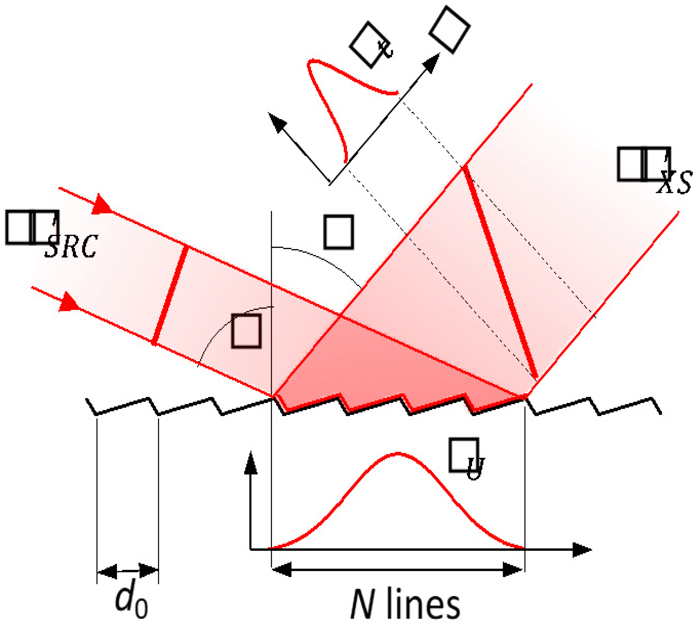
Here,
is the number of lines within one standard deviation of the intensity distribution of the footprint. It is equal to
, with
being the line density of the grating (see
Figure 2 for details). Therefore, as expected, the time stretching is proportional to the number of lines illuminated by the beam.
At the same time, the resolution limit of the monochromator (see for instance [
13]) can be calculated as:
The resolution is proportional to
, but it can also be expressed as a function of the divergence using Equation (5):
Ultimately, as a function of the footprint on the grating, and of the number of illuminated lines, using Equation (6):
The product between spectral resolution and time stretching is given by the product of Equations (7) and (10). The dependence on the number of lines cancels, and one obtains the simple relationship:
Considering that the energy of a photon is
and that
, we obtain:
This is exactly the lowest value allowed by for a distribution and its Fourier transform, which means that gaussian coherent beams provide optimal time stretching for a given resolution. It is often convenient to express the distributions in terms of their full width at half maximum (FWHM). For gaussian functions, this is done by multiplying each standard deviation by 2.35. In this case, Equation (12) becomes:
2.2. Beam Clipping
The stretching of the pulses is proportional to the number of illuminated lines. Therefore, one easy way to reduce it is to clip the beam. It can be done by using slits upstream the monochromator to have fewer illuminated lines. When this is done, the beam footprint on the grating is limited to a length L over the grating. It can be considered more or less uniform, depending on how much the beam is clipped. We analyze this case, using the same optical scheme given in
Figure 1, with the beam footprint on the grating almost uniform within
L. It means that all the
N lines (defined as
) are illuminated with identical intensity.
In this case, the image of a monochromatic source at the exit slit is produced by the diffraction due to the grating acceptance, which, in absence of aberrations, is a sinc
2() function whose width is given by:
The constant factor is used to express the width of the distribution as a FWHM. The energy resolution of the monochromator is then obtained by replacing
in Equation (8) by the expression of
in Equation (14). After simplifying factors, we obtain the following expression:
Since all the lines within the accepted length, L, are uniformly illuminated, the pulse stretching is given by a rect() function, and its FWHM length is equal to the number of lines times the delay introduced by each line, e.g.,:
Therefore, the product of resolution and pulse stretching is obtained by multiplying Equations (15) and (16):
Note that, in this case, the product is about a factor two larger than for a fully accepted gaussian coherent beam. This means that, although clipping the beam allows reducing the length of the pulse, it also degrades the spectral resolution and, of course, the flux. In this case, the product of resolution and pulse length tends, at best, to a factor 2 larger than the transform limit.
2.3. Wavefront Errors and Slit Size
In previous sections we have described the limiting cases that determine the best possible resolution obtainable by the monochromator, assuming that the exit slit aperture is negligible with respect to the spot size. This is not the case in actual monochromators, for which the slit must be open to allow having some flux. To account for the aperture of the slit, Equation (8) can be rewritten to take into account all the contributions to the resolution of a monochromator as:
Here
is the rms measure of the slit size (
ss), and
is the rms spot size of the monochromatic beam.
includes all the contributions to the spot size, like the diffraction limit, source size, figure errors, residual aberrations, vibrations, etc. The cases presented in
Section 2.1 and
Section 2.2 correspond to ideal cases without contribution of errors or aberrations. However, in reality
is always larger than the values of
obtained for these ideal cases.
The slit size, and all the errors, contribute to degrading the spectral resolution of the monochromator. However, they do not modify the pulse stretching since the number of illuminated lines is not affected by these errors. Therefore, the product between resolution and pulse length increases, which is equivalent to say that the pulse stretching becomes larger with respect to the transform-limited pulse.
While current state of the art allows for almost-negligible contribution from slope errors and aberrations, the slit size must be sufficiently open to transmit enough flux. The ratio resolution-flux is normally optimized when the slit size matches the monochromatic FWHM spot size. In this case, both terms under the square root of Equation (20) are roughly equal. The resolution and the pulse stretching are, therefore, degraded by a factor about
with respect to the values given in
Section 2.2 and
Section 2.3.
From what we have seen so far, to optimally approach a transform limited pulse stretching, one needs to meet the following requirements: (1) the source must be fully coherent; (2) the source must be gaussian; (3) there should be no appreciable aberrations or shape/slope errors of any type along the optics perturbing the wavefront; (4) the beam shall not be clipped anywhere along the beamline; (5) the exit slit must be optimally closed.
3. Monochromator Design
To fulfil the requirements defined in the first section and taking into account the discussion made in the second section, a highly modified version of a Hettrick–Underwood (H-U) monochromator [
14] was chosen. To the best of our knowledge, this design is different from any existing monochromator implemented so far. The reason resides in the very challenging requirements we had to compulsorily satisfy.
Our design is based on a Variable Included Angle Variable Line Spaced grating (VIA-VLS) monochromator working with variable convergence illumination. The X-ray beam, at the monochromator, is converging thanks to an elliptical mirror (M1) located 5.85 m upstream of the gratings. The elliptical mirror, the plane pre-mirror inside the monochromator, and the gratings are all facing up. These three optics combined provide the needed vertical beam angle of 70. The exit slit is located 19.65 m downstream of the gratings and is installed at the ceiling of the experimental hall. A beam pipe crosses the floor of the upper level, bringing the light from the exit slit to the refocusing section, and then to the experimental station.
M1, a bendable elliptical mirror, allows choosing the position of its focus downstream of the grating(s). The location of this focus varies with the grating and the operation mode. It can be continuously tuned if needed. Two other important roles are played by this bendable mirror. The first one is to compensate for the variations of the longitudinal position of the source. This is because in an FEL, the source position changes according to the mode of operation of the machine and on the photon energy of the emitted radiation. The second is related to the preservation of the pulse duration, e.g., the need for illuminating the minimum required number of lines in the grating without clipping the beam. This design permits obtaining the required resolving power with a relatively limited departure from a transform limited pulse.
To better understand the functionality of the monochromator, let us recap the basic equations used to design it. The convention adopted is the same used in [
15], with
and
being the angles of incidence and diffraction with respect to the normal, which are positive when they are on opposite side of the grating normal (see
Figure 1). The Variable Line Spacing gratings have line density
D(
x) (reciprocal of the period “d”), which depend on
x through the polynomial law:
The angle of incidence and diffraction of the gratings are defined by:
with
n being the diffraction order (set to +1 in this design). The focal conditions of a plane VLS grating can be found by solving (equalize to zero) the second term of the optical path function
F200 (also known as meridional focus). For a VLS plane grating, it corresponds to:
with
p being the distance from the source (with negative sign for a virtual source) to the grating and
q being the distance from the grating to the exit slit (or monochromatic image).
The D2 term is optimized to minimize the coma aberration. The higher orders of the groove density polynomial law (e.g., D3, D4, and so on) are not used in any optimization of this design. In fact, their contribution to the overall spot dimension is negligible, as it is in most designs. Because our design works with converging light, the source for the grating is virtual and the term p is always negative.
In a H-U monochromator, the beam incident on the grating always converges to the exit slit plane (
). This condition allows having the diffracted beam focused at the exit slit independently of the combination of angles
α and
β. Among the other advantages, this permits to scan the energy by rotating only the grating, or the mirror, being, as said, the beam always in focus at the exit slit. However, if the source distance changes, as it does in an FEL, the range at which the beam stays in focus may be limited. With the selected parameters of the gratings, presented in
Table 1, and the expected performance of the source, an energy range in excess of 100 eV can be covered without the need to either change the M1 focal distance or rotate more than one component.
The H-U other advantage is that the beam is in focus without the need to change the included angle (
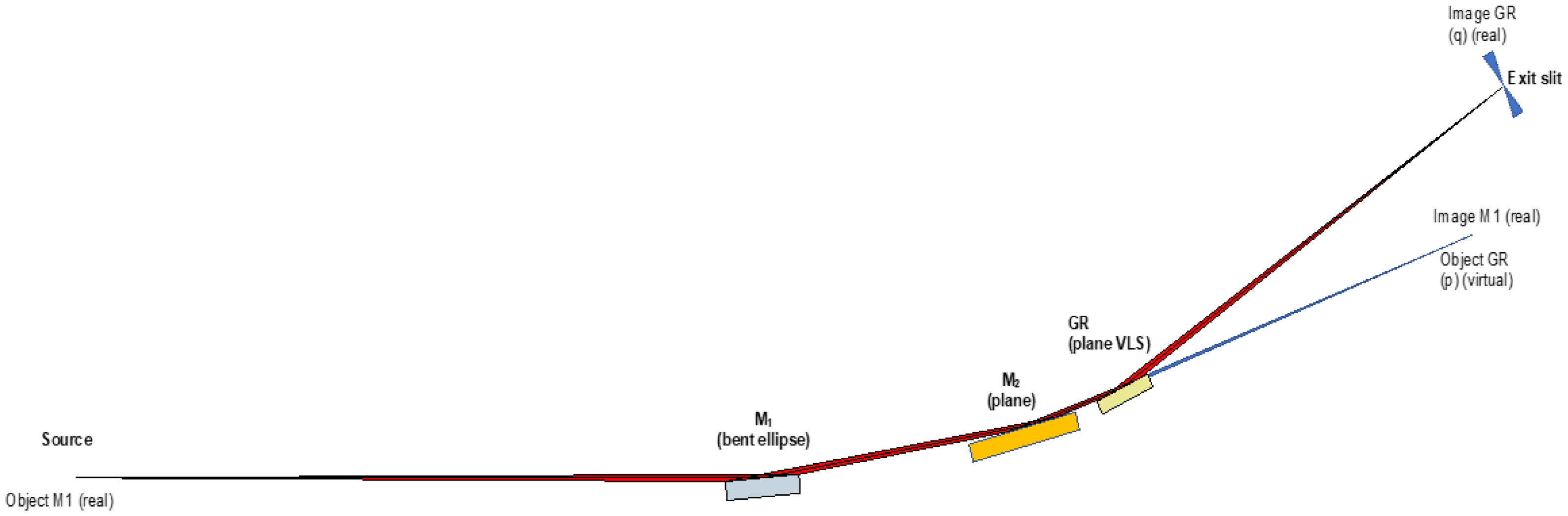
). However, having a fix focal distance for M1 implies that the footprint on the grating depends on the natural divergence of the beam and does not allow optimizing the geometry of the monochromator. In particular, at low energies, the footprint on the grating is quite large, and the beam is either clipped or temporally stretched, far away from the transform limit. In our scheme, shown in
Figure 3, the availability of the variable included angle and of an adaptive mirror (M1), which allows setting the virtual source for the grating at a desired position. This allows the control of the footprint on the grating without clipping the beam, but this minimizes the stretching. Differently to a H-U design, in this geometry, the
cff parameter (cos
/cos
) of the monochromator cannot be freely chosen, and it must fulfil the following equation to focus the beam at the exit slit plane:
To allow controlling the cff, the monochromator also includes a plane mirror, upstream to the gratings, that allows modifying the incidence angle on the gratings.
The range of possible solutions is, in principle, unlimited. It is, in practice, restricted by some constrains. They are, for instance, the available angles in the grating mechanics, the distance between the grating and the exit slit (19.65 m, determined by the experimental hall height), and the damage limit of the gratings [
7].
The imposed long separation between the grating and the exit slit is, in principle, a positive factor to achieve larger resolving power (see Equation (18)). Obviously, a large
q helps achieving a small
. However, as a drawback, such a large focal distance makes the quest for transform limited low-resolution operation more difficult. Moreover, the effect of vibrations and slope errors increase with larger focal distances. This effect plays an important role in reducing the resolution (increasing the monochromatic image). Then, of course, there is the effect of the illuminated lines. Equation (10) can be rewritten in terms of FWHM (for both the energy bandwidth and the number of illuminated lines by the beam) as:
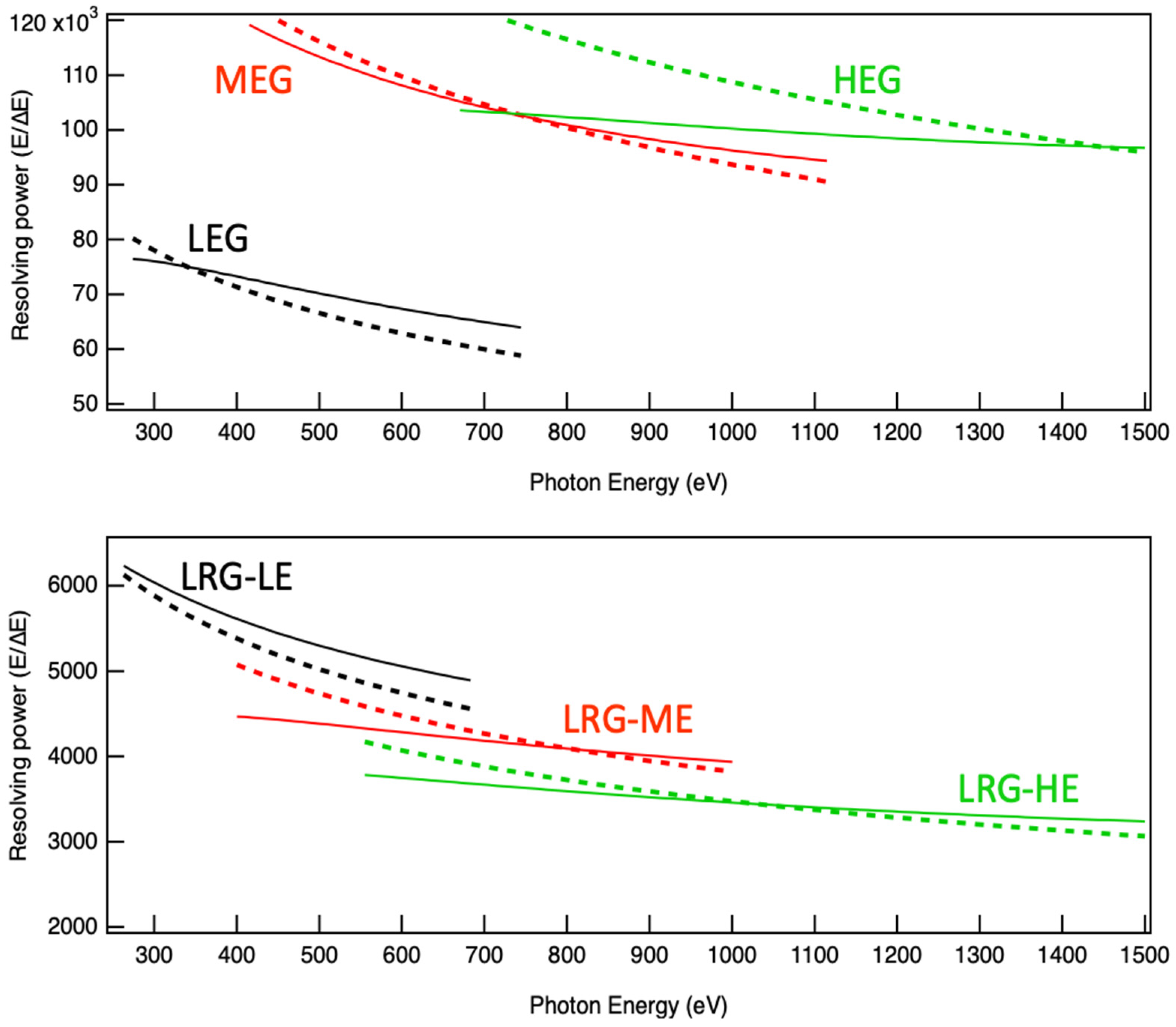
The monochromator uses a total of four gratings. Three of them are designed to reach very high energy resolution (tentatively in excess of 50,000). Namely, they are HEG (High Energy Grating), MEG (Medium Energy Grating), and LEG (Low Energy Grating). The fourth grating (called LRG, Low Resolution Grating) is used to generate a shorter pulse as close as possible to transform limited, with resolving power below 5000. It will work with three different virtual source distances, as shown in
Table 1. To achieve high resolution, the virtual source is placed at the exit slit plane for HEG and MEG. For LEG, to reduce the number of illuminated lines (the beam divergence is larger), and to maintain the grating length below 240 mm, the virtual source is set to be around 7.5 m downstream of the grating. For low resolution, the virtual source is also set closer to the grating, reducing the footprint at the grating. With a lower number of illuminated lines, the resolving power and the beam stretching are contained, still accepting the whole beam.
The three configurations of the LRG are called, without surprise, LRG-HE (HE standing for High Energy), LRG-ME, and LRG-LE (with ME being the Medium Energy one and LE the Low Energy). The parameters of the gratings are reported in
Table 1.
For the High Energy Grating (HEG) and for the Medium Energy Grating (MEG), the choice of cff is, technically, arbitrary. In fact, for any choice of cff, the grating is still focusing on the exit slit (standard H-U design). However, the need for preventing damage of the grating, and the request of having a very high resolution, without spoiling too much of the pulse length, considerably reduces the range of possible values for cff. For the other gratings, LEG and LRG (in its 3 modes), cff can only be changed together with the focal distance of M1 (e.g., p).
With all those constrains, using the parameters shown in
Table 1, the expected resolving power, considering the residual aberrations, the expected shape errors, and optics vibrations, is calculated and shown in
Figure 4.
From
Figure 4, one can note that the entire energy range, in high resolution mode, could have been covered by using only two gratings. Nonetheless, the overlap region would have been very limited and, more importantly, in an energy range of high interest for the scientific application of this beamline.
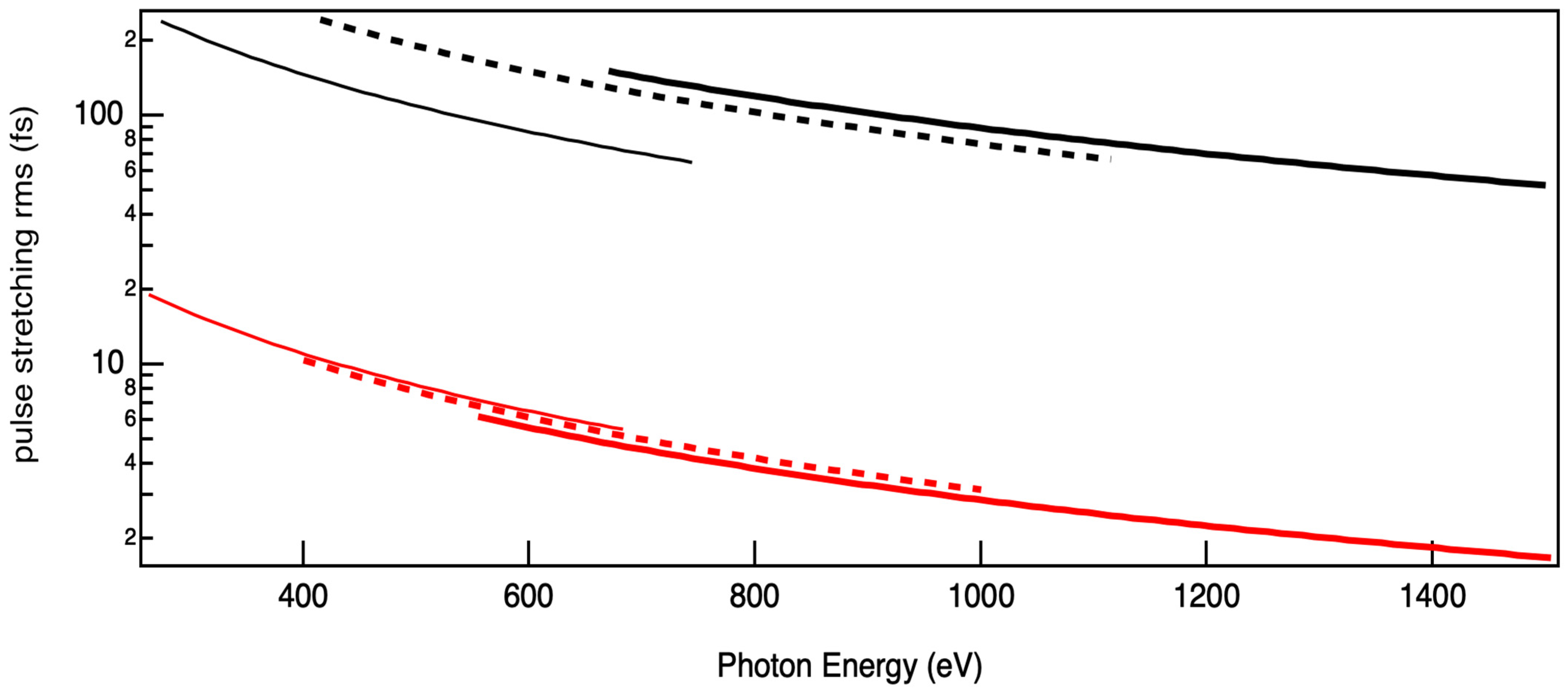
Thanks to the fact that the source is almost fully coherent, the two contributions are practically identical. With such configuration, the expected pulse stretching is shown in
Figure 5.
The ratio of the product and the transform limited value is around (almost equal contribution from the slit and from the number of illuminated lines). It is practically independent from the configuration used. This permits us to choose the resolution and the pulse duration almost freely, within the limits described earlier. Of course, the beam profile shall stay as close as possible to a gaussian and shall be completely collected by the grating.


