Article

Numerical Simulation of Heat Load for Multilayer Laue Lens under Exposure to XFEL Pulse Trains

1
Laboratory for Fluid Dynamics and Thermodynamics, Faculty of Mechanical Engineering, University of Ljubljana, Aškerčeva 6, 1000 Ljubljana, Slovenia
2
Department of Physics, Universität Hamburg, Luruper Chaussee 149, 22761 Hamburg, Germany
3
Center for Free-Electron Laser Science CFEL, Deutsches Elektronen-Synchrotron DESY, Notkestr. 85, 22607 Hamburg, Germany
4
The Hamburg Centre for Ultrafast Imaging, Luruper Chaussee 149, 22761 Hamburg, Germany
5
Laboratory for Simulation of Materials and Processes, Institute of Metals and Technology, Lepi pot 11, 1000 Ljubljana, Slovenia
*
Author to whom correspondence should be addressed.
Photonics 2022, 9(5), 362; https://doi.org/10.3390/photonics9050362
Submission received: 1 May 2022 / Revised: 19 May 2022 / Accepted: 20 May 2022 / Published: 22 May 2022
(This article belongs to the Special Issue XUV and X-ray Free-Electron Lasers and Applications)

Abstract

:
Multilayer Laue lenses (MLLs) made from WC and SiC were previously used to focus megahertz X-ray pulse trains of the European XFEL free-electron laser, but suffered damage with trains of 30 pulses or longer at an incident fluence of about 0.13 J/cm2 per pulse. Here, we present numerical simulations of the heating of MLLs of various designs, geometry and material properties, that are exposed to such pulse trains. We find that it should be possible to focus the full beam of about 10 J/cm2 fluence of XFEL using materials of a low atomic number. To achieve high diffraction efficiency, lenses made from such materials should be considerably thicker than those used in the experiments. In addition to the lower absorption, this leads to the deposition of energy over a larger volume of the multilayer structure and hence to a lower dose, a lower temperature increase, and an improved dissipation of heat.

Graphical Abstract

1. Introduction

X-ray free electron lasers (XFEL) provide intense, coherent, pulsed X-ray beams and have opened up new scientific fields, including the single-shot imaging of biological samples, imaging the dynamics of matter, creating matter under extreme conditions and studying nonlinear X-ray optical processes. The short wavelengths and short durations of XFEL pulses mean that these studies can be performed with a nanometer spatial resolution and femtosecond temporal resolution. Two-photon processes such as nonlinear Compton scattering [1] or two-photon absorption [2] are dependent on the square of the X-ray intensity and thus are best observed at the highest intensities (high numbers of photons per area and time). High intensities are also needed for single-molecule diffractive imaging [3,4], generating stimulated X-ray emission [5], and for utilizing the interference of fluorescence photons for imaging [6].
To reach the highest X-ray intensities, XFEL beams must be focused. This can be achieved using refraction (compound refractive lenses or CRLs) [7,8,9], reflection (Kirkpatrick-Baez mirrors) [10,11] or diffraction (zone plates) [12,13]. We recently explored the focusing of the X-ray beam of the European XFEL (Schenefeld, Germany) using a pair of multilayer Laue lenses (MLLs) [14]. These multilayer-based diffractive optics consisted of refractory materials (silicon carbide and tungsten carbide) [15], which, although absorbing some X-ray energy, offered high thermal stability. No change in the multilayer structures made out of these materials was observed when heating them up to 1073 K in the laboratory [16]. Given the aim to focus as large a proportion of the XFEL beam as possible, the beam size should be matched to the cross-sectional area of the lenses, which should be as large as possible to reduce the incident X-ray fluence. The cross-section of the MLLs was about 100 μm × 100 μm. These MLLs are among the largest ever made. Nevertheless, at this beam size, a pulse energy of 1 mJ would provide a fluence of 10 J/cm2, which would be expected to heat such lenses to close to the melting temperatures of their constituent materials, as calculated below. The European XFEL produces trains of pulses in which femtosecond-duration pulses are separated by as little as 220 ns. In the XFEL experiments, limits were observed as to how many pulses could be tolerated and it was seen that excessive exposure caused lenses to break from their mount [14]—presumably due to the heat dissipating through the weakest part of the structure or due to high stresses caused by large temperature gradients.
As is true for CRLs and zone plates, materials of a low atomic number (low-Z) should be less absorbent and thus may tolerate higher fluences than the materials used in the experiments. However, achieving high diffraction efficiency for low-Z materials requires lenses that are thicker, which also determines the absorption qualities. Different materials have a different heat capacity and thermal conductivity. Therefore, we need to investigate the optimal design of MLLs for use with XFEL pulses, including the choice of materials and structure of the lens and mounts, considering both the optical performance and the thermal management. Here, we present the results of numerical simulations in which we calculated the heat load on the MLLs of various geometries and materials. We validated and benchmarked these results against the geometry and materials used in the aforementioned European XFEL experiment. After a short description of MLLs and their preparation, we define the geometric model, computational grid, material properties, boundary conditions and determine the optimum mesh size. In the results and discussion section, we display MLLs temperature distribution plots and study the time dependence of the temperatures for all studied geometries. A simulation showing time evolution at different absorbed energies for two selected geometries is also presented. Finally, we calculate vertical temperature profiles in the lenses. We present a promising MLL design based on materials and geometry that reduces the X-ray dose in the structure (energy deposited per unit mass) and effectively dissipates the heat. The lens design is considered for future experiments at the European XFEL using full unattenuated pulse trains.

2. Multilayer Laue lenses

2.1. Fabrication of MLLs and Their Use at the European XFEL

An MLL is a volume zone plate sliced from a structure prepared by layer deposition onto a substrate [17]. The thicknesses of the layers are made to follow the zone plate equation, in which the layer period varies inversely with distance from the optical axis to diffract light to a common focus. However, this alone is not sufficient to achieve high efficiency. The layers must also be wedged so that the tilts of the layers satisfy Bragg’s law [18]. An MLL cut from a structure deposited onto a flat substrate can focus X-rays only in one dimension, similar to a cylindrical lens or mirror. Two such elements oriented orthogonal to each other are needed to produce a two-dimensional focus. Both MLLs must be optimized for the same photon energy but with slightly different focal lengths so they can be placed one after the other and focus on a common plane.
Multilayer structures from which MLLs were prepared were deposited by magnetron sputtering in our laboratory [19]. The multilayer consisted of alternating layers of silicon carbide (SiC) and tungsten carbide (WC), materials that have been used previously [20] and with melting temperatures of ~3073 K. We found that multilayers consisting of these two materials are thermally stable up to the highest tested temperatures by heating in an oven to 1073 K [16]. The multilayer structure (100 µm tall) consisted of over 20,000 layers, following a design to produce a focal length of 8 mm at 10.1 keV. A straight-edge mask was placed above the substrate during deposition to create the wedged structure by shadowing, and the MLLs were cut at the particular position where the wedge angle matched twice the focal length [20]. These cuts were performed using a focused ion beam (FIB) to create MLLs that were about 100 µm tall, 125 μm wide and 4.5 μm thick in the beam direction, as shown in Figure 1. For rigidity, the lenses were cut to leave narrow posts 10 µm wide on either side. We refer to this geometry as G1a. Ideally, the lens pair would have a cross-sectional area as large as the unfocused XFEL beam, which is typically several hundreds of micrometers wide. However, it is challenging to make MLLs, consisting of nanometer-thick layers, much taller than about 100 μm. Each lens was attached to the edge of a 100 µm thick diamond wafer and adhered to it using electron-induced deposition of Pt in the focused ion beam system (as shown in Figure 1). Diamond was chosen due to its low X-ray absorption and superior heat conduction.
The MLL design with an 8 mm focal length and 100 µm height gave a numerical aperture of 0.006 at 10.1 keV to ideally focus X-rays of this energy to a spot of 15 nm full width at half maximum (FWHM). The wavefronts of the lenses were measured [21] and found to be dominated by coma with an RMS error of about 1.5 waves, caused by layer placement errors. The achieved focus, as determined from the wavefront, was 25 nm FWHM [14].
Experiments were performed at the MID [22] beamline of the European XFEL at 10.1 keV photon energy with a relative bandwidth of 0.1% [23]. The lenses were in an air environment at atmospheric pressure with no active cooling during the experiment. The XFEL beam illuminating the lenses was larger than the lens cross-section even though it was already prefocused and defined with slits. Hence, not only the lens but also the supporting structure, namely the substrate and the attachment points (Pt dots), were exposed.
The alignment of the MLLs was achieved using the same procedure as at the synchrotron [15], except that the beam was highly attenuated. Once aligned, the pair of MLLs was initially used to focus the XFEL beam operating in a single-pulse mode (that is, at a 10 Hz repetition rate) and 92% beamline transmission for 6 h with no adverse effects on the lenses. The incident fluence on the first lens was estimated to be about 0.5 J/cm2. We then increased the number of pulses per train to 2, 3, 4, and 5, all with a pulse separation of 3.56 µs and the same 92% beamline transmission. We continued increasing the number of pulses per train to 6, 7, 10, 20, and 30 but, in this case, only to a maximum beamline transmission of 23.5%. The final experiment was performed with 30 pulses per train and with 23.5% transmission. At this condition, the lenses were brought out of the Bragg condition by the action of the beam, reducing their diffraction efficiency, and causing the lenses to break off the substrate they were attached to. We suspect this was caused by an excessive heat load on the lenses and the weak lens mounting. It is therefore seen that the damage threshold with single pulses of 10 Hz was not exceeded at an incident fluence of about 0.5 J/cm2 but was exceeded with 30 pulses per train at about 0.13 J/cm2.

2.2. Dynamical Diffraction of MLLs

The diffraction of X-rays by the multilayer structure of an MLL can be described by the theory of dynamical diffraction [24]. Locally, a beam of wavelength λ can be considered to be interacting with a structure of period d, which gives rise to the following two transmitted beams: one that is deflected by an angle 2 θ (determined by Bragg’s law, λ = 2 d sin θ ) and one that is undeflected. The convention is to call the former the reflected beam since it appears to reflect from the layers, and the other the refracted beam [25]. The period d changes with position y in the MLL to ensure that the deflection angle increases with y such that the reflected rays are directed to a common focus. For given materials, the fraction of the incident beam that is split into the reflected (focused) and refracted beams depends on the thickness of the MLL in the direction of the beam, as shown in Figure 2. The optimal thickness is equal to half of the so-called pendellosung period, for which almost the entire proportion of the transmitted beam is in the reflected beam. An approximate expression for this is given by
τ opt = π λ cos θ 4   Δ n
where Δ n is the difference in the real parts of the refractive indices of the two-layer materials. Away from the absorption resonances of the materials, the refractive indices scale with λ 2 and hence the optimal thickness tends to increase inversely with wavelength or linearly with photon energy.
To first approximation, the X-ray energy absorbed in the MLL by an incident beam of energy Q 0 , can be calculated from the attenuation of X-rays by a slab of material of thickness τ and an average composition of the two layers, as
Q abs = Q 0 ( 1 e μ A   ρ   τ )
where μ A is the mass absorption coefficient (photo-absorption cross-section per unit mass), such that the volume-averaged attenuation coefficient is μ A   ρ = 4   π   β ¯ / λ   for an average imaginary part of the refractive index β ¯ = ( Γ   β 1 + ( 1 Γ )   β 2 ) . Here, β 1 and β 2 are the imaginary parts of the refractive indices of the two materials, and Γ is the fraction of the layer thickness of the first material (typically Γ = 0.5 ). Since the thickness of MLLs obtained from Equation (1) is usually less than 1 / μ , Equation (2) can be approximated as Q abs = Q 0   μ A   ρ   τ and hence the energy absorbed in an MLL of optimized thickness τ opt is proportional to the ratio β ¯ / Δ n , which can be minimized by choosing materials of low atomic number. However, for a given specific heat capacity c p of the MLL structure, the instantaneous heat rise due to an instantaneous X-ray pulse of fluence I 0 = Q 0 / A , for a cross-sectional area of the beam A, would be given by
Δ T = Q abs V   ρ   c p = I 0   μ A   c p
where the volume V = A   τ . The temperature rise, similarly to the dose (energy absorbed per unit mass), does not depend on the actual thickness of the lens but just on its optical and material properties, which are dependent on the photon energy. Under the approximations made thus far, the lowest heating would be achieved by choosing materials with the lowest photo-absorption cross-section and the highest specific heat capacity. Some of the properties of the materials used in the calculations and simulations of this paper are listed in Table 1 [26,27,28].
Equation (2) assumes a uniform structure of the average composition of the MLL and does not account for the fact that the wavefield is diffracting in the structure. The reflected and refracted beams mentioned above form a standing wave in the periodic structure. When the nodes of this standing wave are located in the more absorbing layers, then the beam is attenuated less than expected from Equation (2), known as the Bormann effect [25]. In such a condition, less energy is absorbed in the structure than predicted by Equation (2). In crystals, this occurs when the structure is oriented relative to the incident beam to produce the highest possible reflected intensity [25] but is not necessarily the case for multilayer structures [29]. The magnitude of this effect depends on the ratio Δ β / β ¯ , which means it is significant when one of the layer materials is much more absorbent than the other. However, we find that for all materials pairs we studied, Δ β is not large enough to increase the transmission at the condition of maximum reflectivity. Figure 2b shows the proportion of incident energy into the reflected and refracted beams, the total transmission (given by the sum of reflected and refracted beams), as well as the prediction of Equation (2), all for a WC/SiC MLL at an 8 keV photon energy. This result, similar to that with other material pairs and photon energies, shows that anomalous transmission does occur but only off the peak of the reflected beam as a function of the incident angle, at angles where there is significant partitioning into the refracted beam. At the maximum point of the reflected (focused) beam, Equation (2) is seen to apply.
In Table 2, we provide values of the optimum thicknesses (Equation (1)), the absorbed energy (Equation (2)), dose (in units of kGy = kJ/kg) and the instantaneous temperature rise (Equation (3)) for MLLs constructed from various materials and for various photon energies, using mass absorption coefficients determined from tabulated optical constants [30] and the material properties are shown in Table 1. The incident fluence was assumed to be 10 J/cm2, or 20 times the fluence of the XFEL experiments. As mentioned above, the dose and temperature rise are dictated by the mass absorption coefficient (an intrinsic property). Away from the absorption edges (atomic resonances), this coefficient varies approximately with the inverse square of photon energy, roughly the trend seen for calculated dose and temperature rise in the case of B4C/SiC. It is not the case for WC/SiC, where the temperature rise appears to vary inversely with photon energy. This is because the atomic L edges of W are at 10 to 12 keV.
As expected, the calculated temperature rise is lowest for MLLs constructed from materials of a low atomic number, such as B4C/SiC and Be/SiC. Most of the materials considered have relatively high heat capacities, leading to low-temperature rises. WC has one of the lowest heat capacities. Even so, it has a high melting temperature that is larger than the calculated temperature rise for this particular incident fluence. The failure observed in our experiments was not caused by a single pulse but by an accumulation of heat which could not quickly dissipate during the pulse train.

3. Numerical Simulations

Table 2 provides estimates for the instantaneous heat rise caused by a single XFEL pulse, but the response of the MLL to a pulse train depends on how fast heat is dissipated between pulses. This depends not only on material properties such as conductivity and emissivity but also on the particular geometry of the lens and its mounting structure. Numerical simulations have proven to be an effective tool for solving heat transfer problems [31,32,33] when the geometry of the problem or boundary conditions are too complex to use analytical methods. One can quickly analyze the effect of several geometric variants and the influence of different boundary conditions. They also give a broader picture of the problem under consideration. Nilsson et al. [34,35] used the alternative finite element method (FEM)-based software COMSOL [36] for solving the transient heat equation in the case of heat transfer in zone plate optics exposed to XFEL. Here, we carried out simulations with computational fluid dynamics (CFD) software ANSYS Fluent [37] which is based on the control volume method (CVM). The code is widely used and thus validated for many engineering and natural science problems, including heat transfer by conduction, convection and radiation.

3.1. Governing Equations and Solution Procedure

In the following, we present the basic equations that describe the geometry and physics that need to be considered for the evolution of heating. In the presented numerical simulations, we solve the transient heat energy transport equation (heat conduction) in solids [38,39]. The diffusion equation governs the problem
t ( ρ h ) = ( k T ) + S h
where h = T r e f T c p d T is the mass-specific sensible enthalpy, c p is mass-specific heat, ρ is the density, k is the thermal conductivity, T is the temperature, T r e f is the reference temperature and S h is the volumetric heat source. The following formulations and parameters were used in Fluent [40]: transient time formulation with second-order implicit discretization, least-squares cell-based spatial discretization for gradient, and second-order spatial discretization for energy.
In the calculation, the time-stepping method utilized a scheme for time step size Δ t : 10−7 s in the first 1000 time steps, 10−6 s in the next 900 time steps, and 10−3 s in the final 99 time steps. Such a small time step is needed at the beginning of the simulation because the time between two consecutive X-ray pulses was 3.56 × 10⁻⁶ s. The characteristic time for thermal diffusion in the WC/SiC MLL is t d i f f = L 2 / a , is 3.4 × 10⁻⁴ s, since the typical MLL dimension L is 100 µm and a = k / ( ρ c p ) is the thermal diffusivity given in Table 1. The total simulation time was 0.1 s, representing the time between two consecutive pulse trains. The steady-state temperature conditions in the MLL were reached well before the next X-ray pulse train arrived. A maximum of 20 linear solver iterations were allowed in each time step. The CPU time for one simulation was about 2 h on a 28-core Supermicro workstation (2× Intel® Xeon® CPU E5-2690 v4 @ 2.60 GHz).

3.2. Geometric Model and Computational Grid

We used numerical simulations for the following two purposes: (a) to estimate the evolution of the heat load for the existing lens, and (b) to explore other materials and geometries that might be better suited for focusing XFEL pulses with MLLs. The general model was created using the Gambit [41] mesher and is presented in Figure 3.
The model was assembled from three parts, namely an aluminum holder, a diamond plate, and the MLL consisting of a silicon substrate and a multilayer structure. The MLL geometries are designated G1a, G1b, G1c and G2a, and G2b (Figure 4).
The MLL geometry used in the XFEL experiment was G1a, with a lens thickness of 4.5 µm, which is the optimum thickness for a WC/SiC multilayer used at a photon energy of 8–10 keV (first row of Table 2). Its variant G1b has 10-times wider side columns (100 μm vs. 10 μm wide) as part of the monolithic structure assumed to be cut from the deposited multilayer. Variant G1c is approximately 10 times thicker in the X-ray beam direction (45 μm vs. 4.5 μm). This would correspond to an optimum thickness of a lens consisting of a B4C/SiC ML and used at 8 keV photon energy. For a given incident fluence, Table 2 shows that this lens absorbs about the same amount of energy as the thinner WC/SiC lens, although it is distributed over a larger volume. The G2a geometry is a proposal for a new lens shape with an improved attachment to the diamond plate, with the same 4.5 µm lens thickness as G1a. The variant G2b is similar but with a lens thickness of 45 μm (for B4C/SiC ML). The G2 variants had an increased area of attachment to the diamond mount, with the aim to improve the conduction of heat out of the lens. Due to the significant difference in the dimensions of the holder (cm-scale), plate (mm-scale) and lens (μm-scale), each part was meshed separately. Because these parts have different cell sizes, a non-conformal mesh interface was used to assemble the final computational mesh.

3.3. Material Properties and Boundary Conditions

Table 1 summarizes the properties of the materials used in the numerical simulations [26,27,28]. Due to the lack of reliable data on the temperature dependence of material properties, especially emissivity, constant values were used in the simulations.
To solve Equation (4), the combined external convection and radiation thermal boundary condition were used. The wall heat flux is given by the following equation
k T n = α ( T T ) + ε σ ( T 4 T 4 )
where α = 20   W / ( m 2 K ) is the heat transfer coefficient, ε is surface emissivity (Table 1), σ = 5.67 × 10 8   W / ( m 2 K 4 ) is the Stefan-Boltzmann constant, and T = 296   K is the ambient temperature.
Our first set of simulations presented below in Sec. 4 were made to explore the effect of the geometry of the lens and its mounting on the ability to dissipate heat and tolerate high-intensity pulse trains. For this, we considered a particular absorbed energy of Q a b s = 15.6 µJ even though the absorbed energy for a given X-ray fluence would differ for different materials and geometries.
This choice of Q a b s corresponds to an incident pulse energy of 41.3 µJ for a WC/SiC lens of 4.5 µm thickness in the G1a or G1b geometries. This is approximately equal to the estimated absorbed energy per pulse in the XFEL experiments. The source term due to each absorbed X-ray pulse, needed as the input for Equation (4), is S h = Q a b s / ( V Δ t ) , is listed in Table 3 for the various geometries, and for the same multilayer material pair of WC/SiC. The time step for the consideration of the source was Δ t = 10 7 s .
This is considerably longer than the femtosecond duration of the X-ray pulse, but it is assumed that heat does not transfer between mesh nodes within this time. Each X-ray pulse causes a temperature rise given by Equation (5) and specific enthalpy rise (or dose) Δ h = c p Δ T , as listed in Table 3. The initial temperature of the whole domain was set to the ambient temperature.

3.4. Mesh Sensitivity Study

As a standard procedure in numerical simulations to achieve results independent of the mesh [42,43], we conducted a sensitivity study of the effect of domain discretization (computational cell size) on the results. Coarse, medium and fine meshes were created, as shown in Figure 5. For each finer grid, the cell size Δ was halved in each coordinate direction, representing an 8-fold increase in the number of the cells Nc (Table 4).
Two parameters, listed in Table 4, were used to compare the numerical simulation results for all meshes. One is the primitive variable Tmax, representing the maximum temperature reached by the MLL. The other parameter is the integral variable htr, representing the total heat transfer rate and is obtained by integrating the total surface heat flux over the MLL surface. Figure 6 shows the maximum temperature in the MLL (WC/SiC) over time. The peak was reached after 20 X-ray pulses (since we are assuming trains of 20 pulses). It can be seen from this sensitivity study that the results for the medium and fine meshes are very close. Hence, further numerical simulations were performed with the medium computational mesh due to the lower computational demands than the fine mesh.

4. Simulation Results and Discussion

4.1. Comparison of Geometries and Materials for a Constant Absorbed Energy Per Pulse

In the following, we present the results of the numerical study of the heating of MLLs using the model described above and with an absorbed energy per pulse of Q a b s = 15.6 µJ, similar to the experimental conditions, as well as for higher absorbed energies. In particular, we studied the responses of different lens geometries, mounting, and materials, under various XFEL beam conditions (intensity, number of pulses, etc.).
The numerical simulations predict that each XFEL beam pulse causes a huge instantaneous and volumetrically uniform heat load on the MLL (Equation (5) and Table 3). 
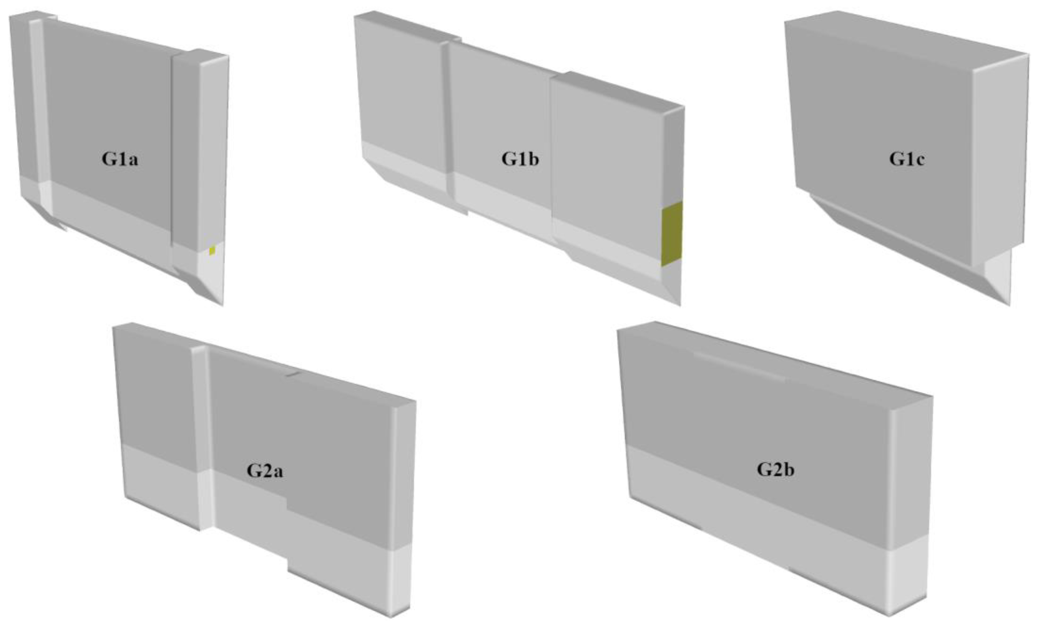
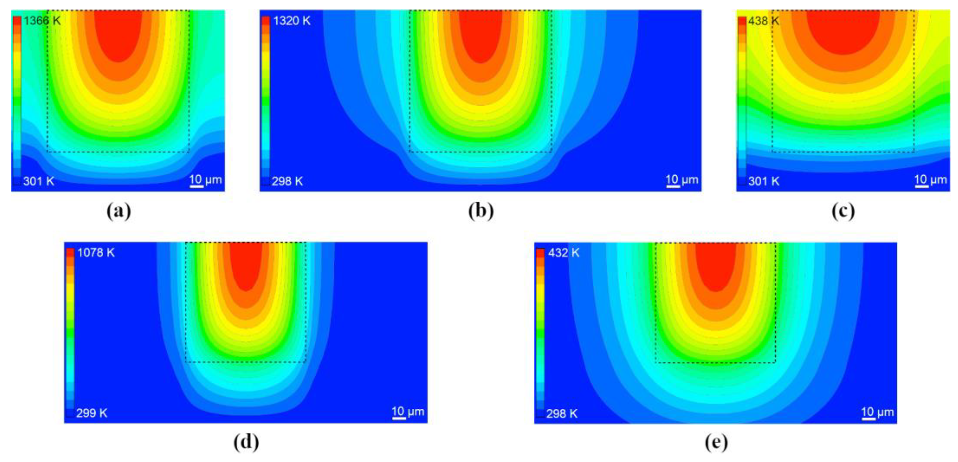
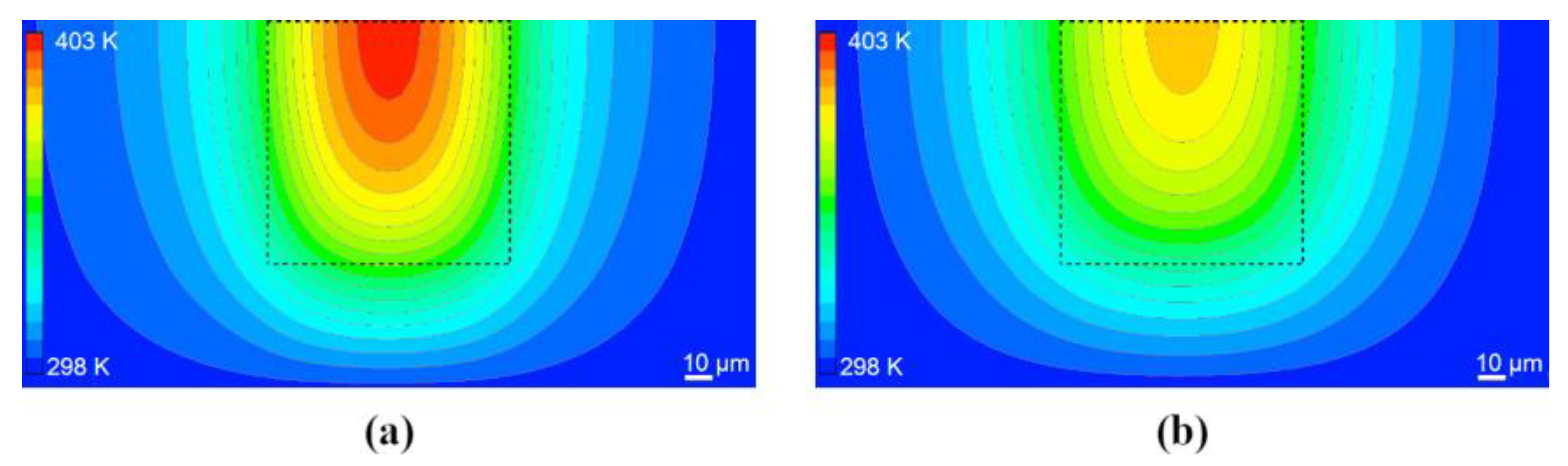
Figure 7 shows the simulated temperature field in a vertical plane perpendicular to the X-ray beam direction and intersecting the center of MLL, at a time t = 72   μ s (after 20 X-ray pulses) for all considered geometric variants, assuming the same absorbed energy Q abs = 
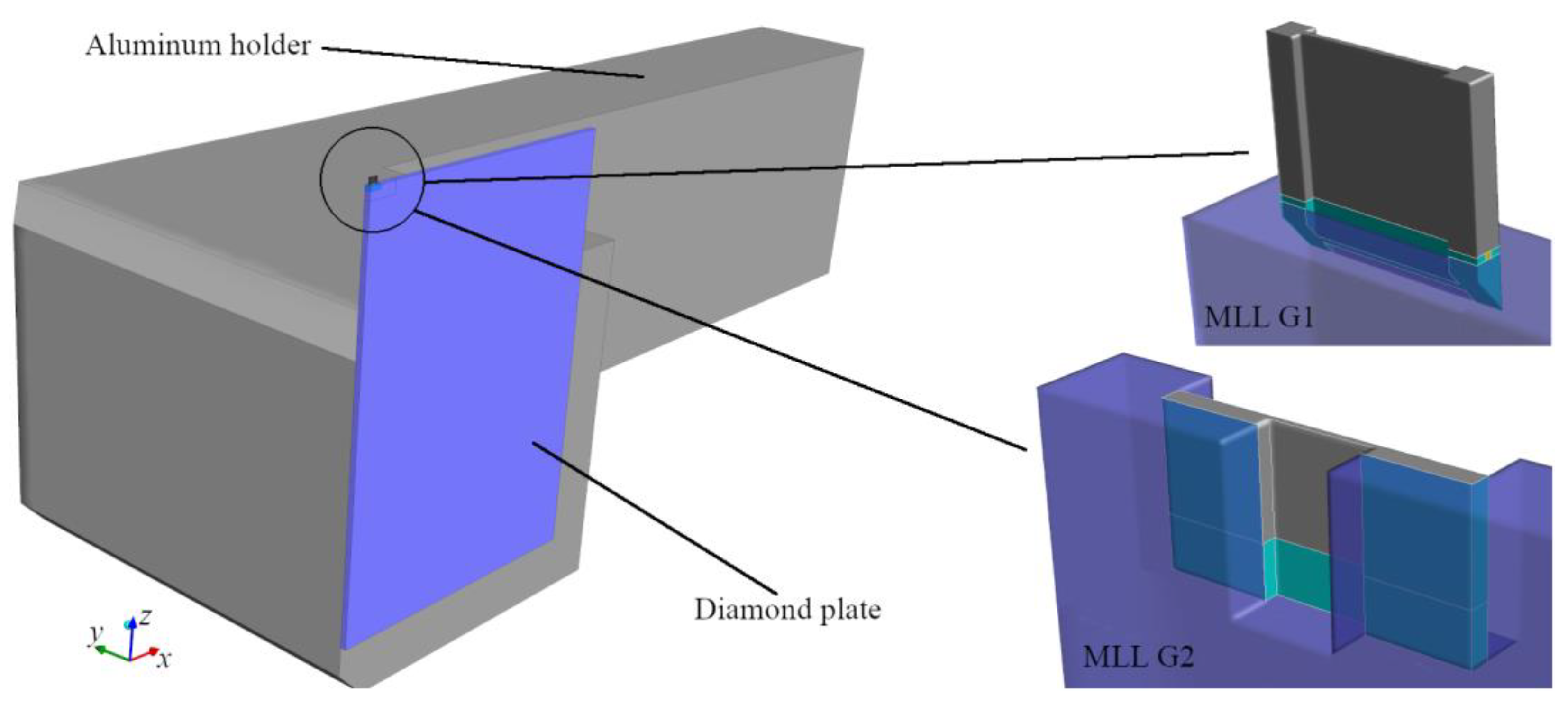
15.6 µJ and that all lenses consist of WC/SiC multilayer. As expected, the thermal load of the MLL was reduced by increasing the support structures (G1b vs. G1c) or by using a new mounting method (G2a vs. G1a). The thicker lenses (G1c and G2b) had a substantially reduced temperature simply because the energy was absorbed in a larger volume, and thus the dose was lower. The temperature field distributions show some differences for the different geometries. In the geometries G1b, G2a and G2b, the temperature distribution in the central (illuminated) part is similar to G1a, since the X-ray beam cross-section absorption area is the same. However, G1b had a larger volume of support columns, which reduced the temperature in the entire lens due to improved heat conduction and surface radiation to the surroundings. A similar effect was achieved with G2a and G2b, where the contact area between the lens and the diamond plate increased, except that the heat dissipation was even better, and thus the temperatures were further reduced. The distribution for G1c differs most from the temperature distribution for G1a. This is due to the reduced dose caused by distributing the energy over a larger volume. Note that for a given X-ray pulse fluence, the dose (an intrinsic property) is independent of thickness and thus the absorbed energy, but the optimal thickness for focusing efficiency is dictated by the materials and photon energy, so the thickness is not a parameter that can be chosen arbitrarily. Here, we can infer that a B4C/SiC MLL of 45 µm thickness (listed in Table 2) heats to a much lesser extent than a WC/SiC MLL of optimal thickness.
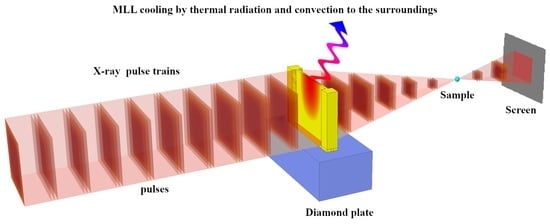
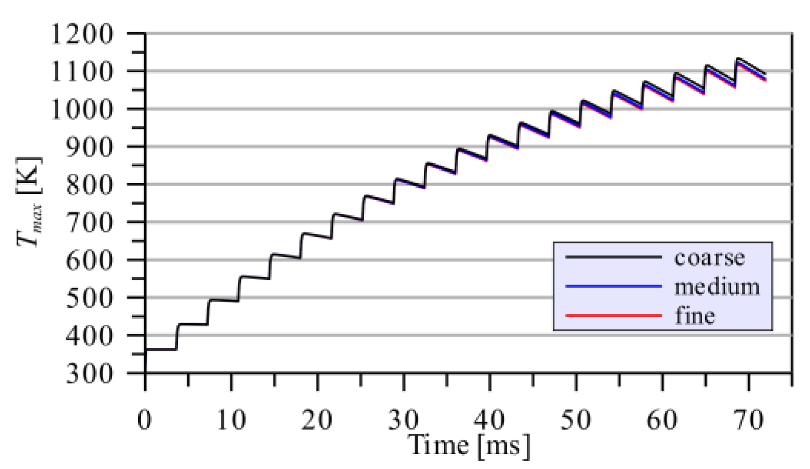
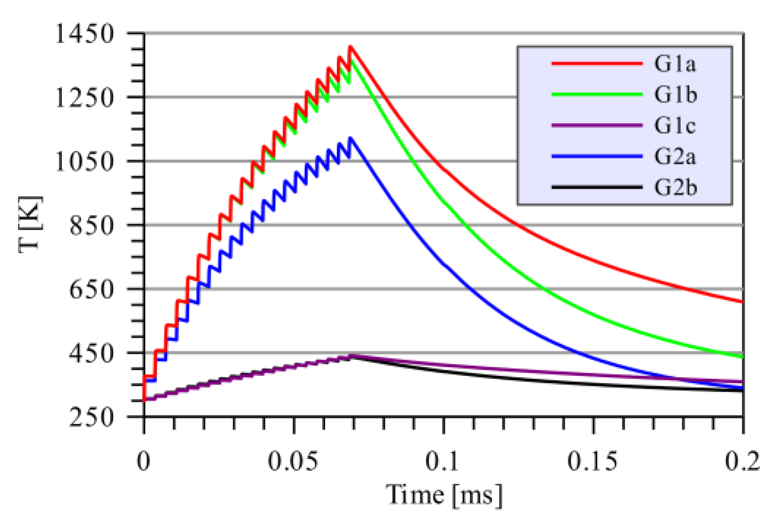
Figure 8 shows how the temperature in the hottest part of WC/SiC MLLs changed with time. The absorbed energy per pulse was taken to be 15.6 µJ. The first 200 µs are displayed so that the temperature evolution between the X-ray pulses (3.56 µs apart) as well as between pulse trains (100 ms apart) is visible. As we can see, the lens did not cool significantly between two pulses near the beginning of the pulse train when the materials were still at a low temperature. At these lower temperatures, the predominant mechanism of heat transfer is convection. With each pulse, the temperature rises stepwise, according to Δ T from Table 3. When the temperature exceeds about 573 K, the mechanism of heat transfer by radiation starts to prevail, such that in 3.56 μs the temperature of the lens drops by a considerable fraction of the rising temperature. As the temperature rises, this process becomes even more pronounced. Thus, between the penultimate and last pulse, the decrease in the lens temperature was 314.3 K for geometry G1a.
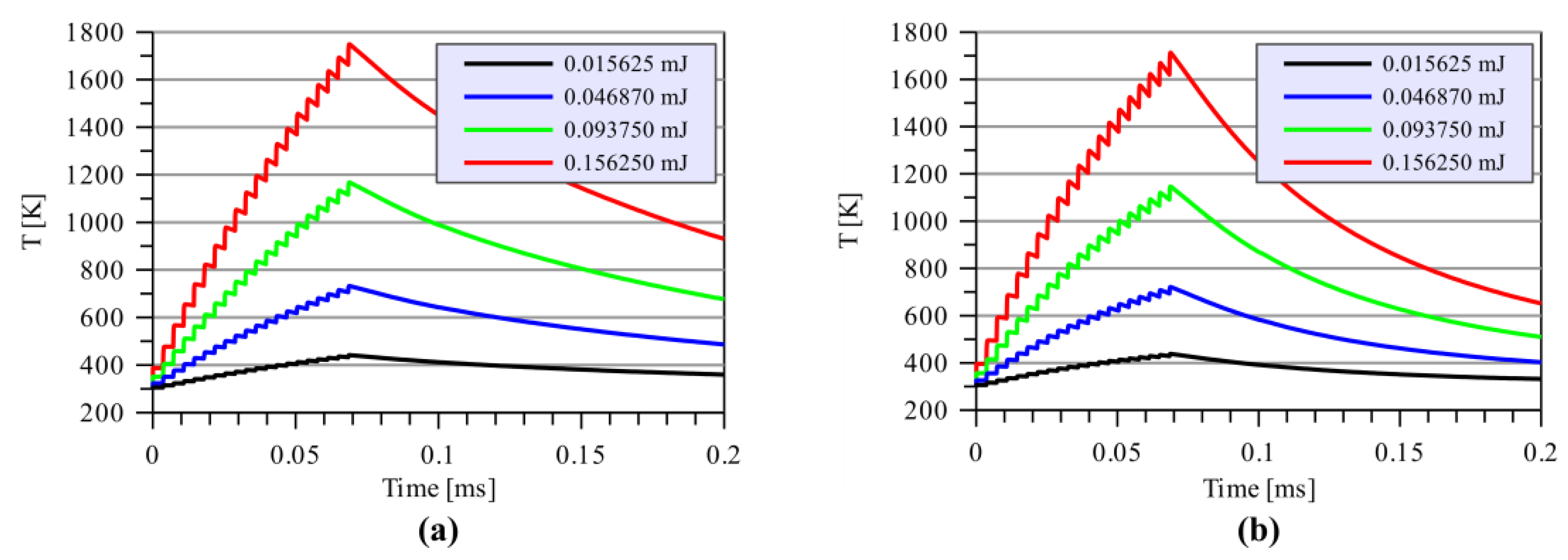
As we observed from the simulations of the thick lenses (geometries G1c and G2b) and anticipated from Table 2, the maximum temperature was considerably lower for thick lenses (Table 5), indicating that they can therefore tolerate much higher incident absorbed energies and possibly higher incident pulse fluences. As a result, we conducted numerical simulations for the geometries G1c and G2b for absorbed energies ranging from 0.0156 mJ to 0.156 mJ (see Figure 9 and Table 6).
T m a x [ K ]
These allow us to find the dependence of the maximum lens temperature after 20 pulses on the absorbed energy per pulse. For data from Table 6, the linear regression curve is
T m a x = c   Q + T
where c = 9293.52   K / mJ for geometry G1c, and c = 9065.09   K / mJ for the G2b geometry with WC/SiC multilayers. The goodness of fit is R 2 = 0.997 . If we know the maximum allowable temperature, we can calculate from Equation (6) the highest possible absorbed energy, and thus the tolerable incident pulse energy, for a particular lens design.
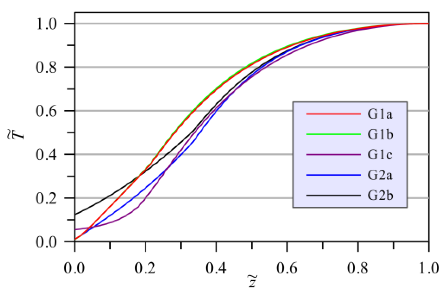
The vertical temperature profiles T ˜ ( z ˜ ) through the MLL center after 20 X-ray pulses are presented in Figure 10 as a function of the dimensionless temperature defined as T ˜ = ( T T ) / ( T m a x T ) and the dimensionless vertical coordinate defined as z ˜ = ( z z m i n ) / ( z m a x z m i n ) . The coordinate system refers to the one shown in Figure 3. Dimensionless quantities were used for ease of comparison, as the lens heights were different for geometries G1 and G2, and maximum temperatures also varied by an order of magnitude between cases. The minimum and maximum z coordinates of the MLL are z m i n and z m a x , respectively. Geometry G2b was the most favorable since it led to the smallest temperature difference. Consequently, the stresses, and thus the deformations, due to the heat load, are also expected to be the smallest.
However, the thick-lens geometry of G2b is not suitable for WC/SiC MLLs since it would not efficiently focus X-rays. As shown in Equation (1), the optimal thickness is inversely proportional to the refractive contrast Δ n of the materials. The contrast between WC and SiC is high, giving an optimal thickness of only 4.5 µm at 8 keV. The optimal thickness is much higher for the materials Be/SiC and B4C/SiC, as well as for higher photon energies, as seen in Table 2. The thickness of 45 µm is close to the optimum for B4C/SiC at 8 keV and Be/SiC at 17.5 keV photon energy. We simulated these multilayer combinations for the G2b geometry with the same absorbed energy of 15.6 µJ, 20 pulses per train and 3.56 μs separation between the pulses. This absorbed energy was caused by an incident pulse energy of 409 µJ for Be/SiC and 59.2 µJ for B4C/SiC. The temperature distribution for the two cases is shown in Figure 11, and Figure 12 compares the evolution of the maximum lens temperature over the course of the pulse train. The highest temperatures for these B4C/SiC and Be/SiC MLLs were considerably lower than for the cases discussed above, even though the incident X-ray pulse fluences were higher. For Be/SiC at 409 µJ incident pulse energy, the highest temperature is 401.47 K, and for B4C/SiC at a 59.2 µJ incident pulse energy, the highest temperature reached was 383.71 K. It is predicted, therefore, that Be/SiC MLLs can withstand higher fluence pulses than B4C/SiC or WC/SiC MLLs.
Figure 11 also shows a benefit of the 100 µm wide supporting posts for these particular materials. Because of the greater thickness of the lens there, more conduction of heat occurred transversely. In this case, the support posts acted as a heat sink, as can be seen from the temperature outside the illumination area as defined by the dashed lines in Figure 11 as compared with the much higher temperature gradients that occurred for the thinner WC/Sic MLLs depicted in Figure 7.

4.2. Comparison of Optimized MLLs of Different Materials

We also calculated the highest average and maximum temperatures of lenses made from different multilayer material pairs given in Table 2, for a photon energy of 17.5 keV, the G2 geometry, and an incident pulse energy of 1 mJ. The thicknesses of the lenses were set to their optimal values τ o p t given by Table 2. The incident energy of 1 mJ is much higher than the pulse energy experienced in the current XFEL experiments and represents utilizing the entire output of an FEL beamline to obtain focused intensities of higher than anything achieved to date. The absorbed energy Q a b s for the 1 mJ incident pulse is shown in Table 2. The number of pulses per X-ray pulse train and time separation between two consecutive pulses remained the same as in the previous simulations.
The time evolution of the average and maximum temperatures for the MLLs of four multilayer systems are shown in Figure 13, and the maximum temperature profiles are shown in Figure 14. The highest maximum and highest average temperatures reached during irradiation by the pulse train are presented in Table 7. The melting temperature T m e l t is also provided for comparison.
The simulation results presented in Figure 13 and Figure 14 show that an incident pulse energy of 1 mJ at a photon energy of 17.5 keV is too high for the WC/SiC MLL as the temperature quickly exceeds the melting point. Lenses made from the three other material pairs can tolerate high pulse energies. For TiC/SiC, the maximum temperature is lower than the melting point, but it is still very high, which means that the lens is very likely to deform due to temperature loads and stresses. The maximum temperatures of B4C/SiC and Be/SiC lenses are both lower than 673 K and much lower than their melting temperatures.

5. Conclusions

In this paper, we investigated how the geometry and the material properties of MLL lenses affect their response to intense XFEL pulses and megahertz pulse trains. A numerical simulation is an effective tool to gain insight and a better understanding of the heat transfer process in the design and analysis of optical elements in XFEL experiments. We looked at the evolution of the temperature fields in MLLs over a train of pulses and its dependence on incident X-ray intensity, multilayer materials, geometries and mounting schemes. We first computed the temperature fields in WC/SiC MLLs, which were previously used in experiments at the European XFEL. These temperature fields were compared with simulations of MLLs of the following other material pairs: B4C/SiC, TiC/SiC, and Be/SiC. The simulations showed a much lower heat load on these alternative materials for a given absorption of energy in the lens. Still, more importantly, the temperature is much lower for a given incident pulse energy. Hence, these other materials, consisting of lower atomic number elements than tungsten, should be more suitable for use with intense X-ray pulse trains.
Based on this study, we find that as the temperature of the lenses rises over the course of the pulse train, the heat induced in thin lenses (such as WC/SiC MLLs) mainly dissipates radiatively. Hence, the mounting of MLLs to a heat sink, or active cooling of the MLLs, is not necessarily required in such a case. However, this situation leads to high temperature gradients in the materials, which could cause large local stresses due to differential expansion that could potentially deform the lens or even break it. We did not consider the thermal expansion of materials in our analysis and thus did not model such effects, but based on an annealing study of WC/SiC multilayer structures [16], it is expected that stresses of the multilayer structure itself change as a function of temperature. We did not consider the effect of illuminating the lens-supporting structure or mounting with the intense X-ray beam, which might give a more uniform heat load across the entire structure (and lead to even higher energy deposition, which would be disadvantageous).
We identified several advantages in constructing MLLs from materials of a low atomic number that lead to their suitability for use with intense XFEL pulses. Primarily, these materials absorb less energy per unit mass for a given incident intensity and thus heat less in the beam. Because the refractive contrast of low-Z materials is lower than for the material pair of WC and SiC, such low-Z MLLs must be considerably thicker than WC/SiC MLLs. Even so, their total transmission tends to be higher, so the energy deposited (into that greater volume) is lower than for WC/SiC MLLs. The larger volume of the low-Z MLLs confers better heat dissipation, and the surrounding material acts better as a heat sink. These trends also hold with an increase in the photon energy since the absorption and refractive contrast of materials both decrease with photon energy. Thus, MLLs become even more suitable for focusing XFEL pulses at photon energies of 20 keV and above. We did not study the ability to make multilayer structures from the other materials suggested here. Nevertheless, with the optimal materials and design, it appears that it should be possible to focus intense XFEL pulses with MLLs to small focal spots, giving unprecedented intensities.

Author Contributions

Conceptualization, H.N.C. and S.B.; methodology, Z.R., B.Š., H.N.C. and S.B. software, Z.R. and H.N.C.; validation, Z.R., H.N.C. and S.B.; formal analysis, Z.R. and H.N.C.; data curation, Z.R.; writing—original draft preparation, Z.R., H.N.C. and S.B.; writing—review and editing, Z.R., B.Š., H.N.C. and S.B.; visualization, Z.R. and H.N.C.; supervision, B.Š., H.N.C. and S.B.; funding acquisition, B.Š., H.N.C. and S.B. All authors have read and agreed to the published version of the manuscript.

Funding

This research was funded by DESY (Hamburg, Germany), a member of the Helmholtz Association HGF, by the Centre of Free Electron Laser (CFEL) under the project: Innovative methods for imaging with the use of x-ray free electron laser (XFEL) and synchrotron sources: simulation of gas-focused micro-jets, Slovenian Grant Agency (ARRS) within Program Group P2-0162 and Project J2-1718 and by the Cluster of Excellence “CUI: Advanced Imaging of Matter” of DFG—EXC 2056—project ID 390715994. The computations were performed on high-performance computational resources at the Faculty of Mechanical Engineering, University of Ljubljana, Slovenia.

Institutional Review Board Statement

Not applicable.

Informed Consent Statement

Not applicable.

Data Availability Statement

Simulation data will become available upon reasonable request.

Acknowledgments

We thank Mauro Prasciolu (CFEL, DESY) for SEM images shown in this manuscript.

Conflicts of Interest

The authors declare no conflict of interest.

References

  1. Shwartz, S.; Fuchs, M.; Hastings, J.B.; Inubushi, Y.; Ishikawa, T.; Katayama, T.; Reis, D.A.; Sato, T.; Tono, K.; Yabashi, M.; et al. X-ray second harmonic generation. Phys. Rev. Lett. 2014, 112, 163901. [Google Scholar] [CrossRef] [PubMed] [Green Version]
  2. Kettle, B.; Aquila, A.; Boutet, S.; Bucksbaum, P.H.; Carini, G.; Feng, Y.; Gamboa, E.; Ghimire, S.; Glenzer, S.; Hart, P.; et al. Anomalous two-photon Compton scattering. N. J. Phys. 2021, 23, 115008. [Google Scholar] [CrossRef]
  3. Neutze, R.; Wouts, R.; van der Spoel, D.; Weckert, E.; Hajdu, J. Potential for biomolecular imaging with femtosecond X-ray pulses. Nature 2000, 406, 752. [Google Scholar] [CrossRef]
  4. Son, S.-K.; Young, L.; Santra, R. Impact of hollow-atom formation on coherent x-ray scattering at high intensity. Phys. Rev. A 2011, 83, 033402. [Google Scholar] [CrossRef] [Green Version]
  5. Rohringer, N.; Ryan, D.; London, R.A.; Purvis, M.; Albert, F.; Dunn, J.; Bozek, J.D.; Bostedt, C.; Graf, A.; Hill, R.; et al. Atomic inner-shell X-ray laser at 1.46 nanometres pumped by an X-ray free-electron laser. Nature 2012, 481, 488. [Google Scholar] [CrossRef]
  6. Classen, A.; Ayyer, K.; Chapman, H.N.; Röhlsberger, R.; von Zanthier, J. Incoherent Diffractive Imaging via Intensity Correlations of Hard X Rays. Phys. Rev. Lett. 2017, 119, 053401. [Google Scholar] [CrossRef] [Green Version]
  7. Bionta, R.M. Controlling Dose to Low Z Solids at LCLS; UCRL-ID-137222, LCLS-TN-00-4; Lawrence Livermore National Laboratory: Livermore, CA, USA, 2000. [Google Scholar]
  8. Boutet, S.; Williams, J.G. The Coherent X-ray (CXI) Instrument at the Linac Coherent Light Source (LCLS). N. J. Phys. 2010, 12, 035024. [Google Scholar] [CrossRef] [Green Version]
  9. Heimann, P.; MacDonald, M.; Nagler, B.; Lee, H.J.; Galtier, E.; Arnold, B.; Xing, Z. Compound refractive lenses as prefocusing optics for X-ray FEL radiation. J. Synchotron Rad. 2016, 23, 425. [Google Scholar] [CrossRef]
  10. Mimura, H.; Yumoto, H.; Matsuyama, S.; Koyama, T.; Tono, K.; Inubushi, Y.; Togashi, T.; Sato, T.; Kim, J.; Fukui, R.; et al. Generation of 1020 W/cm2 hard X-ray laser pulses with two-stage reflective focusing system. Nat. Commun. 2014, 5, 3539. [Google Scholar] [CrossRef]
  11. Yamauchi, K.; Yabashi, M.; Ohashi, H.; Koyama, T.; Ishikawa, T. Nanofocusing of X-ray free-electron lasers by grazing-incidence reflective optics. J. Synchrotron Rad. 2015, 22, 592–598. [Google Scholar] [CrossRef] [Green Version]
  12. David, C.; Gorelick, S.; Rutishauser, S.; Krzywinski, J.; Vila-Comamala, J.; Guzenko, V.A.; Bunk, O.; Färm, E.; Ritala, M.; Cammarata, M.; et al. Nanofocusing of hard X-ray free electron laser pulses using diamond based Fresnel zone plates. Sci. Rep. 2011, 1, 57. [Google Scholar] [CrossRef] [PubMed]
  13. Nilsson, D.; Uhlén, F.; Reinspach, J.; Hertz, H.M.; Holmberg, A.; Sinn, H.; Vogt, U. Thermal stability of tungsten zone plates for focusing hard x-ray free-electron laser radiation. N. J. Phys. 2012, 14, 043010. [Google Scholar] [CrossRef]
  14. Prasciolu, M.; Murray, K.T.; Ivanov, N.; Fleckenstein, H.; Domaracký, M.; Gelisio, L.; Trost, F.; Ayyer, K.; Krebs, D.; Aplin, S.; et al. On the use of multilayer Laue lenses with X-ray free electron lasers. In International Conference on X-ray Lasers 2020; Bleiner, D., Ed.; SPIE: Bellingham, WA, USA, 2021; Volume 11886, p. 11860M. [Google Scholar]
  15. Bajt, S.; Prasciolu, M.; Fleckenstein, H.; Domaracký, M.; Chapman, H.N.; Morgan, A.J.; Yefanov, O.; Messerschmidt, M.; Du, Y.; Murray, K.T.; et al. X-ray focusing with efficient high-NA multilayer Laue lenses. Light: Sci. Appl. 2018, 7, e17162. [Google Scholar] [CrossRef] [PubMed]
  16. Prasciolu, M.; Bajt, S. On the properties of WC/SiC multilayers. Appl. Sci. 2018, 8, 571. [Google Scholar]
  17. Yan, H.; Conley, R.; Bouet, N.; Chu, Y.S. Hard X-ray nanofocusing by multilayer Laue lenses. J. Phys. D Appl. Phys. 2014, 47, 263001. [Google Scholar] [CrossRef]
  18. Prasciolu, M.; Leontowich, A.F.G.; Krzywinski, J.; Andrejczuk, A.; Chapman, H.N.; Bajt, S. Fabrication of wedged multilayer Laue lenses. Opt. Mater. Express 2015, 5, 748–755. [Google Scholar] [CrossRef]
  19. Bajt, S.; Prasciolu, M.; Morgan, A.J.; Chapman, H.N.; Krzywinski, J.; Andrejczuk, A. One dimensional focusing with high numerical aperture multilayer Laue lens. In AIP Conference Proceedings; AIP Publishing LLC: Melville, NY, USA, 2016; Volume 1696, p. 020049. [Google Scholar]
  20. Chapman, H.N.; Prasciolu, M.; Murray, K.T.; Dresselhaus, J.L.; Bajt, S. An analysis of X-ray multilayer Laue lenses made by masked deposition. Opt. Express 2021, 29, 3097. [Google Scholar] [CrossRef]
  21. Dresselhaus, J.L.; Fleckenstein, H.; Domaracký, M.; Prasciolu, M.; Ivanov, N.; Carnis, J.; Murray, K.T.; Morgan, A.J.; Chapman, H.N.; Bajt, S. Precise wavefront characterization of X-ray optical elements using a laboratory source. arXiv 2022, 2203, 14378. [Google Scholar]
  22. Madsen, A.; Hallmann, J.; Ansaldi, G.; Roth, T.; Lu, W.; Kim, C.; Boesenberg, U.; Zozulya, A.; Möller, J.; Shayduk, R.; et al. Materials Imaging and Dynamics (MID) instrument at the European X-ray Free-Electron Laser Facility. J. Synchrotron Rad. 2021, 28, 637. [Google Scholar] [CrossRef]
  23. Prasciolu, M.; Murray, K.T.; Ivanov, N.; Fleckenstein, H.; Domaracký, M.; Gelisio, L.; Trost, F.; Ayyer, K.; Krebs, D.; Aplin, S.; et al. On the use of multilayer Laue lenses with X-ray Free Electron Lasers. arXiv 2022, 2203, 11712. [Google Scholar]
  24. Bajt, S.; Chapman, H.N.; Aquila, A.; Gullikson, E.M. High-efficiency X-ray gratings with asymmetric-cut multilayers. J. Opt. Soc. Am. A 2012, 29, 216. [Google Scholar] [CrossRef] [PubMed] [Green Version]
  25. Authier, A. Dynamical Theory of X-ray Diffraction; Oxford University Press: Oxford, UK, 2001. [Google Scholar]
  26. Material Property Data. Available online: http://www.matweb.com/search/search.aspx. (accessed on 10 April 2020).
  27. Normal Spectral Emittance. Available online: https://pyrometry.com/pyrometry-info/emissivity-selected-materials/ (accessed on 10 April 2020).
  28. Murray, K.T.; Pedersen, A.F.; Mohacsi, I.; Detlefs, C.; Morgan, A.J.; Prasciolu, M.; Yildirim, C.; Simons, H.; Jakobsen, A.C.; Chapman, H.N.; et al. Multilayer Laue lenses at high X-ray energies: Performance and applications. Opt. Express 2019, 27, 7120. [Google Scholar] [CrossRef] [PubMed]
  29. Kozhevnikov, I.; Yulin, S.; Feigl, T.; Kaiser, N. Effect of anomalous transmittance in EUV multilayer optics. Opt. Commun. 2008, 281, 3025. [Google Scholar] [CrossRef]
  30. Henke, B.L.; Gullikson, E.M.; Davis, J.C. X-ray interactions: Photoabsorption, scattering, transmission, and reflection at E 50–30000 eV, Z 1–92. At. Data Nucl. Data Tables 1993, 54, 181. [Google Scholar] [CrossRef] [Green Version]
  31. Perpar, M.; Rek, Z.; Bajric, S.; Zun, I. Soil thermal conductivity prediction for district heating pre-insulated pipeline in operation. Energy 2012, 44, 197–210. [Google Scholar] [CrossRef]
  32. Perpar, M.; Rek, Z. The Ability of a Soil Temperature Gradient-Based Methodology to Detect Leaks from Pipelines in Buried District Heating Channels. Energies 2021, 14, 5712. [Google Scholar] [CrossRef]
  33. Rek, Z.; Rudolf, M.; Žun, I. Application of CFD simulation in the development of a new generation heating oven. Stroj. Vestn.-J. Mech. Eng. 2012, 58, 134–144. [Google Scholar] [CrossRef]
  34. Nilsson, D.; Holmberg, A.; Sinn, H.; Vogt, U. Simulation of heat transfer in zone plate optics irradiated by X-ray free electron laser radiation. Nucl. Instrum. Methods Phys. Res. Sect. A Accel. Spectrom. Detect. Assoc. Equip. 2010, 621, 620–626. [Google Scholar] [CrossRef]
  35. Nilsson, D.; Holmberg, A.; Sinn, H.; Vogt, U. Computer simulation of heat transfer in zone plate optics exposed to X-ray FEL radiation. In Damage to VUV, EUV, and X-ray Optics III; SPIE: Bellingham, WA, USA, 2011; Volume 8077, p. 80770B. [Google Scholar]
  36. COMSOL. Available online: https://www.comsol.com/ (accessed on 10 April 2020).
  37. ANSYS. Available online: https://www.ansys.com/ (accessed on 10 April 2020).
  38. Isachenko, V.P.; Osipova, V.A.; Sukomel, A.S. Heat Transfer; Mir: Moscow, Russia, 1977. [Google Scholar]
  39. Incropera, F.; DeWitt, D. Fundamentals of Heat and Mass Transfer, 5th ed.; John Wiley & Sons: New York, NY, USA, 2002. [Google Scholar]
  40. Academic Research CFD; Release 18.2; ANSYS: Pittsburgh, PA, USA, 2017.
  41. GAMBIT, version 2.4.6; Fluent Inc.: New York, NY, USA, 2007.
  42. Roache, P.J.; Ghia, K.N.; White, F.M. Editorial policy statement on the control of numerical accuracy. J. Fluids Eng. 1986, 108, 2. [Google Scholar] [CrossRef] [Green Version]
  43. Roache, P.J. Verification and Validation in Computational Science and Engineering; Hermosa: Albuquerque, NM, USA, 1998. [Google Scholar]
Figure 1. Scanning microscopy image of a 100 μm tall MLL used in the XFEL experiment. The MLL consists of individual nanometer-thick layers shown in the insert, visualized with a high-resolution transmission electron microscope (a). The same MLL was imaged with an optical microscope (b). The MLL is positioned above the substrate and adhered in two positions (left and right) to the diamond substrate using Pt.
Photonics 09 00362 g001
Figure 2. Plots of the diffraction efficiencies of the focused beam (blue), refracted beam (orange), and total transmission (green) of MLLs. (a,c,e): Efficiencies as a function of MLL thickness. (b,d,f): Efficiencies as a function of the deviation of the incident angle from the Bragg condition for MLLs of optimum thickness. The dashed red line is the total transmission of a homogeneous material of the same average composition from Equation (2), revealing anomalous transmission for Δ θ > 0 . (a,b): WC/SiC MLL at 8 keV photon energy. (c,d): WC/SiC MLL at 17.5 keV. (e,f) B4C/SiC MLL at 17.5 keV. All calculations are based on dynamical diffraction with a period of d = 10 nm.
Photonics 09 00362 g002
Figure 3. Geometric model, indicating MLL connected to a diamond plate that is attached to a larger aluminum holder. The MLL was cut from a multilayer deposited on a Si substrate (turquoise). The coordinate system is indicated with the X-ray beam parallel to the y coordinate.
Photonics 09 00362 g003
Figure 4. Variants of the MLL geometry G1 and G2. Geometries G1a, G1b and G2a are considered for WC/SiC MLL (optimum thickness of 4.5 µm) at 8 keV, while the lens thickness of G1c and G2b is 45 µm, optimized for B4C/SiC at 8 keV.
Photonics 09 00362 g004
Figure 5. Computational meshes for sensitivity study: (a) coarse; (b) medium; (c) fine.
Photonics 09 00362 g005
Figure 6. Maximum MLL (WC/SiC) temperature for three mesh densities.
Photonics 09 00362 g006
Figure 7. MLL (WC/SiC) temperature distribution showing a vertical plane perpendicular to the X-ray beam direction and intersecting the center of MLL. The distributions were calculated for different geometries: (a) G1a; (b) G1b; (c) G1c; (d) G2a; (e) G2b after 20 X-ray pulses (at a time t = 72   μ s ) and assuming absorbed energy of Q abs = 15.6 µJ. The simulation assumed that the incident X-ray beam illuminated only the area within the black dashed line box.
Photonics 09 00362 g007
Figure 8. Time dependence of maximum MLL temperature for different geometries of WC/SiC MLLs.
Photonics 09 00362 g008
Figure 9. Time evolution of MLL (WC/SiC) maximum temperature for different absorbed energies: (a) geometry G1c; (b) geometry G2b.
Photonics 09 00362 g009
Figure 10. Vertical temperature profiles of WC/SiC MLLs of different geometries at the end of 20 pulses at t = 72 μs. The energy absorbed per pulse was 15.6 µJ.
Photonics 09 00362 g010
Figure 11. MLL temperature distribution in MMLs of geometry G2b consisting of (a) Be/SiC and (b) B4C/SiC multilayers, after 20 pulses with the same energy absorbed per pulse of 15.6 µJ. The simulation assumed that the incident X-ray beam illuminated only the area within the black dashed line box.
Photonics 09 00362 g011
Figure 12. Maximum lens temperature for Be/SiC at 8 keV photon energy and B4C/SiC at 17.5 keV for the same absorbed energy of 15.6 µJ per pulse.
Photonics 09 00362 g012
Figure 13. Time evolution of MLL temperature for different multilayer material pairs of WC/SiC, TiC/SiC, B4C/SiC and Be/SiC: (a) maximum temperature; (b) average temperature for a pulse train consisting of 20 pulses with 1 mJ energy per pulse.
Photonics 09 00362 g013
Figure 14. Temperature field in the z-x cross-section plane of MLLs consisting of (a) B4C/SiC, (b) Be/SiC, (c) TiC/SiC, and (d) WC/SiC multilayers with optimal thicknesses for diffraction, after 20 pulses of 1 mJ energy (10 J/cm2 incident fluence). The simulation assumed that the incident X-ray beam illuminated only the area within the black dashed line box.
Photonics 09 00362 g014
Table 1. Bulk materials properties of elements, compounds, and multilayer pairs: density ρ , thermal conductivity k , specific heat capacity c p , thermal diffusivity a , surface emissivity ε .
Material or Material Pair
ρ
[kg/m3]
k
[W/mK]
c p
[J/kgK]
a
[m2/s]
ε
[-]
aluminum (Al)2719202.48718.55 × 10−50.4
diamond (C)350020005101.12 × 10−30.63
platinum (Pt)21,45071.61302.57 × 10−50.15
silicon (Si)23291057855.74 × 10−50.5
silicon carbide (SiC)31001207505.16 × 10−50.7
tungsten carbide (WC)13,8001102033.93 × 10−50.3
boron carbide (B4C)2500909503.79 × 10−50.92
beryllium (Be)184421619256.09 × 10−50.61
titanium carbide (TiC)493030.938807.13 × 10−60.65
WC/SiC8220115476.52.86 × 10−50.5
Be/SiC22421681337.55.08 × 10−50.66
B4C/SiC25701058504.41 × 10−50.81
TiC/SiC401575.58152.31 × 10−50.68
Table 2. Focusing efficiency η , optimum thickness τ o p t , absorbed energy Q a b s , dose D , and instantaneous temperature rise Δ T in MLLs for an incident beam energy of 1 mJ in an area of (100 µm)2 at photon energy E .
Material Pairs
E
[keV]
η
τ o p t
[µm]
Q a b s
[µJ]
D
[kGy]
Δ T
[K]
WC/SiC8.00.594.493789962091
WC/SiC17.50.599.083764901028
WC/SiC24.00.7213.0261237497
B4C/SiC8.00.7245.0264210247
B4C/SiC17.50.9210874.524.729.1
B4C/SiC24.00.9615044.010.412.3
TiC/SiC17.50.7750.1223111135
Be/SiC17.50.9655.638.227.820.8
Table 3. Absorption volume V , Source term S h , temperature Δ T and enthalpy Δ h rise for single pulse exposure of different WC/SiC MLL geometries.
Case
V
[m3]
S h
[W/m3]
Δ T
[K]
Δ h
[J/kg]
G1a, G1b4.95 × 10−143.16 × 101580.593.84 × 104
G1c4.4 × 10−133.55 × 10149.074.32 × 103
G2a6.0 × 10−142.60 × 101566.4931.68 × 104
G2b4.0 × 10−133.91 × 10149.974.75 × 103
Table 4. Sensitivity study parameters listing the cell size Δ , the number of cells N c , the total heat transfer rate h t r and the maximum temperature T m a x of the MLL (WC/SiC).
Mesh
Δ
[mm]
N c
h t r
[W]
T m a x
[K]
coarse0.0121006.3 × 10−41133.7
medium0.0516,8005.9 × 10−41121.8
fine0.025134,4005.8 × 10−41117.1
Table 5. Maximum MLL (WC/SiC) temperatures T m a x for different geometries after 20 XFEL pulses and absorbed energy Q a b s = 0.015625   mJ .
G1aG1bG1cG2aG2b
T m a x [K]1365.691319.8438.241078.29432.57
Table 6. Maximum MLL (WC/SiC) temperatures in K for two different geometries and different absorbed energies Q a b s after 20 XFEL pulses.
Q a b s [mJ]
Geometry0.0156250.0468750.093750.15625
G1c168.21458.63894.271475.11
G2b164.65447.95872.891439.43
Table 7. The highest average T a v g and maximum T max MLL temperatures of different MLs for a photon energy of 17.5 keV and a train of 20 pulses with 1 mJ energy per pulse.
B4C/SiCBe/SiCTiC/SiCWC/SiC
T a a v g [K]445.05380.65947.152395.15
T m a x [K]666.85526.752374.1512,978.85
T m e l t [K]3036.151560.153373.153080.15
Publisher’s Note: MDPI stays neutral with regard to jurisdictional claims in published maps and institutional affiliations.

