AC/DC: The FERMI FEL Split and Delay Optical Device for Ultrafast X-ray Science

 , , ,
, , ,  and
and 
Abstract
:1. Introduction
2. Materials and Methods
3. Results
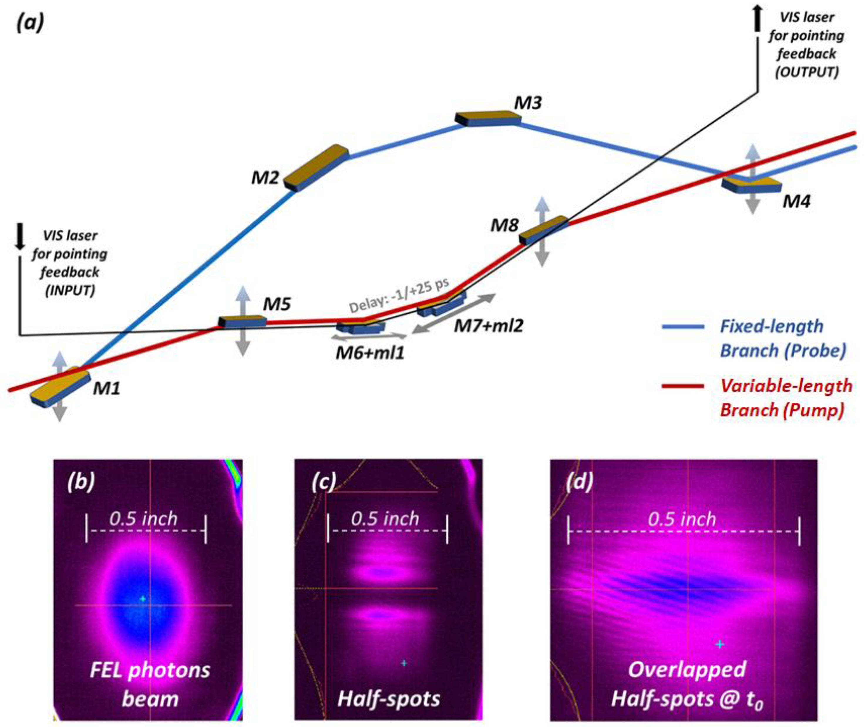
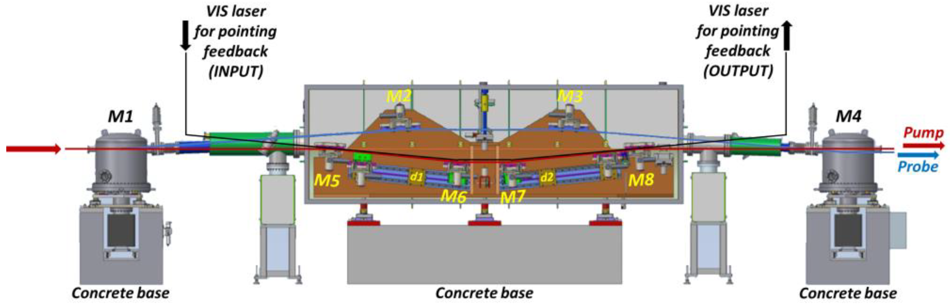
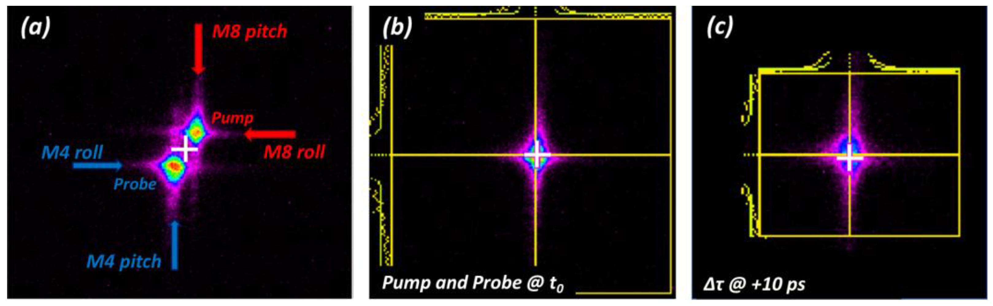
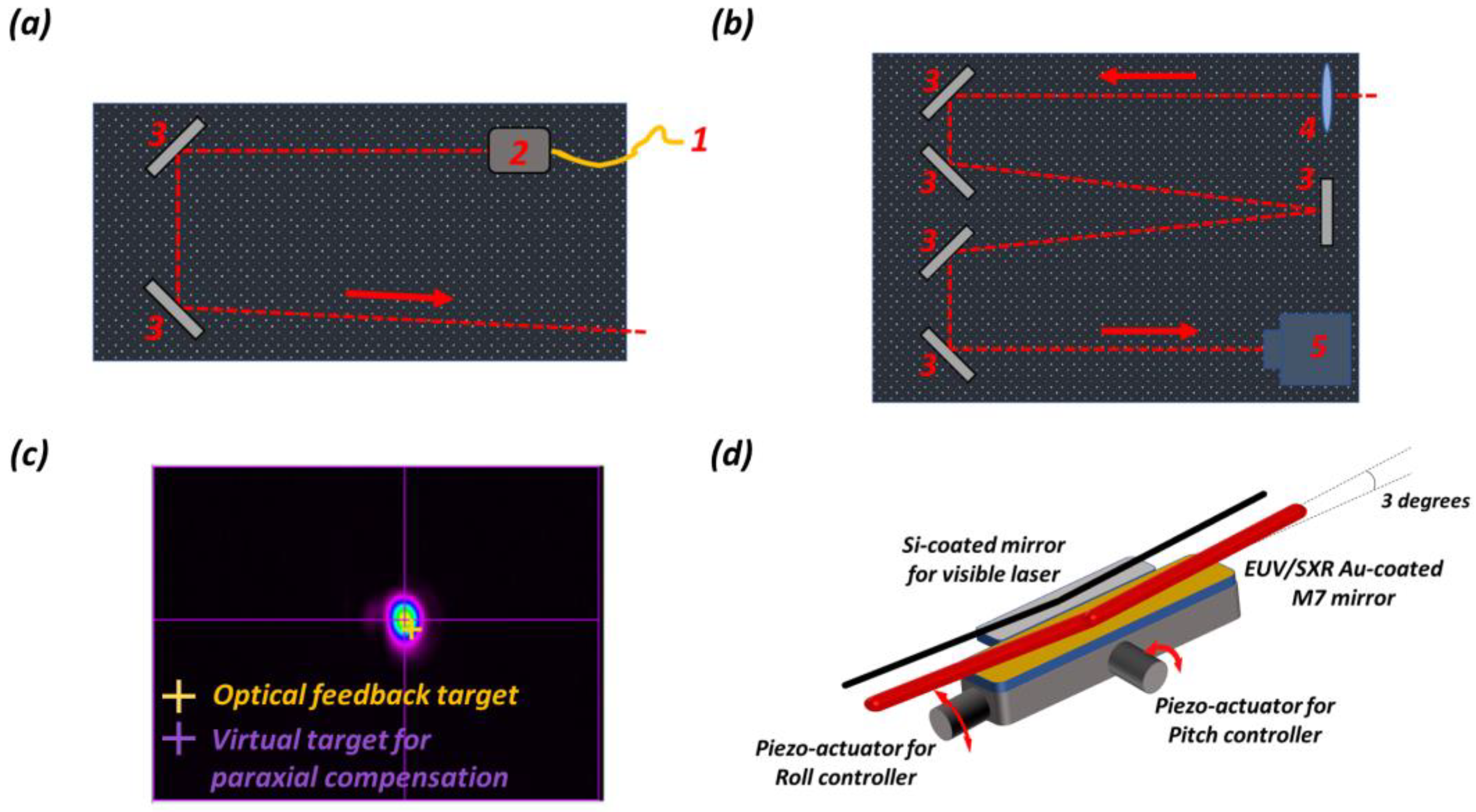
3.1. Alignment
3.2. Pointing Instability and Feedback System
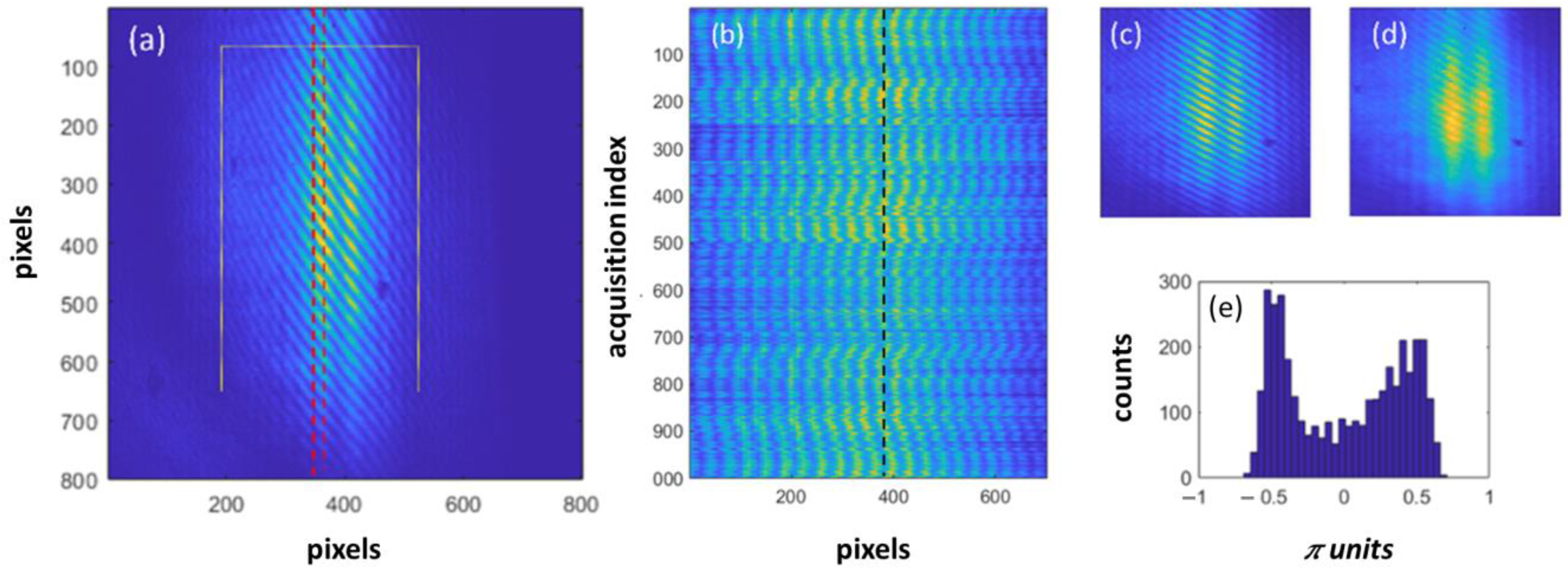
3.3. Fringe Stability
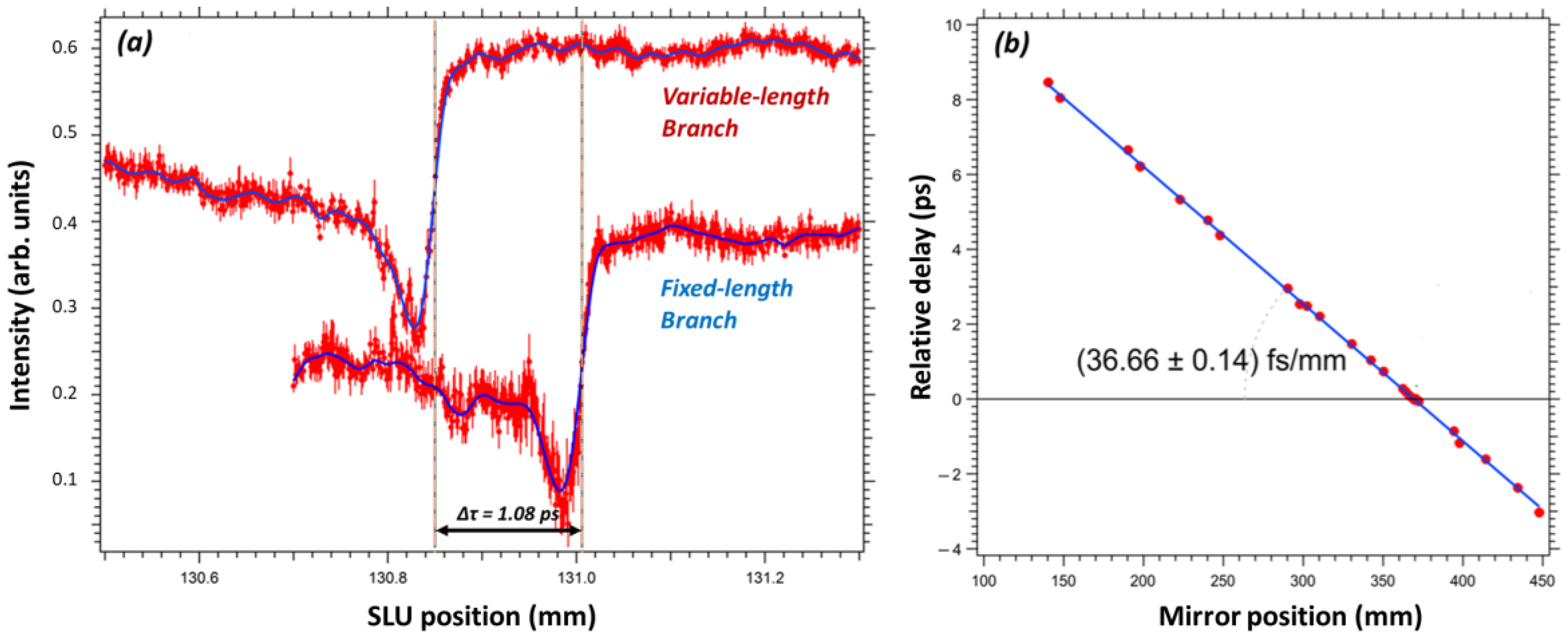
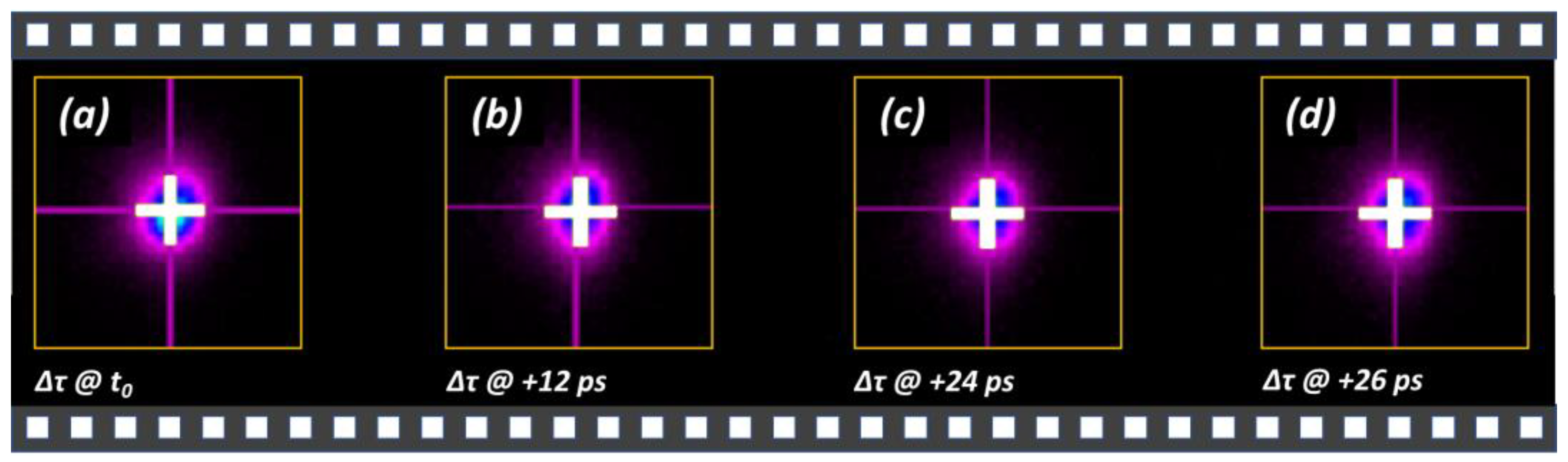
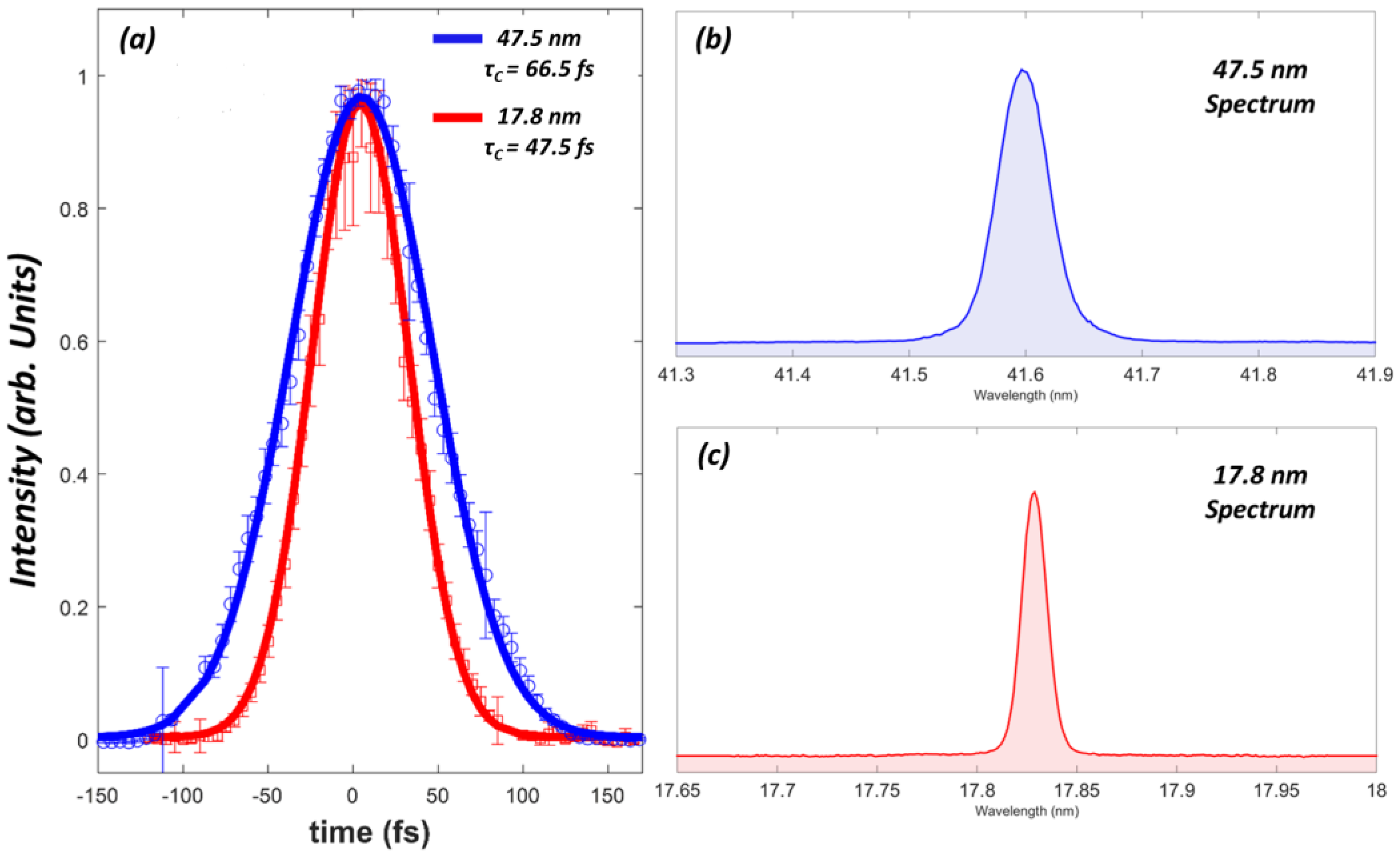
3.4. The Time-Dependent Amplitude-Autocorrelation
4. Conclusions
Author Contributions
Funding
Institutional Review Board Statement
Informed Consent Statement
Data Availability Statement
Acknowledgments
Conflicts of Interest
References
- Pellegrini, C.; Marinelli, A.; Reiche, S. The physics of x-ray free electron lasers. Rev. Mod. Phys. 2016, 88, 015006. [Google Scholar] [CrossRef]
- Bostedt, C.; Boutet, S.; Fritz, D.M.; Huang, Z.; Lee, H.J.; Lemke, H.T.; Robert, A.; Schlotter, W.F.; Turner, J.J.; Williams, G.J. Linac Coherent Light Source: The first five years. Rev. Mod. Phys. 2016, 88, 015007. [Google Scholar] [CrossRef] [Green Version]
- Schreiber, S. First Lasing at 32 nm of the VUV-FEL at DESY. In Proceedings of the 27th International Free Electron Laser Conference (FEL 2005), Stanford, CA, USA, 21–26 August 2005; pp. 12–18. [Google Scholar]
- Chalupský, J.; Krzywinski, J.; Juha, L.; Hájková, V.; Cihelka, J.; Burian, T.; Vyšín, L.; Gaudin, J.; Gleeson, A.; Jurek, M.; et al. Spot size characterization of focused non-Gaussian X-ray laser beams. Opt. Express 2010, 18, 27836. [Google Scholar] [CrossRef] [PubMed]
- Grguraš, I.; Maier, A.R.; Behrens, C.; Mazza, T.; Kelly, T.J.; Radcliffe, P.; Düsterer, S.; Kazansky, A.K.; Kabachnik, N.M.; Tschentscher, T.; et al. Ultrafast X-ray pulse characterization at free-electron lasers. Nat. Photonics 2012, 6, 852. [Google Scholar] [CrossRef]
- Schulz, S.; Grguras, I.; Behrens, C.; Bromberger, H.; Costello, J.T.; Czwalinna, M.K.; Felber, M.; Hoffmann, M.C.; Ilchen, M.; Liu, H.Y.; et al. Femtosecond all-optical synchronization of an X-ray free-electron laser. Nat. Commun. 2015, 6, 5938. [Google Scholar] [CrossRef] [Green Version]
- Allaria, E.; Appio, R.; Badano, L.; Barletta, W.A.; Bassanese, S.; Biedron, S.G.; Borga, A.; Busetto, E.; Castronovo, D.; Cinquegrana, P.; et al. Highly coherent and stable pulses from the FERMI seeded free-electron laser in the extreme ultraviolet. Nat. Photonics 2012, 6, 699–704. [Google Scholar] [CrossRef]
- Allaria, E.M.; Diviacco, B.; Callegari, C.; Finetti, P.; Mahieu, B.; Viefhaus, J.; Zangrando, M.; De Ninno, G.; Lambert, G.; Ferrari, E.; et al. Control of the Polarization of a Vacuum-Ultraviolet, High-Gain, Free-Electron Laser. Phys. Rev. X 2014, 4, 41040. [Google Scholar] [CrossRef] [Green Version]
- Allaria, E.M.; Battistoni, A.; Bencivenga, F.; Borghes, R.; Callegari, C.; Capotondi, F.; Castronovo, D.; Cinquegrana, P.; Cocco, D.; Coreno, M.; et al. Tunability experiments at the FERMI@Elettra free-electron laser. New J. Phys. 2012, 14, 113009. [Google Scholar] [CrossRef]
- Dell’Angela, M.; Hieke, F.; Malvestuto, M.; Sturari, L.; Bajt, S.; Kozhevnikov, I.V.; Ratanapreechachai, J.; Caretta, A.; Casarin, B.; Glerean, F.; et al. Extreme ultraviolet resonant inelastic X-ray scattering (RIXS) at a seeded free-electron laser. Sci. Rep. 2016, 6, 38796. [Google Scholar] [CrossRef] [Green Version]
- Prince, K.C.; Allaria, E.; Callegari, C.; Cucini, R.; de Ninno, G.; di Mitri, S.; Diviacco, B.; Ferrari, E.; Finetti, P.; Gauthier, D.; et al. Coherent control with a short-wavelength free-electron laser. Nat. Photonics 2016, 10, 176–179. [Google Scholar] [CrossRef]
- Principi, E.; Krylow, S.; Garcia, M.E.; Simoncig, A.; Foglia, L.; Mincigrucci, R.; Kurdi, G.; Gessini, A.; Bencivenga, F.; Giglia, A.; et al. Atomic and electronic structure of solid-density liquid carbon. Phys. Rev. Lett. 2020, 125, 155703. [Google Scholar] [CrossRef] [PubMed]
- Lu, W.; Friedrich, B.; Noll, T.; Zhou, K.; Hallmann, J.; Ansaldi, G.; Roth, T.; Serkez, S.; Geloni, G.; Madsen, A.; et al. Development of a hard X-ray split-and-delay line and performance simulations for two-color pump-probe experiments at the European XFEL. Rev. Sci. Instrum. 2018, 89, 063121. [Google Scholar] [CrossRef] [PubMed]
- Roseker, W.; Hruszkewycz, S.O.; Lehmkühler, F.; Walther, M.; Schulte-Schrepping, H.; Lee, S.; Osaka, T.; Strüder, L.; Hartmann, R.; Sikorski, M.; et al. Towards ultrafast dynamics with split-pulse X-ray photon correlation spectroscopy at free electron laser sources. Nat. Commun. 2018, 9, 1704. [Google Scholar] [CrossRef] [PubMed]
- Mandal, A.; Sidhu, M.S.; Rost, J.M.; Pfeifer, T.; Singh, K.P. Attosecond delay lines: Design, characterization and applications. Eur. Phys. J. Spec. Top. 2021, 230, 4195. [Google Scholar] [CrossRef]
- Zangrando, M.; Cudin, I.; Fava, C.; Gerusina, S.; Gobessi, R.; Godnig, R.; Rumiz, L.; Svetina, C.; Parmigiani, F.; Cocco, D. First Results from the Commissioning of the FERMI@Elettra Free Electron Laser by Means of the Photon Analysis Delivery and Reduction System (PADReS). Proc. SPIE 2011, 8078, 80780I. [Google Scholar]
- Allaria, E.; Bencivenga, F.; Borghes, R.; Capotondi, F.; Castronovo, D.; Charalambous, P.; Cinquegrana, P.; Danailov, M.B.; de Ninno, G.; Demidovich, A.; et al. Two-colour pump–probe experiments with a twin-pulse-seed extreme ultraviolet free-electron laser. Nat. Commun. 2013, 4, 2476. [Google Scholar] [CrossRef]
- Danailov, M.B.; Bencivenga, F.; Capotondi, F.; Casolari, F.; Cinquegrana, P.; Demidovich, A.; Giangrisostomi, E.; Kiskinova, M.P.; Kurdi, G.; Manfredda, M.; et al. Towards jitter-free pump-probe measurements at seeded free electron laser facilities. Opt. Express 2014, 22, 12869–12879. [Google Scholar] [CrossRef]
- Weaver, J.H.; Krafka, C.; Lynch, D.W.; Koch, E.E. Physics Data: Optical Properties of Metals, 18; Fach-Iformation Zentrum: Karlsruhe, Germany, 1981. [Google Scholar]
- Center for X-Rays Optics Database. Available online: https://henke.lbl.gov/optical_constants/ (accessed on 31 December 2021).
- Raimondi, L.; Svetina, C.; Mahne, N.; Cocco, D.; Abrami, A.; de Marco, M.; Fava, C.; Gerusina, S.; Gobessi, R.; Capotondi, F.; et al. Microfocusing of the FERMI@Elettra FEL beam with a K-B active optics system: Spot size predictions by application of the WISE code. Nucl. Instrum. Meth. A 2013, 710, 131–138. [Google Scholar] [CrossRef]
- Raimondi, L.; Svetina, C.; Mahne, N.; Cocco, D.; Capotondi, F.; Pedersoli, E.; Kiskinova, M.; Keitel, B.; Brenner, G.; Ploenjes, E.; et al. K-B bendable system optimization at FERMI@Elettra FEL: Impact of different spatial wavelengths on the spot size. Proc. SPIE 2013, 8848, 63–70. [Google Scholar]
- Manfredda, M.; Fava, C.; Gobessi, S.G.R.; Mahne, N.; Raimondi, L.; Simoncig, A.; Zangrando, M. The evolution of KAOS, a multipurpose active optics system for EUV/Soft X-rays. Syn. Rad. News 2022. accepted. [Google Scholar]
- Menk, R.H.; Arfelli, F.; Cautero, M.; Cautero, G.; di Fraia, M.; Coreno, M.; Galdenzi, F.; Tutsch, W. On the possibility to utilize a PCO Edge 4.2 bi scientific CMOS imager for extended ultra violet and soft X-ray photon detection. JINST 2022, 17, C01058. [Google Scholar] [CrossRef]
- Capotondi, F.; Foglia, L.; Kiskinova, M.P.; Masciovecchio, C.; Mincigrucci, R.; Naumenko, D.; Pedersoli, E.; Simoncig, A.; Bencivenga, F. Characterization of ultrafast free-electron laser pulses using extreme-ultraviolet transient gratings. J. Synchrotron Rad. 2018, 25, 32. [Google Scholar] [CrossRef] [PubMed] [Green Version]
- Hartmann, N.; Hartmann, G.; Heider, R.; Wagner, M.S.; Ilchen, M.; Buck, J.; Lindahl, A.O.; Benko, C.; Grünert, J.; Krzywinski, J.; et al. Attosecond time–energy structure of X-ray free-electron laser pulses. Nat. Photonics 2018, 12, 215. [Google Scholar] [CrossRef]
- Ackermann, W.A.; Asova, G.; Ayvazyan, V.; Azima, A.; Baboi, N.; Bähr, J.; Balandin, V.; Beutner, B.; Brandt, A.; Bolzmann, A.; et al. Operation of a free-electron laser from the extreme ultraviolet to the water window. Nat. Photonics 2007, 1, 336–342. [Google Scholar] [CrossRef]


Publisher’s Note: MDPI stays neutral with regard to jurisdictional claims in published maps and institutional affiliations. |
© 2022 by the authors. Licensee MDPI, Basel, Switzerland. This article is an open access article distributed under the terms and conditions of the Creative Commons Attribution (CC BY) license (https://creativecommons.org/licenses/by/4.0/).
Share and Cite
Simoncig, A.; Manfredda, M.; Gaio, G.; Mahne, N.; Raimondi, L.; Fava, C.; Gerusina, S.; Gobessi, R.; Abrami, A.; Capotondi, F.; et al. AC/DC: The FERMI FEL Split and Delay Optical Device for Ultrafast X-ray Science. Photonics 2022, 9, 314. https://doi.org/10.3390/photonics9050314
Simoncig A, Manfredda M, Gaio G, Mahne N, Raimondi L, Fava C, Gerusina S, Gobessi R, Abrami A, Capotondi F, et al. AC/DC: The FERMI FEL Split and Delay Optical Device for Ultrafast X-ray Science. Photonics. 2022; 9(5):314. https://doi.org/10.3390/photonics9050314
Chicago/Turabian StyleSimoncig, Alberto, Michele Manfredda, Giulio Gaio, Nicola Mahne, Lorenzo Raimondi, Claudio Fava, Simone Gerusina, Riccardo Gobessi, Alessandro Abrami, Flavio Capotondi, and et al. 2022. "AC/DC: The FERMI FEL Split and Delay Optical Device for Ultrafast X-ray Science" Photonics 9, no. 5: 314. https://doi.org/10.3390/photonics9050314