Article

Design and Optimization of Asymmetric Grating Assisted Slot Microring

1
School of Electronics and Information Engineering, Lanzhou Jiaotong University, Lanzhou 730070, China
2
Key Laboratory of Opto-Technology and Intelligent Control, Lanzhou Jiaotong University, Ministry of Education, Lanzhou 730070, China
*
Author to whom correspondence should be addressed.
Photonics 2022, 9(12), 988; https://doi.org/10.3390/photonics9120988
Submission received: 19 November 2022 / Revised: 9 December 2022 / Accepted: 12 December 2022 / Published: 15 December 2022
(This article belongs to the Special Issue Integrated Waveguide-Based Photonic Devices)

Abstract

:
In this paper, a slot microring with an asymmetric grating structure is proposed. Through the coupling between the grating and the slot microring, a high free spectral range or EIT-like effects with a high quality factor can be achieved in the same device. The grating is designed as an asymmetric structure to realize the modulation of the optical signal and the control of the resonance peak by changing the grid number, and the effect of different grating periods on the output spectrum is explored. The results show that changing the grating on slot sidewalls can increase or decrease the number of resonant peaks. By selecting a specific period of the gratings on both sides of the slot, the distance between adjacent resonance peaks can be increased to achieve modulation of the free spectral range. In this paper, depending on the grating period, we obtain a quality factor of 5016 and an FSR of 137 nm, or a quality factor of 10,730 and an FSR of 92 nm. The refractive index sensing simulation is carried out for one of the periods, which can achieve a sensitivity of 370 nm/RIU. Therefore, the proposed new structure has certain advantages in different sensing applications.

1. Introduction

Silicon-on-insulator (SOI)-based photonic devices have become the focus of many researchers due to their low cost, high compatibility and excellent sensing performance. In particular, the high integration and high quality factor (Q) of microring resonators make them an important part of integrated photonic devices. By measuring the spectral shift caused by different parameters, such as refractive index, temperature and pressure [1,2], the sensitivity of the device regarding this parameter can be obtained, and the sensing function can be realized. At present, the optical sensor devices based on microring resonators have been extensively investigated. Different structures or new materials have been adopted in microring devices, including cascaded microring resonator [3,4], Fabry–Perot cavity composite racetracks [5], cascaded SLR Fabry–Perot cavities on both sides [6], concentric triple microring [7], three-ring structure cascading [8], the use of chalcogenide glasses [9] and lithium tantalate materials [10], or achieving different output effects, such as flat bandwidth [11], high ER [12,13] and small linewidth [14,15,16], by which a certain device performance is improved, but there is an incompatibility between sensitivity and the measurement range.
Considering that the grating is a special structure, which can better realize the interaction between light and matter, the grating can therefore be coupled with other structures to obtain excellent transmission effects [17,18,19]. In recent years, many grating–microring composite structures can be directly used as sensing and detection to obtain high Q value or detection sensitivity [20,21,22], such as cantilever-based fiber Bragg grating sensor [23], microring coupled phase-shift Bragg grating structures [24] and functionalized etched fiber Bragg grating sensors [25]. In addition to gratings, there are also structures that couple photonic crystals with microrings [26,27], which operate based on the slow light effect and achieve extremely high quality factors, but the measurement range is limited due to low FSR. The above solutions only focus on improving a certain parameter of the sensing characteristics. We also proposed a high-sensitivity double-slot microring resonator structure with unlimited FSR in our previous work [28], but its Q value is relatively low, and the structure is a bit complicated. Therefore, how to improve the comprehensive performance has been an important issue in the SOI-based refractive index sensor while ensuring a small volume and a simple structure.
In this paper, a new type of microring structure realized by asymmetric sidewall modulation grating of silicon-based waveguide (ASGMRR) is proposed. The theoretical analysis is carried out first, and then, the scanning optimization is carried out according to the transmission result. The transmission characteristics will also change according to the grating period. Finally, the grating period with larger FSR is selected, and its sensing performance is evaluated by detecting the aqueous solution with the refractive index of 1.3332 to 1.3382. ASGMRR can reflect multiple wavelengths at the same time without using cascade gratings in a limited space, which increases the FSR and reduces the complexity of the device. The device has a high Q value and sensitivity, which is beneficial for refractive index sensing.

2. Structure Design and Theoretical Analysis

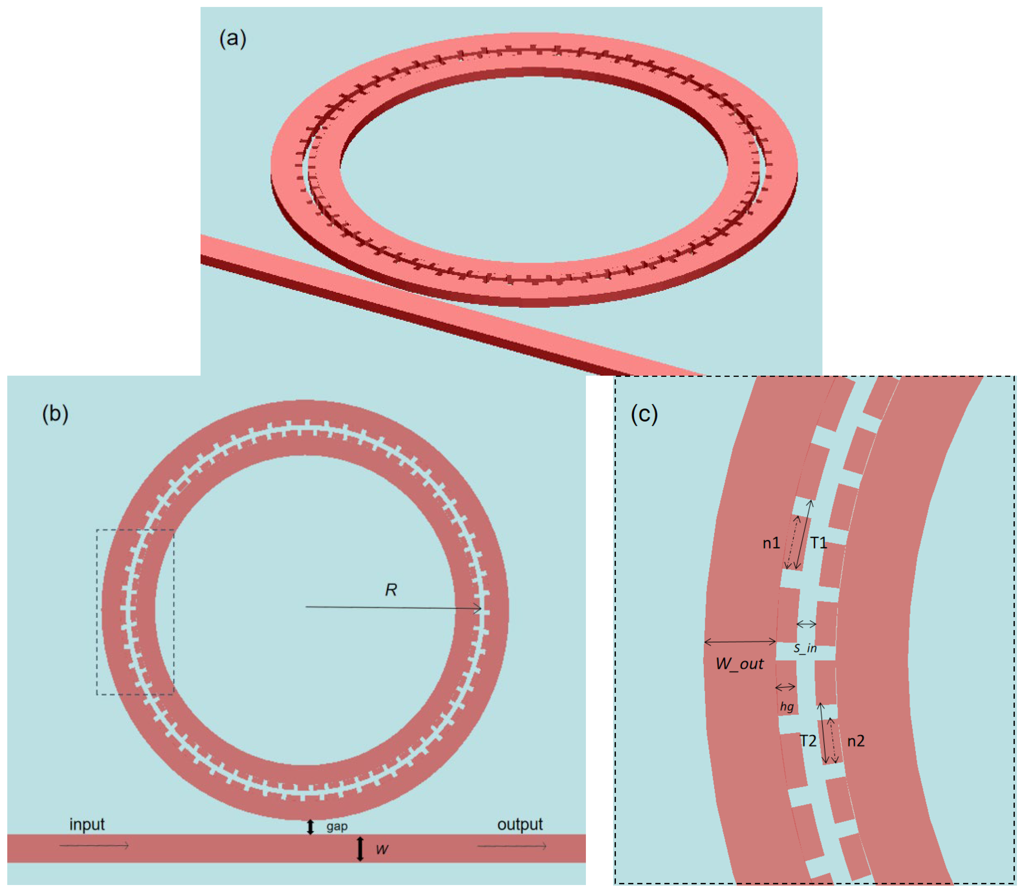
2.1. Structure Design

As shown in Figure 1a, ASGMRR is designed on an SOI platform with 2 μm SiO2 substrate, which consists of a straight busbar waveguide and a slot microring, and the silicon layer height is 220 nm. Two grating structures with different periods are embedded in the inner wall of the slot, which expands the interaction area between the microring and the external environment while reflecting light of different wavelengths, thereby obtaining different FSRs and sensitivities. As shown in Figure 1b,c, the radius from the center of the microring to the center of the slot is defined as R, and its size is 3.5 μm. Define the distance between the microring and the busbar waveguide as a gap, and its size is 0.2 μm. Define the thickness of the busbar waveguide as W, and its size is 4 μm. Define the microring thickness as W_out, and its size is 2.2 μm. Define the slot width as S_in, and its size is 0.04 μm. Define the grating etching depth as hg, and its size is 0.028 μm. Define the duty cycle of the outer and inner gratings as n, and their sizes are both 0.9.
A TE-like mode source with adjustable wavelength is added to one end of the busbar waveguide, and evanescent waves will be generated around the busbar waveguide during transmission. The light with a wavelength that satisfies the resonance equation of the microring will be coupled into the microring. The grating will reflect light at some wavelengths, and the reflected light interacts with the forward transmitted light, which can suppress part of the resonant light and can also form an EIT-like effect. In the absorption spectrum of the EIT-like effect, there is a very broad absorption peak, and there is a relatively narrow depression in the middle of the absorption peak. The resonance frequency is the lowest point of the depression, and the absorption is extremely low, that is, the substance is transparent to the detection light. If multiple wavelengths need to be reflected at the same time, gratings with different periods are usually cascaded, which will cause the device to take up too much space. In our structure, two gratings with different periods can be added in the same slot to achieve the same function as the cascaded gratings and greatly reduce the occupied space. Waveform modulation of the output spectrum can be achieved by changing the grating period on both sides of the slot. The EIT-like line type can be achieved at different wavelengths, or the FSR can be enlarged by suppressing part of the resonance peaks. In this paper, although we only consider the spectral changes in the wavelength range from 1550 nm to 1700 nm, by changing the parameters of the grating, spectral modulation can also be performed over a wider range to detect liquids of different compositions and refractive indices.

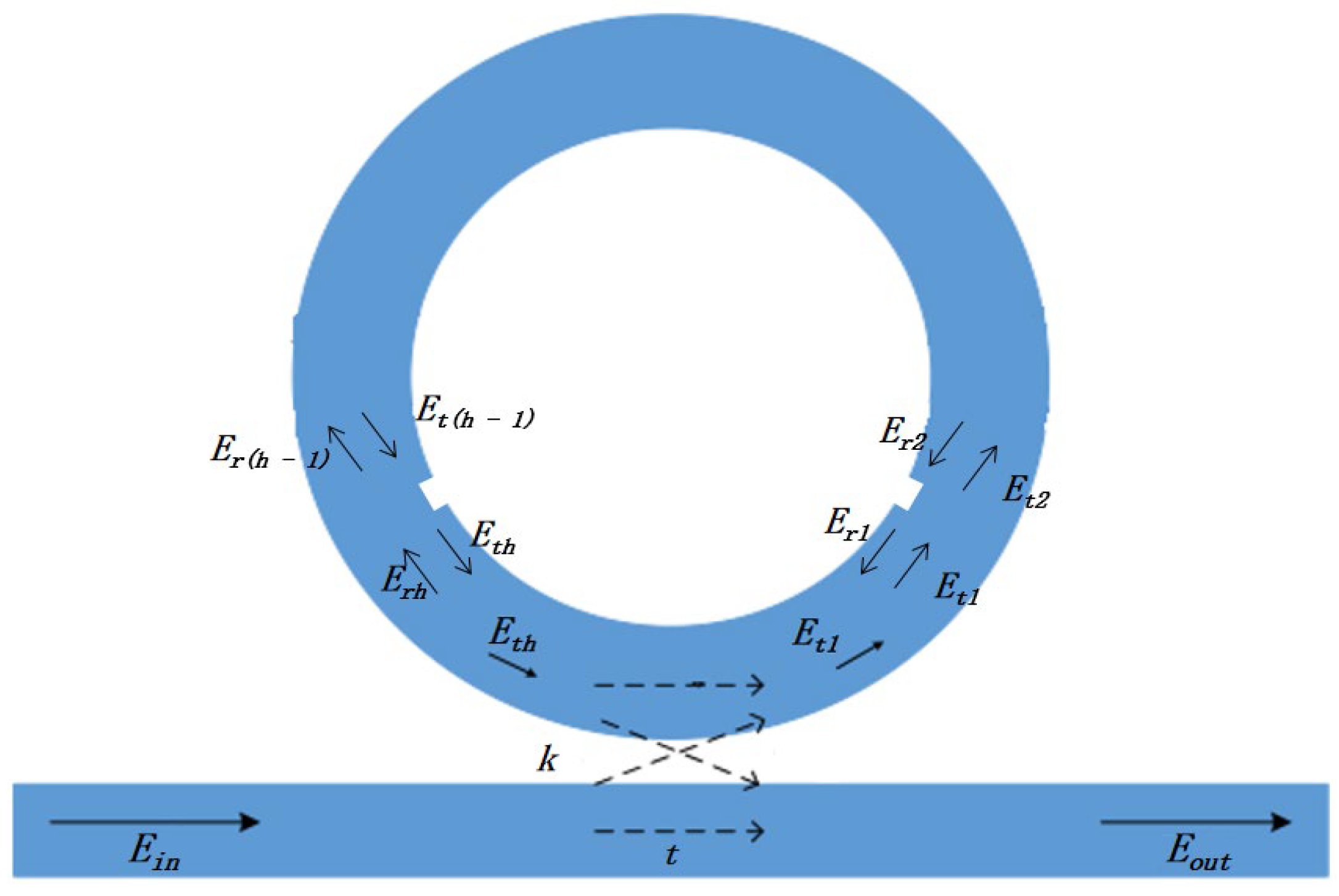
2.2. Theoretical Analysis

The coupling coefficient of the grating can be defined as
κ = κ 0 2 n e f f Δ n 2 ( x , y ) E 2 ( x , y ) d x d y E 2 ( x , y ) d x d y
where ∆n is the amount of change in the refractive index of the grating with distance. From the results of subsequent simulation, this formula is still applicable to gratings with different periods. We will analyze its theory in future studies because theoretical studies on asymmetric grating structures are valuable.
The change of the coupling rate will cause the change of the reflection bandwidth of the grating (∆λ), which is another important parameter in the grating structure, and ∆λ can be written as
Δ λ = λ B 2 π n g κ 2 + ( π / L ) 2
where λB is the Bragg wavelength, ng is the group refractive index, L is the total length of the grating, and k is the coupling rate of the grating structure. By setting the parameters, such as the length of the grating and the coupling rate, the modulation of the reflection bandwidth of the grating can be realized, and the expansion of the FSR can be realized.
As shown in Figure 2, a beam of light enters the busbar waveguide; when it passes through the coupling area with the microring, some resonant light will be coupled into the microring, which is determined by the transmission coefficient t and the coupling coefficient k. Assuming negligible losses and setting the number of grating teeth to h, the transmission of resonant light in the microring can be modeled as
( E o u t E t 1 ) = ( t i k i k t ) ( E i n E t h )
Equation (3) represents the transmission between the busbar waveguide and the microring, where Eout and Ein are the intensities of the output light and input light, respectively; Et1 is the transmitted light intensity when the resonant light passes through the first grating tooth; and Eth is the resonant light transmission intensity after passing through the last grating tooth.
Considering only the transmission of light in the first and second grating teeth, the transmission matrix can be written as
( E t 1 E r 2 ) = ( s r r s ) ( E t 2 E r 1 )
In Equation (4), s and r represent the transmission coefficient and reflection coefficient, respectively; Et2 is the transmitted light intensity of the second grating tooth; Er1 and Er2 are the reflected light intensity of the first grating tooth and the second grating tooth, respectively.
Since the number of grating teeth is large, and the distance is short, the attenuation can be ignored, so the matrix of a single grating tooth can be applied to the entire grating, as shown in Equation (5):
( E t 1 E r h ) = ( S R R S ) ( E t h E r 1 )
where Erh represents the reflection of the last grating tooth light intensity; S and R represent the matrix parameters after analyzing all grating teeth in pairs.
Combining Equations (3) and (5), the relationship between input light and output light can be obtained:
( E o u t E r 1 ) = ( u v x y ) ( E i n E r h )
In Equation (6), u, v, x and y are determined by physical parameters, such as effective refractive index, the angle between adjacent grating teeth and microring center, the number of grating teeth and duty cycle, and these parameters determine the final transmission effect. The above analysis only applies to the approximate relationship between the input light and the output light in a set of gratings. In our structure, there are two sets of gratings with different periods inside and outside, which can be analyzed separately, and then, the output results can be superimposed [29].
In particular, the position of the output resonance peak can be determined by
π R n e f f = m f n 2 e f f 1 + ( 1 n ) n 2 e f f 2 Λ
where Λ is the gratings period; neff1 and neff2 represent the effective refractive index of the concave and convex parts of the gratings, respectively; and n is the duty cycle of the gratings.
The ideal transmission result of ASGMRR is shown in Figure 3b. The black line in the figure represents the transmission spectrum under ideal conditions, while the red line represents the filtering effect of ASGMRR on the wavelength. Compared with the transmission spectrum of the grating-free microring structure in Figure 3a, ASGMRR selectively filters out part of the resonant light and makes the FSR extension three times the original, which provides a new idea for obtaining high sensitivity and measurement range at the same time.

3. Structural Optimization

ASGMRR was modeled and the transmission spectrum was simulated by Lumerical MODE Solution, an FDTD software of Lumerical Inc. The version of the software is 2020 R2.
The cross-section of light traveling in the microring slot is shown in Figure 4. It can be seen that the slot structure can better confine the light to the central area, reduce the energy scattered into the air and provide lower light dissipation. When performing refractive index sensing, the detection object will be completely filled in the slot structure and fully contacted with the structure to enhance the influence of the refractive index of the object to be detected on the light transmission in the slot, thereby greatly improving the sensitivity of the device.
The top view of the mode field when light is transmitted in the device is shown in Figure 5. It shows the energy field distribution in ASGMRR. When the light is transmitted in the slot, part of the light will be reflected by the gratings on both sides of the slot. The reflected light will interact with the forward propagating light, thereby suppressing the light at this resonant wavelength. When light travels in a waveguide, some of the light is scattered into the air. If the slot structure is used, a small part of the light will be scattered into the waveguide and then scattered into the air, which will cause less loss. The asymmetrical grating in the slot will cause a certain propagation loss, and its magnitude is linear with the grating length, about 30 dB/m, which can be ignored in ASGMRR. The bending of the microring will also cause a certain loss. Due to the high refractive index contrast of the SOI waveguide, the bending loss of the microring resonator can be ignored when R > 3 μm [30], but too large radius will make the optical path longer and the scattering loss greater. Methods such as thermal oxidation and annealing can be used to reduce sidewall roughness during actual device fabrication. In addition, it should be noted that when the light enters the ASGMRR, there will be an insertion loss of about 0.5 dB, and when the light is coupled from the busbar waveguide into the microring, there will also be some loss. Selecting the appropriate coupling spacing and radius can better confine the light in the slot and reduce the transmission loss.

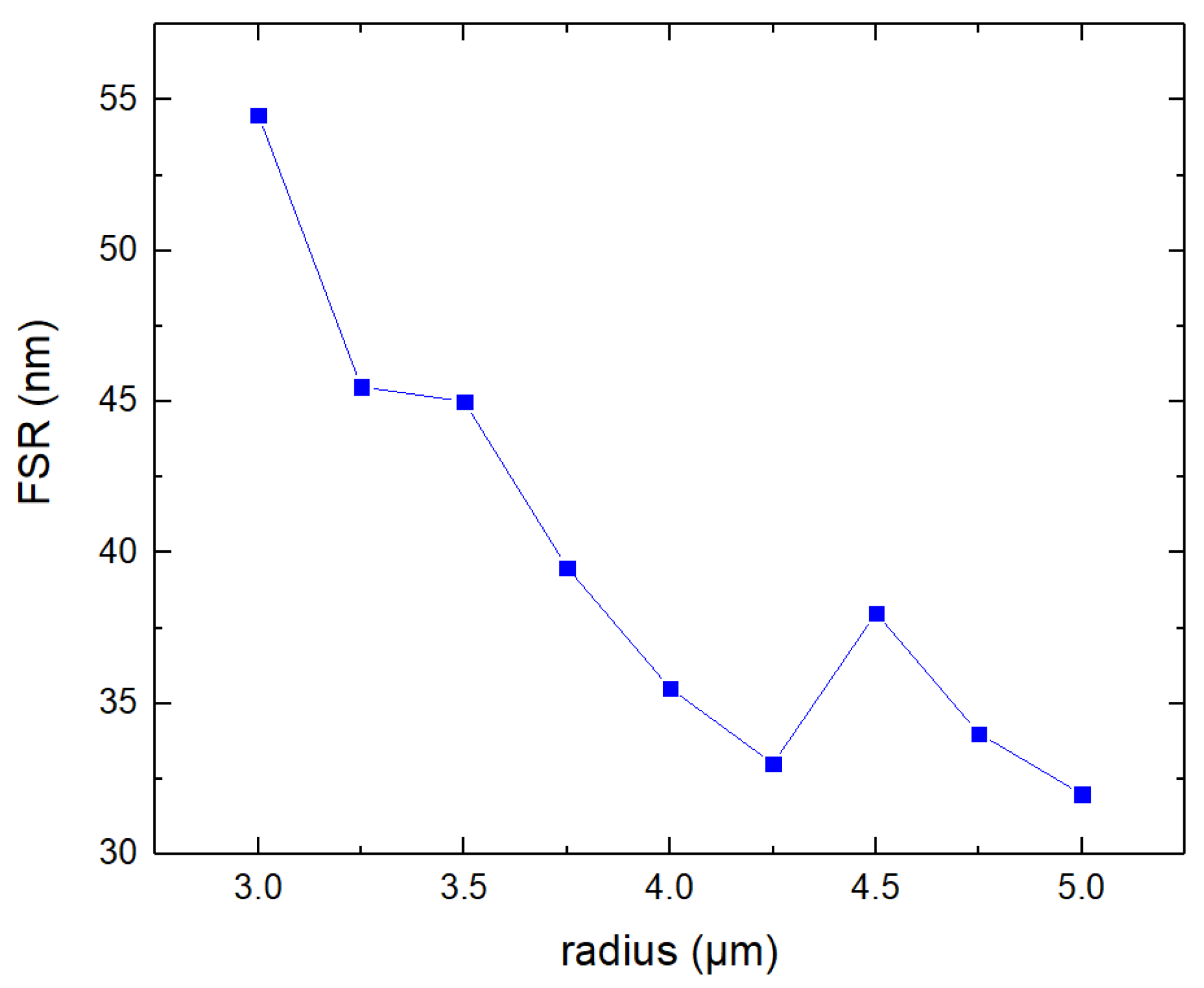
3.1. Microring Radius
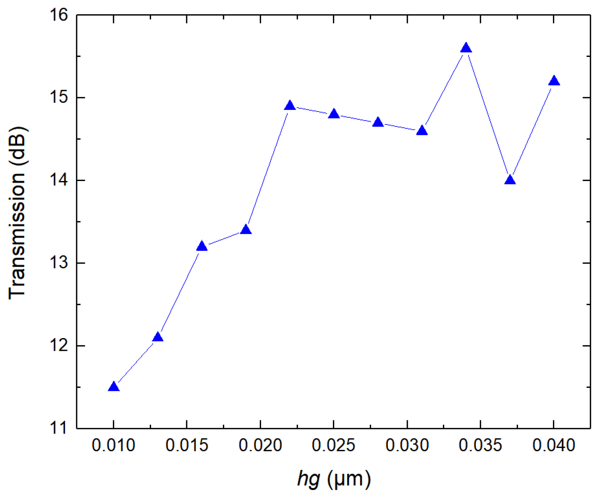
The change of the microring radius will cause the optical path length to change, and the grating length L will also increase with the increase in the microring radius, which will ultimately affect the reflection bandwidth of the output spectrum, and the FSR of adjacent resonance peaks will change. The FSR is a parameter used in microring resonators to define the wavelength difference between two adjacent resonance peaks in a continuous spectrum. The FSR meets the following conditions:
FSR = λ 2 2 π n g R
The dependence of FSR on the radius is shown in Figure 6. It can be seen that the FSR decreases with the increase in the radius. The variation trend of FSR changes when the radius is 4.5 μm, which may be caused by the interaction of several possible reasons not considered here, such as the change of the coupling state between the grating and the microring due to the change of the radius of the microring. In the subsequent optimization, the Q value and extinction ratio are optimized, and by changing the parameters of the grating, some resonance peaks are suppressed to achieve the purpose of increasing the FSR.

3.2. Grating Depth

We consider modulations that include gratings along the two sidewalls. The output spectrum varies with the grating etch depth hg. The range of hg is selected from 0.01 μm to 0.04 μm, and the change of output light transmittance with hg is shown in Figure 7. When hg is higher than 0.02 μm, higher transmittance can be obtained, but the suppression of secondary resonance peaks is weakened when hg exceeds 0.03 μm. This is because the reflection of the resonant light in the grating is weakened with the increase in the grating depth when the width of the slot, excluding the grating, remains unchanged, and the selection effect of the grating on specific wavelengths will be reduced. When the grating depth increases to more than 0.02 μm, the increase trend of the transmittance of the output light slows down because the ability of the grating to reflect light reaches the upper limit, and the benefit of increasing the grating depth to the transmittance decreases. When the grating depth exceeds 0.03 μm, the reason for the fluctuation of the transmittance may be that the increase in the grating depth leads to the change of the overall radius of the microring, which changes the selectivity of the resonant light and changes the intensity of the resonant light. When we take the grating depth as 0.028 μm, the influence on the output is small within a certain range of depth variation, so there is a manufacturing tolerance. Therefore, the grating depth of 0.028 μm is a suitable value, and the output light intensity is 14.7 dB at this time. The runway MRR based on gratings has been proposed and fabricated [19], whose grating depth is only 15 nm. Therefore, our device with 28 nm grating depth can be completely realized under the current processing and preparation conditions. In addition, an excessively wide slot also reduces the output light intensity, which may be due to the fact that the excessive slot width will reduce the coupling coefficient, thereby weakening reflections at the interface between the waveguide slot and the grating.

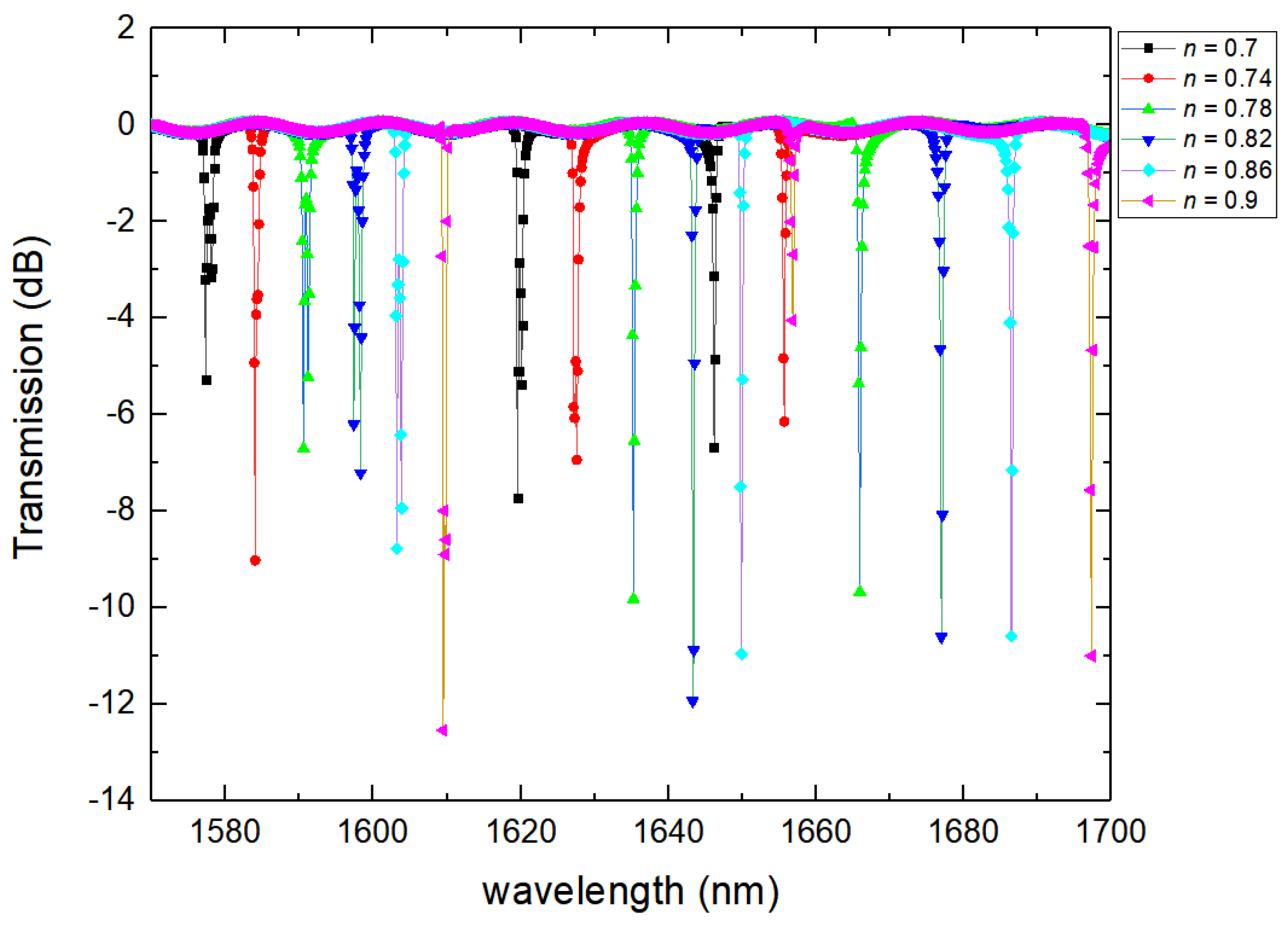
3.3. Grating Duty Cycle

The proportion of silicon material in a grating grid is the duty cycle of the grating, which is an important factor affecting the position and intensity of the resonance wavelength of the output spectrum. If the duty cycle is too small, the resonant light will be cut off, and if the duty cycle is too large, the selection effect on the resonant light will be weakened. Therefore, the duty cycle is usually between 0.7 and 0.9. In all our subsequent simulations, the wavelength resolution of the output spectrogram obtained by the monitor is 20 points/nm. Figure 8 shows the influence of different duty cycles on the output spectra. As the duty cycle changes from 0.7 to 0.9, the resonance wavelength gradually undergoes a red shift, and the intensity gradually increases. When the duty cycle of the grating is varied in the range of 0.82 to 0.9, its resonant peak intensity is slightly affected, so there is a large tolerance for the insertion loss of the grating in the manufacturing. This somewhat reduces the effect of changes in grating parameters caused by stitching errors made by EBL on the results. The smaller the duty cycle is, the more light is coupled into the grating, and the optical path will also increase, which is equivalent to increasing the radius of the microring, resulting in an increase in the resonance wavelength and loss. As can be seen from the figure, when the duty cycle is 0.9, the suppression of the secondary resonance peak is the strongest, and the intensity of the main resonance peak is higher.

3.4. Grid Number/Period

We first simulate the transmission characteristics with only single-sided grating, and the length—that is, the period—is set according to the number of gratings in one cycle. Figure 9 shows the transmission characteristics when the number of inner and outer grating cells is 50, respectively. It can be seen from Figure 9 that the coupling of the microring and the grating leads to changes in the ER of the resonance peaks at different wavelengths, and there are splits at some of the peaks. Different position of the grating will also cause the resonance peak to change.
The Q factor is determined by the slope of the envelope at the resonant frequency, which is given by Equation (9):
Q = 2 π f R log 10 ( e ) 2 m
where fR is the resonant frequency of the mode, and m is the slope at the resonant frequency. After calculation, the Q values of the output spectra of the structures including only the inner wall grating and only the outer wall grating are 6461 and 6905, respectively, and their FSRs are only 47 nm.
Then, gratings are added to both sidewalls of the slot at the same time, allowing the period of each sidewall to vary independently. Theoretically, the spectral properties of multiple gratings can be considered as the superposition of spectral properties of more than two basic gratings [29]. Only modulations along the two sidewalls of the microring are included in our proposed structure. The output spectra under different grating periods on both sides of the slot are shown in Figure 10. It can be seen that the output spectrum has a small amplitude shift compared with the spectrum shown in Figure 9 with gratings on one side only. When the periods of the gratings on both sides of the slot are 70 and 50, respectively, the resonance peaks at 1598 nm and 1646 nm are suppressed because the gratings on both sides of the slot reflect the light at this wavelength at the same time, while at other resonant wavelengths, at least one side of the grating can pass the light at that wavelength. Therefore, in the proposed new structure, by selecting a suitable grating period, the FSR can reach 137 nm on the premise of ensuring a high Q value (5016).
When the grating periods of the inner and outer walls of the slot are 70 and 90, respectively, due to the selectivity of the grating, a transmission spectrum with EIT-like line type on both sides can be achieved, as shown in Figure 11. Although the FSR is 45 nm lower than the value obtained when the periods of the gratings on both sides of the slot are 70 and 50, respectively, a higher Q value of 10,730 can be obtained due to the EIT-like line type.
The Q factor and FSR in both cases are calculated by Equations (8) and (9). The simulation results by FDTD are roughly the same as the calculated results. In addition, according to the different periods on both sides of the inner wall of the slot, there can be more transmission spectra with different effects. At a certain value, sensing effects, such as higher transmittance and lower detection limit, can be obtained, and there are more different periods awaiting exploration. By setting different periods, we will achieve a more excellent transmission effect.

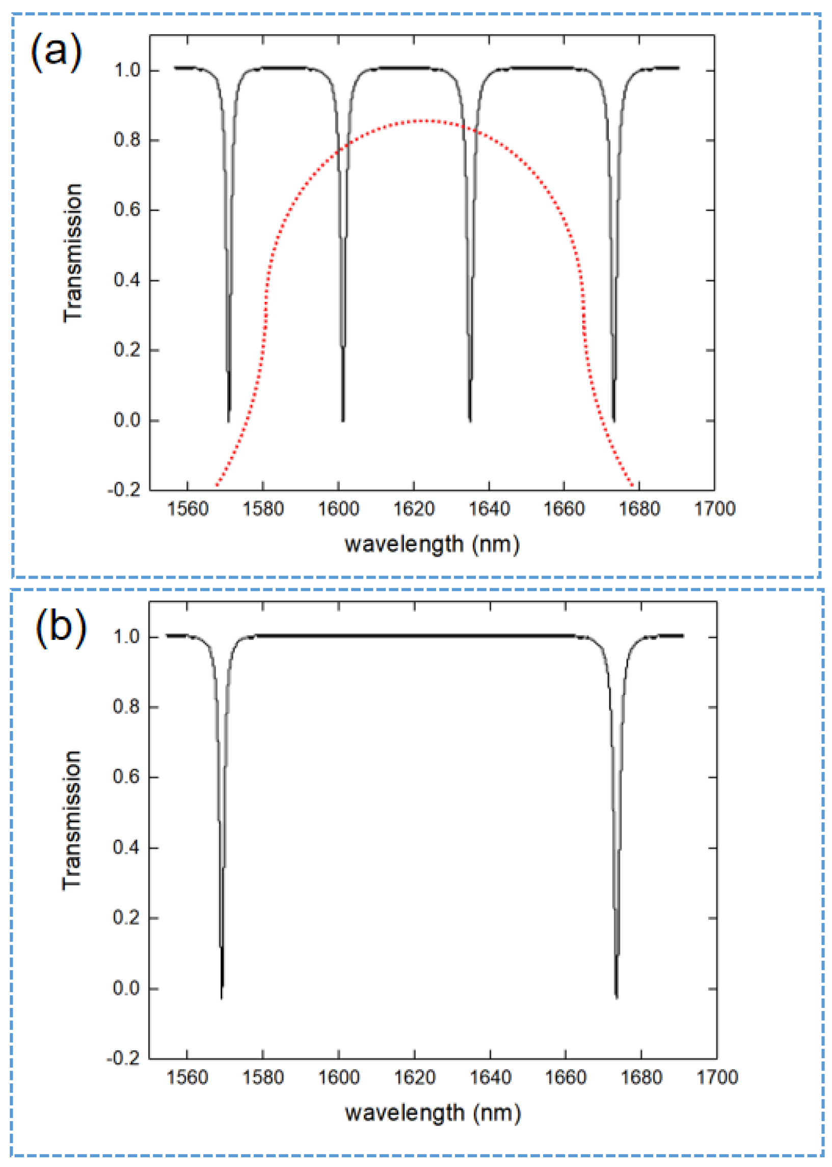
4. Results and Discussion

In this section, based on the optimal device parameters obtained above, the refractive index sensing performance of ASGMRR will be further studied; the transmission spectra under different ambient refractive indices are shown in Figure 12a. In the simulation, the ambient refractive index variation ranges from 1.3332 to 1.3382. As the concentration of the aqueous solution changes, the effective refractive index of the waveguide surface changes, and the output resonance wavelength shifts. The function curve between the ambient refractive index and resonant wavelength is shown in Figure 12b. The change of the output wavelength with the refractive index is a straight line, indicating that the sensing effect of the device is stable. As the refractive index difference between the analyte and ASGMRR gradually decreases, the coupling mode will also change accordingly, and its extinction ratio will fluctuate accordingly. In addition, according to the different refractive index of the object to be tested, the refractive index detection in different wavelength ranges can be realized by changing the structural parameters of ASGMRR. The light transmittance of the proposed structure varies greatly with the refractive index of the object to be tested, that is, the sensitivity is high. This is because the structure of the slot waveguide is adopted, the slot is filled with the liquid to be tested, and the liquid to be tested can fully contact the device, so that the effective refractive index of the surface of the device changes. The calculation formula of sensitivity S can be given by Equation (10):
S = Δ λ r e s Δ n
where ∆λres is the variation of resonant wavelength, and ∆n is the refractive index variation of the liquid.
Compared to the structures in other papers in Table 1, the performance parameters of our structure are relatively improved to some extent. In particular, the Q value of ASGMRR with grating periods of 70 and 50 is higher because of the high slope of the EIT-like line type. Because of the high slope of the EIT-like line type, the Q value of ASGMRR is high. Compared with a slot microring resonator sensor based on chalcogenide glasses, the FSR of ASGMRR is greatly improved due to the wavelength selection effect of the grating, although there is some reduction in the sensitivity. In addition, our proposed structure is simple, and the grating period can be modulated according to the demand, so it has great application potential.

5. Conclusions

In this paper, a refractive index sensor is designed by coupling an asymmetric grating with a microring. The asymmetric grating can suppress the resonant light at different wavelengths and achieve effects such as the expansion of the FSR. The slot structure can increase the contact area between the substance and the device and improve the sensitivity. EIT-like line patterns with high Q value can also be achieved by setting different grating periods. Parameter optimization and refractive index sensing tests were carried out, and the results showed that the structure had good transmission performance. At a specific period, the sensitivity is 370 nm/RIU, the quality factor is 5016, and the FSR is 137 nm. Compared with different cascading structures, our structure occupies a smaller area and is easy to integrate. When the grating periods on both sides of the slot are different, different transmission effects can be obtained, and the grating period can be set according to actual needs. The proposed slot microring with an asymmetric grating structure has broad application prospects in sensing, filtering, etc.

Author Contributions

Conceptualization, J.W.; methodology, J.W.; software, J.W.; validation, C.L.; formal analysis, J.Z.; investigation, Z.Q. and X.S.; resources, J.W. and X.S.; data curation, J.W.; writing—original draft preparation, J.W.; writing—review and editing, J.W. and C.L.; visualization, Y.X.; supervision, C.L. and X.W.; project administration, C.L. and X.W.; funding acquisition, C.L. All authors have read and agreed to the published version of the manuscript.

Funding

This research was funded by National Natural Science Foundation of China, grant number 61905102, and Natural Science Foundation of Gansu Province, grant number 21JR7RA289.

Data Availability Statement

Not applicable.

Conflicts of Interest

The authors declare no conflict of interest. The funders had no role in the design of the study; in the collection, analyses, or interpretation of data; in the writing of the manuscript; or in the decision to publish the results.

References

  1. Battula, S.; Kumar, M.; Panda, S.K.; Pavan, K.; Rao, U. In-Situ Microplastic Detection Sensor Based on Cascaded Microring Resonators. In Proceedings of the OCEANS 2021, San Diego, CA, USA, 20–23 September 2021; IEEE: Piscataway, NJ, USA, 2021; pp. 1–5. [Google Scholar] [CrossRef]
  2. Zuoqin, D.; Dai, D.; Shi, Y. Ultra-sensitive silicon temperature sensor based on cascaded Mach–Zehnder interferometers. Opt. Lett. 2021, 46, 2787–2790. [Google Scholar] [CrossRef]
  3. Butt, M.A.; Khonina, S.N.; Kazanskiy, N.L. A serially cascaded micro-ring resonator for simultaneous detection of multiple analytes. Laser Phys. 2019, 29, 046208. [Google Scholar] [CrossRef]
  4. Lei, J.; Mingyu, L.; Jianjun, H. Highly-sensitive silicon-on-insulator sensor based on two cascaded micro-ring resonators with vernier effect. Opt. Commun. 2011, 284, 156–159. [Google Scholar] [CrossRef]
  5. Kumar, B.S.; Varshney, S.K. Ultrawide FSR microring racetrack resonator with an integrated Fabry–Perot cavity for refractive index sensing. J. Opt. Soc. Am. B 2021, 38, 1669–1675. [Google Scholar] [CrossRef]
  6. Wu, J.; Moein, T.; Xu, X.; Ren, G.; Mitchell, A.; Moss, D.J. Micro-ring resonator quality factor enhancement via an integrated Fabry-Perot cavity. APL Photonics 2017, 2, 056103. [Google Scholar] [CrossRef] [Green Version]
  7. Malmir, K.; Habibiyan, H.; Ghafoorifard, H. An ultrasensitive optical label-free polymeric biosensor based on concentric triple microring resonators with a central microdisk resonator. Opt. Commun. 2016, 365, 150–156. [Google Scholar] [CrossRef]
  8. Bahram, A.; Shabankareh, M.A.G.; Farmani, A. Simulation of a refractive index sensor based on the Vernier effect and a cascaded PANDA and Mach–Zehnder interferometer. J. Comput. Electron. 2021, 20, 1599–1610. [Google Scholar] [CrossRef]
  9. Zhang, X.; Zhou, C.; Luo, Y.; Yang, Z.; Zhang, W.; Li, L.; Xu, P.; Zhang, P.; Xu, T. High Q-factor, ultrasensitivity slot microring resonator sensor based on chalcogenide glasses. Opt. Express 2022, 30, 3866–3875. [Google Scholar] [CrossRef]
  10. Yao, S.; Han, H.; Jiang, S.; Xiang, B.; Chai, G.; Ruan, S. Design, Simulation, and Analysis of Optical Microring Resonators in Lithium Tantalate on Insulator. Crystals 2021, 11, 480. [Google Scholar] [CrossRef]
  11. Ciminelli, C.; Dell’Olio, F.; Brunetti, G.; Conteduca, D.; Armenise, M.N. New microwave photonic filter based on a ring resonator including a photonic crystal structure. In Proceedings of the 19th International Conference on Transparent Optical Networks (ICTON), Girona, Spain, 2–6 July 2017; IEEE: Piscataway, NJ, USA, 2017; pp. 1–4. [Google Scholar] [CrossRef]
  12. Capmany, J.; Domenech, D.; Muñoz, P. Silicon graphene reconfigurable CROWS and SCISSORS. IEEE Photonics J. 2015, 7, 2700609. [Google Scholar] [CrossRef]
  13. Brunetti, G.; Sasanelli, N.; Armenise, M.N.; Ciminelli, C. High performance and tunable optical pump-rejection filter for quantum photonic systems. Opt. Laser Technol. 2021, 139, 106978. [Google Scholar] [CrossRef]
  14. Ciminelli, C.; Innone, F.; Brunetti, G.; Conteduca, D.; Dell’Olio, F.; Tatoli, T.; Armenise, M.N. Rigorous model for the design of ultra-high Q-factor resonant cavities. In Proceedings of the 18th International Conference on Transparent Optical Networks (ICTON), Trento, Italy, 10–14 July 2016; IEEE: Piscataway, NJ, USA, 2016; pp. 1–4. [Google Scholar] [CrossRef]
  15. Spencer, D.T.; Bauters, J.F.; Heck, M.J.R.; Bowers, J.E. Integrated waveguide coupled Si 3 N 4 resonators in the ultrahigh-Q regime. Optica 2014, 1, 153–157. [Google Scholar] [CrossRef] [Green Version]
  16. Liu, K.; Jin, N.; Cheng, H.; Chauhan, N.; Puckett, M.W.; Nelson, K.D.; Behunin, R.O.; Rakich, P.T.; Blumenthal, D.J. Ultralow 0.034 dB/m loss wafer-scale integrated photonics realizing 720 million Q and 380 μW threshold Brillouin lasing. Opt. Lett. 2022, 47, 1855–1858. [Google Scholar] [CrossRef] [PubMed]
  17. Huang, L.; Shi, Y.; Lei, D.; He, D.; Mi, X. High Sensitivity Optical Sensor Based on Periodic Grating Waveguide Structure for Real-time Sensing. In Proceedings of the International Conference on Electronic Information Technology and Smart Agriculture (ICEITSA), Huaihua, China, 10–12 December 2021; IEEE: Piscataway, NJ, USA, 2021; pp. 66–70. [Google Scholar] [CrossRef]
  18. Chen, Q.; Wang, D.N.; Gao, F. Simultaneous refractive index and temperature sensing based on a fiber surface waveguide and fiber Bragg gratings. Opt. Lett. 2021, 46, 1209–1212. [Google Scholar] [CrossRef]
  19. Shi, W.; Wang, X.; Zhang, W.; Yun, H.; Lin, C.; Chrostowski, L.; Jaeger, N.A.F. Grating-coupled silicon microring resonators. Appl. Phys. Lett. 2012, 100, 121118. [Google Scholar] [CrossRef]
  20. Li, G.; Ji, L.; Li, G.; Su, J.; Wu, C. High-resolution and large-dynamic-range temperature sensor using fiber Bragg grating Fabry-Pérot cavity. Opt. Express 2021, 29, 18523–18529. [Google Scholar] [CrossRef]
  21. Sun, X.; Chang, Z.; Zeng, L.; Zhang, L.; Hu, Y.; Duan, J. Simultaneous vector bending and temperature sensing based on eccentric multi-mode fiber Bragg gratings. Sens. Actuators A Phys. 2021, 331, 112903. [Google Scholar] [CrossRef]
  22. Shu, Q.; Wu, L.; Lu, S.; Xiao, W. High-sensitivity structure based on fiber Bragg grating sensor and its application in nonintrusive detection of pipeline pressure change. Measurement 2022, 189, 110444. [Google Scholar] [CrossRef]
  23. Dong, X.; Liu, Y.; Liu, Z.; Dong, X. Simultaneous displacement and temperature measurement with cantilever-based fiber Bragg grating sensor. Opt. Commun. 2001, 192, 213–217. [Google Scholar] [CrossRef]
  24. Ying, Z.C.; Zhang, L.; Zhang, C.M. Compact SOI optimized slot microring coupled phase-shifted Bragg grating resonator for sensing. Opt. Commun. 2018, 414, 212–216. [Google Scholar] [CrossRef]
  25. Kavitha, B.S.; Sridevi, S.; Makam, P.; Ghosh, D.; Govindaraju, T.; Asokan, S.; Sood, A.K. Highly sensitive and Rapid detection of mercury in water using functionalized etched fiber Bragg grating sensors. Sens. Actuators B Chem. 2021, 333, 129550. [Google Scholar] [CrossRef]
  26. Gao, G.; Zhang, Y.; Zhang, H.; Xia, J. Air-mode photonic crystal ring resonator on silicon-on-insulator. Sci. Rep. 2016, 6, 19999. [Google Scholar] [CrossRef] [PubMed] [Green Version]
  27. Brunetti, G.; Dell’Olio, F.; Conteduca, D.; Armenise, M.N.; Ciminelli, C. Comprehensive mathematical modelling of ultra-high Q grating-assisted ring resonators. J. Opt. 2020, 22, 035802. [Google Scholar] [CrossRef]
  28. Liu, C.; Sang, C.; Wu, X.; Cai, J.; Wang, J. Grating double-slot micro-ring resonator for sensing. Opt. Commun. 2021, 499, 127280. [Google Scholar] [CrossRef]
  29. Puckett, M.W.; Vallini, F.; Grieco, A.; Fainman, Y. Multichannel Bragg gratings in silicon waveguides with asymmetric sidewall modulation. Opt. Lett. 2015, 40, 379–382. [Google Scholar] [CrossRef] [PubMed] [Green Version]
  30. Song, J.H.; Kongnyuy, T.D.; De Heyn, P.; Lardenois, S.; Jansen, R.; Rottenberg, X. Enhanced Silicon Ring Resonators Using Low-Loss Bends. IEEE Photonics Technol. Lett. 2021, 33, 313–316. [Google Scholar] [CrossRef]
Figure 1. Structure diagram of ASGMRR. (a) Three-dimensional structure; (b) Top view; (c) Slot enlarged view.
Photonics 09 00988 g001
Figure 2. Transmission schematic diagram.
Photonics 09 00988 g002
Figure 3. (a) The spectral responses of the grating−free microring. (b) The spectral response of the ASGMRR.
Photonics 09 00988 g003
Figure 4. Mode field distribution of slot waveguide section.
Photonics 09 00988 g004
Figure 5. Mode field distribution of ASGMRR as a whole.
Photonics 09 00988 g005
Figure 6. FSR under different radius.
Photonics 09 00988 g006
Figure 7. Transmission under different grating depths.
Photonics 09 00988 g007
Figure 8. Output spectra under different duty cycles.
Photonics 09 00988 g008
Figure 9. Output spectrum with only one side grating (a) inside only (b) outside only.
Photonics 09 00988 g009aPhotonics 09 00988 g009b
Figure 10. The output spectrum of grating with periods of 70 and 50 on both sides of the slot.
Photonics 09 00988 g010
Figure 11. The output spectrum of grating with periods of 70 and 90 on both sides of the slot.
Photonics 09 00988 g011
Figure 12. (a) Transmission spectra under different environmental refractive indices (b) Curve of wavelength changing with environmental refractive index.
Photonics 09 00988 g012aPhotonics 09 00988 g012b
Table 1. Comparison of three parameters of refractive index sensor.
Refractive Index SensorQS (nm/RIU)FSR (nm)
Serially cascaded microring resonator [3] (simulation results)-232160
Microring racetrack resonator with an integrated Fabry–Perot cavity [5] (simulation results)-185150
Compact SOI optimized slot microring coupled phase-shifted Bragg grating [24] (simulation results)2000297.1330
Slot microring resonator sensor based on chalcogenide glasses [9] (experimental results)10,0004712.2
Integrated waveguide coupled Si3N4 resonators [15]
(experimental results)
8 × 10⁷-0.03
Air-mode photonic crystal ring resonator [26]
(experimental results)
14,600-3.38
Ultra-high Q grating-assisted ring resonators [27]
(simulation results)
1010-10−3
ASGMRR with grating periods of 70 and 90 (simulation results)5016370137
ASGMRR with grating periods of 70 and 50 (simulation results)10,73037092
Publisher’s Note: MDPI stays neutral with regard to jurisdictional claims in published maps and institutional affiliations.

