1. Introduction
The Hall effect in optics and photonics has been known since 2004 [
1]. In two prior papers [
2,
3], the theory of the Hall effect for light was developed. In later studies [
4,
5], the Hall effect in optics was experimentally discovered. Several reviews dealing with the Hall effect in photonics have been published [
6,
7]. In optics, the role of electrons with different spins is played by photons with left or right circular polarization. Therefore, instead of the quantum Hall effect, which consists of the spatial separation in the magnetic field of particles with different charges and different spins, the Hall effect in optics relates to the spatial separation of (i) right- and left-hand circularly polarized beams or (ii) of light beams with different-sign orbital angular momenta (OAM). The first case is termed the spin Hall effect [
8,
9], and the second one is the orbital Hall effect [
10,
11]. Usually, the Hall effect in optics is observed when light is reflected from a medium interface [
11] or when it passes through multilayer media [
4], crystals [
12], or a metasurface [
13]. At the same time, publications concerned with the Hall effect at the tight focus of laser light [
14,
15] or in the focal plane vicinity [
16] are rather sparse.
In this paper, using the Richards–Wolf method [
17], it is theoretically and numerically shown that high-order spin and orbital Hall effects are also observed at the tight focus of both linearly polarized vortex laser beams and vortex-free beams that represent superposition of beams with azimuthal polarization of the
m-th and zero order.
2. Spin Hall Effect at the Tight Focus of a Circularly Polarized Optical Vortex
Let us analyze the characteristics of the electromagnetic field when tightly focusing a circularly polarized optical vortex. Projections of the electric field of circularly and linearly polarized optical vortices were obtained from Ref. [
18], but no expressions for a longitudinal projection of the spin angular momentum (SAM), which indicates the presence of circular (or elliptical) polarization at the tight focus, were given. In this section, we obtain an expression for the longitudinal projection of the SAM for a circularly polarized optical vortex with topological charge
m. We consider the initial light electric field with the Jones vector in the form
where
σ = 1 denotes right-handed circular,
σ = −1 left-handed circular, and
σ = 0 linear polarization.
A(
θ) is any real function that describes the input field amplitude, which has radial symmetry. For convenience, we take projections of the electric field near the tight focus of an aplanatic optical system from Ref. [
18]:
where
In these equations,
f is the focal length of the aplanatic system,
λ is the wavelength, NA = sin
θ0 is the numerical aperture,
Jμ(
x) is the first-kind Bessel function of the
μ-th order,
x =
kr sin
θ, (
r,
φ,
z) are cylindrical coordinates, γ
± = (1 ± σ)/2,
k is the wave number. A Gaussian and Bessel–Gaussian function or a constant value (plane wave) can be used as
A(
θ). The spin density vector of the SAM vector is given by
where
ω is the angular frequency of light. Further, the constant 1/(16
πω) will be ignored. It can be seen from (4) that the longitudinal SAM component (with the constant being neglected) coincides with the unnormalized third component of the Stokes vector
s3:
Substituting the projections of the electric field (2) into (5), we obtain:
From Equation (6), the expression for the longitudinal SAM projection of a right-handed circularly polarized optical vortex (σ = 1,
) can be given as
It can be seen from (7) that near the optical axis,
(right-handed circular polarization) since
, and there will be left circular polarization on those radii where
, since
. The separation of left- and right-handed polarization states between different-radius circles centered on the optical axis is a manifestation of the radial spin Hall effect. Interestingly, the Hall effect also appears for a non-vortex beam (
m = 0). For the initial left-handed circular polarization (
), from Equation (6), instead of (7), we obtain the following:
It follows from (8) that at
m = 0, near the optical axis,
(left-handed circular polarization) since
, and there will be right-handed circular polarization on those radii where
, since
. We note that at
m ≠ 0, the near-axis polarization state cannot be determined unambiguously. For example, at
m = 2, instead of (8), we can write
. That is, although the initial field has a left-handed circular polarization, the focused field is right-handed circularly polarized on the optical axis. Such an anomalous behavior of polarization is because at
m = 2, the energy flow (Poynting vector) has a negative near-axis longitudinal projection, meaning that there is a reverse energy flow [
19]. The alternating handedness of the polarization vector rotation (the Hall effect), depending on the radial variable, also occurs for left-handed circularly polarized source vortex fields.
3. Spin-Orbital Hall Effect at the Tight Focus of a Linearly Polarized Optical Vortex
In this section, we consider a vortex field with linear polarization along the
x-axis. In this case, the longitudinal component of the SAM vector does not have circular symmetry (
):
For definiteness, we write (9) for
m = 1:
It follows from (10) that at φ = 0 and φ = π, the longitudinal SAM component is negative near the optical axis (being equal to zero on the optical axis),, and at φ = π/2 and φ = 3π/2, it is positive, , since . It is noteworthy that according to (9), at m = 0 (a non-vortex beam), the light field is linearly polarized in the entire focal plane, since . This means that the presence of the first-order optical vortex (m = 1) in a linearly polarized beam leads to the formation of four subwavelength regions at the focus that are characterized by alternating handedness of polarization states, with two regions having left-handed circular polarization and the other two having right-handed circular polarization. This distribution of the spin density at the focus may be interpreted as a variant of the spin Hall effect. Below, we demonstrate that the theoretical predictions are confirmed by the numerical simulation.
4. Spin-Orbital Hall Effect at the Focus of Superposition of a Cylindrical Vector Beam and a Linearly Polarized Beam
The Hall effect for the superposition of a beam with
m-th order radial polarization and a beam with linear polarization along the horizontal axis was shown in Ref. [
20]. The superimposed beams were supposed to be in the same phase. It was shown in Ref. [
20] that, although the source field of the superposition had zero longitudinal SAM projection (spinless field), 2
m subwavelength regions with oppositely rotating (clock- or counterclockwise) transverse energy flows were formed at the focus for odd
m. In this section, we show that the superposition of a beam with
m-th order azimuthal polarization and a linearly polarized field in antiphase produces a nonzero longitudinal SAM component in the initial plane. In this case, local regions with oppositely rotating vectors of polarization and transverse energy flow are formed at the focus at even values of
m. This is a demonstration of the spin-orbital Hall effect at the focus.
Let us analyze a source light field with the Jones vector given by
where (
r,
φ) are the polar coordinates in the initial plane and
a is a real number.
It can be seen from (11) that the source field is an on-axis superposition of a light field with the
m-th order azimuthal polarization [
21] and a field linearly polarized along the
y-axis. Further, using the Richards–Wolf formalism [
17], projections of the electric and magnetic field vectors at the tight focus of an aplanatic system for the initial beam (11) can be obtained as follows:
The on-axis projection of the SAM vector (5) for the field (12) at the focus can be written as
It can be seen from (13) that the longitudinal SAM projection of the field (11) at the focus is nonzero only for even numbers m, provided that the real parameter a is nonzero. The expressions inside the parentheses in (13) take a constant value on a circle of radius r, centered at the optical axis, since all functions Iμ,ν depend only on the radial variable r. Therefore, the SAM projection changes sign 2m times around this circle. That is, there are 2m local regions in the focal plane in which the elliptical (or circular) polarization changes the rotation direction. The light has right-handed circular polarization in those regions where Sz > 0 and left-handed circular polarization in those regions where Sz < 0. Thus, the regions with right- and left-handed elliptical or circular polarization are separated at the focus of the field (11) with even m. This is a demonstration of the spin Hall effect of the m-th order.
Further, we show that the orbital Hall effect of the
m-th order also takes place at the focus of the field (11). To do so, using projections of the electric and magnetic fields (12), we calculate the transverse projections of the Poynting vector:
where
E and
H are vectors of electric and magnetic fields, * is complex conjugation,
is vector multiplication, and
c is the speed of light in a vacuum. Moving forward, the constant
c/(2
π) is neglected. Substituting (12) into (14), we obtain transverse projections of the energy flow vector:
It follows from (15) that both projections of the Poynting vector change sign 2(m + 1) around a circle of some radius centered on the optical axis when expressions within the parentheses are constant. This means that centers of 2m local subwavelength regions, in which the transverse energy flow rotates along a closed trajectory, are located at the focus on a certain circle centered on the optical axis. Moreover, in the neighboring regions, the rotation occurs in opposite directions (clockwise and counterclockwise). Thus, we have shown that transverse energy flows rotating in opposite directions are separated at the tight focus of the field (11). We call this phenomenon an orbital Hall effect of the m-th order.
5. Numerical Simulation
5.1. Hall Effect at the Focus of a Linearly Polarized Optical Vortex
The focusing of an optical vortex with a unit topological charge (
m = 1) and linear polarization along the
x-axis was simulated by the Richards–Wolf integral method [
17], which is commonly employed for analyzing the dynamical characteristics of the light field at the tight focus. Note, however, that this is not the only method suitable for simulation purposes [
22]. The wavelength was
λ = 532 nm, and the numerical aperture of an aplanatic objective was NA = 0.95.
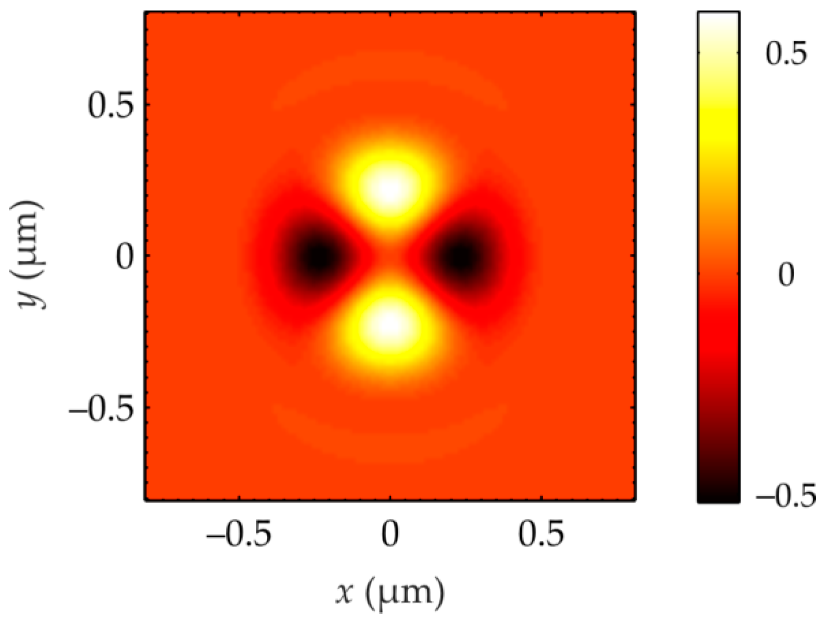
It can be seen from
Figure 1 that the spin density has the form of a Maltese cross, in the upper and lower parts of which the light has right-handed circular (elliptical) polarization since
Sz > 0, and in the left and right parts of the cross, the light has left-handed circular (elliptical) polarization since
Sz < 0.
5.2. Hall Effect at the Focus of a Beam with Hybrid Polarization
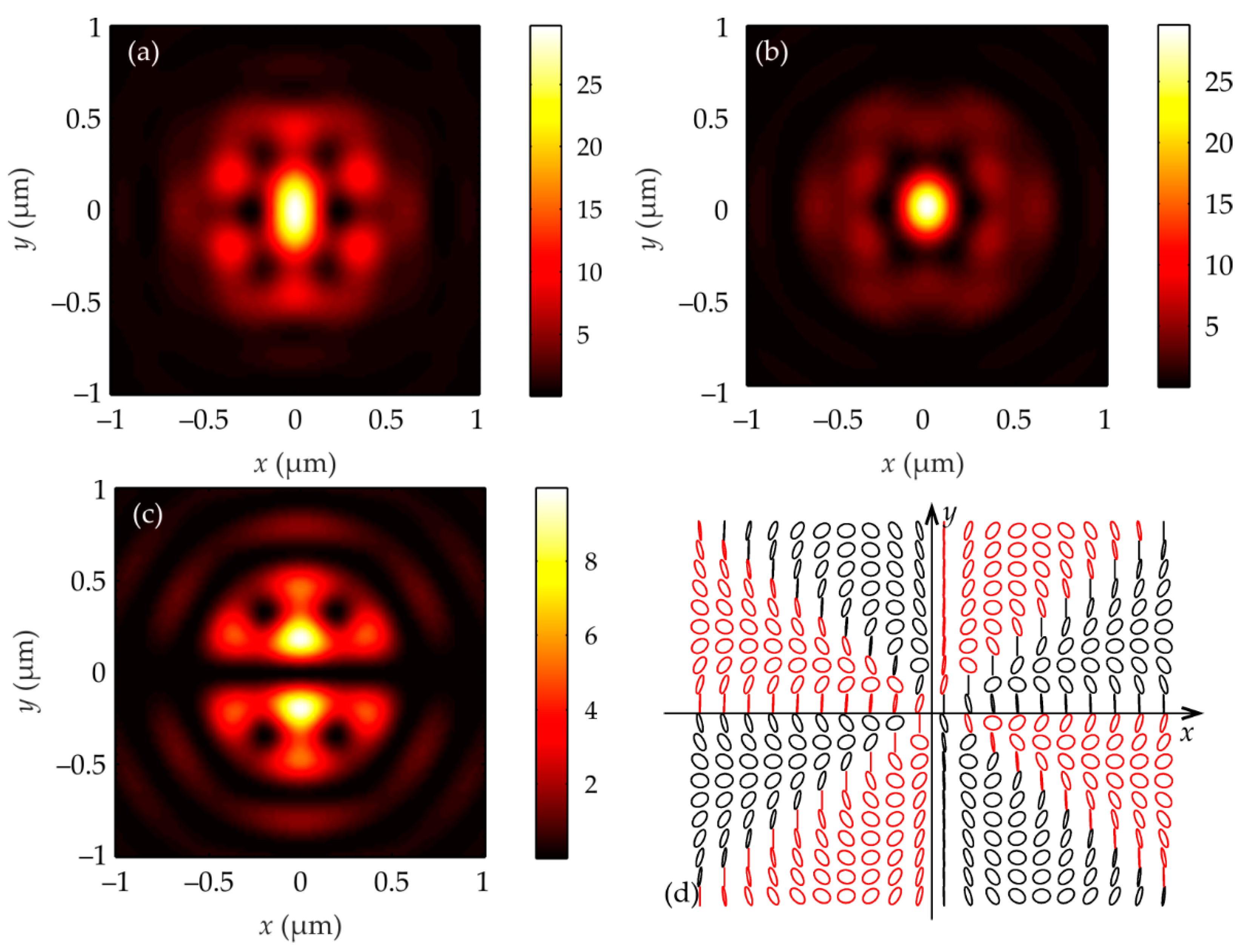
Using the Richards–Wolf formulas, the focusing of a beam (11), which is a superposition of a cylindrical vector beam of the m-th order and a plane wave with linear polarization along the y-axis, was simulated. The wavelength was λ = 532 nm, the order of azimuthal polarization was m = 4, and the parameter a was equal to 1. Focusing was performed with a flat diffractive lens with NA = 0.95.
Figure 2a shows the beam intensity (11) at the focus. It can be seen that the focal spot is an ellipse extended along the polarization axis
y. Furthermore, the intensity in
Figure 2 has six side lobes determined by the longitudinal component (
Figure 2c). The transverse intensity distribution (
Figure 2b) has 2
m = 8 isolated intensity nulls (where the energy flow is zero). The transverse energy flow rotates along a closed trajectory (
Figure 3) around these zeros.
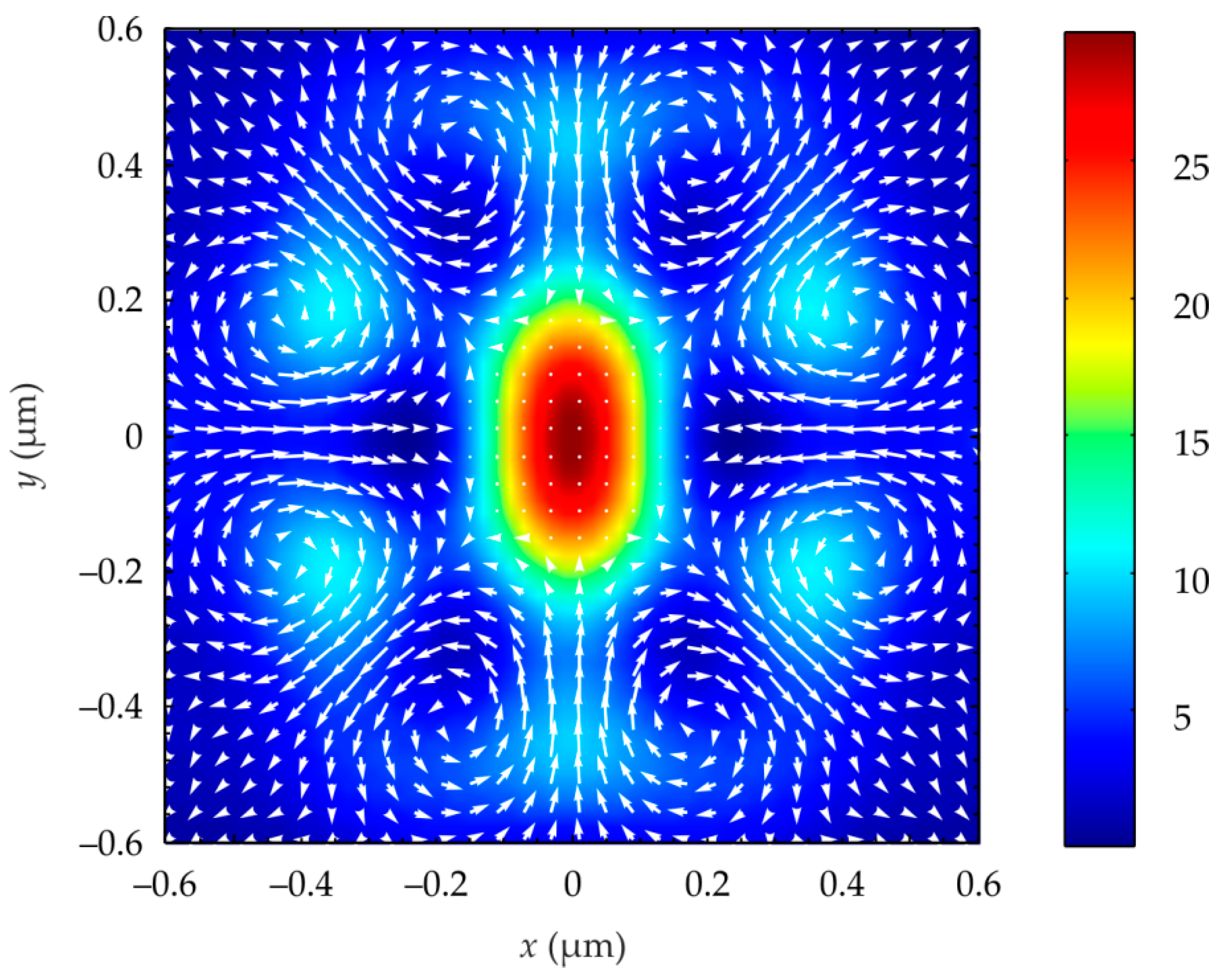
Figure 3 shows an intensity pattern (same as in
Figure 2a) and the direction and magnitude (marked by arrows) of the transverse energy flow
Pxex+
Pyey, where
ex,
ey are the unit vectors of the Cartesian system in the focal plane. It can be seen from
Figure 3 that 2
m = 8 local subwavelength regions with a 200–300 nm diameter formed at the focus. These regions are centered on a certain circle drawn around the optical axis and pass through the intensity zeros surrounding the focal spot. In each of these regions, the transverse energy flow rotates along a closed trajectory. In the neighboring regions, the rotation directions are different. That is, the on-axis OAM projection has a different sign in the neighboring regions. Such a separation in space of transverse energy flows rotating in different directions is a demonstration of the orbital Hall effect of the 2
m-th order.
6. Conclusions
Summing up, using the Richards–Wolf formalism, which adequately describes the behavior of a vector light field at the tight focus, we have shown that if the focal length is much greater than the wavelength, then at the focus of a circularly polarized optical vortex, regions of different-handedness (left- and right-handed) circular polarization are found on different-radius circles centered on the optical axis. That is, photons that fall into focus at different distances from the optical axis have different spins: either left- or right-handed circular polarization. Such an effect can be called the radial spin Hall effect.
We have also shown by using the Richards–Wolf formalism that at the tight focus of a linearly polarized optical vortex with unit topological charge, there are four local subwavelength regions about 200 nm in size (for a 532-nm wavelength and NA = 0.95), with the spin being directed oppositely in the neighboring regions. That is, in two vertically adjacent regions, the longitudinal SAM projection is positive (right-handed elliptical polarization), and in two horizontally adjacent regions, the longitudinal SAM projection is negative (left-handed circular or elliptical polarization). Such a spatial separation of regions with opposite spins at the focus can be called a spin Hall effect of the 4-th order.
We have also shown that at the tight focus of the superposition of cylindrical vector beams with m and zero orders, 2m local regions are formed, with the transverse energy flow rotating in the opposite directions in the neighboring regions. That is, the longitudinal OAM component has different signs in the neighboring regions. This is the orbital Hall effect of the 2m-th order.
These effects arise at the focus due to the conservation of the angular momentum of the beam and due to the spin-to-orbital conversion. In the first example of a linearly polarized optical vortex, the SAM is zero both in the initial plane and at the tight focus. However, in this case, an even number of local subwavelength regions have been shown to occur at the focus, in which the SAM is nonzero and has the opposite signs in the neighboring regions. In this case, the Hall effect occurs due to the orbital-to-spin conversion. In the second example, the superposition of two non-vortex cylindrical beams of the mth and 0th order has zero OAM and non-zero SAM in the source plane. At the focus, 2m subwavelength regions are formed, in which the OAM is nonzero, taking different signs in the neighboring regions. The total OAM at the focus remains zero. In this case, the Hall effect appears due to the spin-to-orbital conversion.
Author Contributions
Conceptualization, V.V.K.; methodology, V.V.K. and S.S.S.; software, S.S.S. and E.S.K.; validation, V.V.K. and S.S.S.; formal analysis, V.V.K.; investigation, V.V.K. and S.S.S.; resources, V.V.K., E.S.K. and M.A.B.; data curation, V.V.K. and S.S.S.; writing—original draft preparation, V.V.K. and E.S.K.; writing—review and editing, V.V.K., E.S.K. and M.A.B.; visualization, S.S.S.; supervision, V.V.K.; project administration, S.S.S. and E.S.K.; funding acquisition, S.S.S. and E.S.K. All authors have read and agreed to the published version of the manuscript.
Funding
The work was funded by the Russian Science Foundation under grant #22-22-00265.
Institutional Review Board Statement
Not applicable.
Informed Consent Statement
Not applicable.
Data Availability Statement
Not applicable.
Conflicts of Interest
The authors declare no conflict of interest. The funders had no role in the design of the study; in the collection, analysis, or interpretation of data; in the writing of the manuscript; or in the decision to publish the results.
References
- Onoda, M.; Marakami, S.; Nagaosa, N. Hall effect of light. Phys. Rev. Lett. 2004, 93, 083901. [Google Scholar] [CrossRef] [PubMed] [Green Version]
- Bliokh, K.Y.; Bliokh, Y.P. Topological spin transport of photons: The optical Magnus effect and Berry phase. Phus. Lett. A 2004, 333, 181–186. [Google Scholar] [CrossRef] [Green Version]
- Bliokh, K.Y.; Bliokh, Y.P. Conservation of angular momentum, transverse shift, and spin Hall effect in reflection and refraction of an electromagnetic wave packet. Phys. Rev. Lett. 2006, 96, 073903. [Google Scholar] [CrossRef] [PubMed] [Green Version]
- Kavokin, A.; Malpuech, G.; Glazov, M. Optical spin Hall effect. Phys. Rev. Lett. 2005, 95, 136601. [Google Scholar] [CrossRef] [PubMed] [Green Version]
- Hosten, O.; Kwiat, P. Observation of the spin Hall effect of light via weak measurements. Science 2008, 319, 787–790. [Google Scholar] [CrossRef] [Green Version]
- Ling, X.; Zhou, X.; Huang, K.; Liu, Y.; Qiu, C.; Luo, H.; Wen, S. Recent advances in the spin Hall effect of light. Pep. Prog. Phys. 2017, 80, 066401. [Google Scholar] [CrossRef] [PubMed] [Green Version]
- Liu, S.; Chen, S.; Wen, S.; Luo, H. Photonics spin Hall effect: Fundamentals and emergent applications. Opto-Electr. Sci. 2022, 1, 220007. [Google Scholar] [CrossRef]
- Ling, X.; Yi, X.; Zhou, X.; Liu, Y.; Shu, W.; Luo, H.; Wen, S. Realization of tunable spin-dependent splitting in intrinsic photonic spin Hall effect. Appl. Phys. Lett. 2014, 105, 151101. [Google Scholar] [CrossRef] [Green Version]
- Yin, X.; Ye, Z.; Rho, J.; Wang, Y.; Zhang, X. Photonic spin Hall effect at metasurfaces. Science 2013, 339, 1405. [Google Scholar] [CrossRef] [Green Version]
- Kumar, R.N.; Yatish; Gupta, S.D.; Ghosh, N.; Banerjee, A. Probing the rotational spin-Hall effect in a structured Gaussian beam. Phys. Rev. A 2022, 105, 023503. [Google Scholar] [CrossRef]
- Zhang, J.; Zhou, X.; Ling, X.; Chrn, S.; Luo, H.; Wen, S. Orbit-orbit interaction and photonics orbital Hall effect in reflection of a light beam. Chin. Phys. B 2014, 23, 064215. [Google Scholar] [CrossRef]
- Fu, S.; Guo, C.; Liu, G.; Li, Y.; Yin, H.; Li, Z.; Chen, Z. Spin-orbit optical Hall effect. Phys Rev. Lett. 2019, 123, 243904. [Google Scholar] [CrossRef] [PubMed]
- Zhang, F.; Guo, Y.; Pu, M.; Li, X.; Ma, X.; Luo, X. Metasurfaces enabled by asymmetric photonic spin-orbit interactions. Opto-Electr. Eng. 2020, 47, 200366. [Google Scholar]
- Shu, W.; Lin, C.; Wu, J.; Chen, S.; Ling, X.; Zhou, X.; Luo, H.; Wen, S. Three-dimensional spin Hall effect of light in tight focusing. Phys. Rev. A 2020, 101, 023819. [Google Scholar] [CrossRef]
- Bliokh, K.Y.; Ostrovskaya, E.A.; Alonso, M.A.; Rodriguez-Herrera, O.G.; Lara, D.; Dainty, C. Spin-to-orbital angular momentum conversion in focusing, scattering, and imaging systems. Opt Express. 2011, 19, 26132–26149. [Google Scholar] [CrossRef] [PubMed] [Green Version]
- Man, Z.; Xi, Z.; Yuan, X.; Burge, R.E.; Paul Urbach, H. Dual Coaxial Longitudinal Polarization Vortex Structures. Phys. Rev. A 2020, 86, 053836. [Google Scholar] [CrossRef] [Green Version]
- Richards, B.; Wolf, E. Electromagnetic Diffraction in Optical Systems. II. Structure of the Image Field in an Aplanatic System. Proc. R. Soc. A. Math. Phys. Eng. Sci. 1959, 253, 358–379. [Google Scholar]
- Kotlyar, V.V.; Nalimov, A.G.; Stafeev, S.S. Exploiting the circular polarization of light to obtain a spiral energy flow at the subwavelength focus. J. Opt. Soc. Am. B. 2019, 36, 2850–2855. [Google Scholar] [CrossRef]
- Kotlyar, V.V.; Kovalev, A.A.; Nalimov, A.G. Energy density and energy flux in the focus of an optical vortex: Reverse flux of light energy. Opt. Lett. 2018, 43, 2921–2924. [Google Scholar] [CrossRef]
- Kotlyar, V.; Stafeev, S.; Zaitsev, V.; Kozlova, E. Spin-Orbital Conversion with the Tight Focus of an Axial Superposition of a High- Order Cylindrical Vector Beam and a Beam with Linear Polarization. Micromachines 2022, 13, 1112. [Google Scholar] [CrossRef]
- Kotlyar, V.V.; Kovalev, A.A.; Stafeev, S.S.; Nalimov, A.G.; Rasouli, S. Tightly focusing vector beams containing V-point polarization singularities. Opt. Laser Technol. 2022, 145, 107479. [Google Scholar] [CrossRef]
- Gonoskov, I.; Aiello, A.; Heugel, S.; Leuchs, G. Dipole pulse theory: Maximizing the field amplitude from 4π focused laser pulses. Phys. Rev. Lett. 2012, 124, 103901. [Google Scholar]
| Publisher’s Note: MDPI stays neutral with regard to jurisdictional claims in published maps and institutional affiliations. |
© 2022 by the authors. Licensee MDPI, Basel, Switzerland. This article is an open access article distributed under the terms and conditions of the Creative Commons Attribution (CC BY) license (https://creativecommons.org/licenses/by/4.0/).


