Generation of Uniform X-ray Illumination and Its Application to X-ray Diffraction Microscopy


1
Faculty of Electronics, Photonics and Microsystems, Wrocław University of Science and Technology, Wybrzeże Stanisława Wyspiańskiego 27, 50-370 Wrocław, Poland
2
Institute of Physics, ELI Beamlines, Academy of Sciences of the Czech Republic, Na Slovance 1999/2, 18221 Prague, Czech Republic
*
Author to whom correspondence should be addressed.
Photonics 2022, 9(12), 934; https://doi.org/10.3390/photonics9120934
Submission received: 28 October 2022
/
Revised: 29 November 2022
/
Accepted: 30 November 2022
/
Published: 3 December 2022
(This article belongs to the Special Issue XUV and X-ray Free-Electron Lasers and Applications)
Abstract
:X-ray diffraction microscopy (XDM) is an established lens-less imaging method extensively practiced at synchrotrons and X-ray free-electron lasers (XFELs). XDM is broadly operated in two different modes: scanning and non-scanning. The non-scanning mode of operation in XDM is commonly called coherent diffraction imaging (CDI) and has been the key research direction of many XFEL facilities. This method typically images objects smaller than the size of the illumination, which precludes the imaging of a large group of samples physically larger than the illumination. Furthermore, satisfying this requirement at X-ray free-electron lasers tremendously reduces the volume of practically useful data, leading the experimental scheme to be less efficient. Such a limitation can be circumvented by using a uniform illumination probe rather than the traditional Gaussian-focused probe from the X-ray focusing optics. Here in this article, we report a numerical study on the design of an optical element to generate uniform X-ray illumination and its application to the CDI. We demonstrate the benefits of such illumination in imaging objects that are larger than the illumination size and in improving the efficiency of the experimental scheme overall.
1. Introduction
X-ray diffraction microscopy is an established lens-less imaging method that has evolved significantly over the past two decades [1,2,3,4,5]. The method has become a standard microscopic tool for the two-dimensional and three-dimensional nano-scale imaging of objects at synchrotrons. The extension of the method with electrons [6] and visible lights [7,8,9] has also been demonstrated on a few occasions. With the advent of X-ray free-electron lasers (XFELs), the method has received significant attention, and several XFELs have included the development of this method as one of their main research programs. The objective of such programs is to perform radiation damage-free imaging of cells to molecules, exploiting the concept behind the “diffraction before destruction” [10]. In a typical XDM experiment, a coherent illumination shines the sample, and a speckled diffraction pattern is recorded with a two-dimensional detector. An image of the specimen is obtained after retrieving the phase by using standard phase-retrieval algorithms [11,12,13] where the measured diffraction is taken as the input. In one of the variants of XDM, which operates in a non-scanning mode, the sample dimensions should be smaller than the illumination size in order to satisfy the oversampling requirement in practice. This method is widely called coherent diffraction imaging (CDI).
XDM methods to image samples larger than the illumination size do exist and are broadly known in the community by the name of Ptychography [14,15,16,17,18,19,20]. In these methods, the illumination raster scans the extended sample with each consecutive scan overlapping by a significant fraction, and a diffraction pattern is recorded at each scan point. The image of the extended sample is then obtained using the iterative algorithm. The limitation of this method is that it is not the method of choice for the single-shot experiments practiced at XFELs where the sample is completely damaged after the X-ray illuminates the sample.
The imaging of an extended sample by coherent diffraction imaging in a non-scanning mode has been demonstrated on a few occasions [21,22]. The solutions presented are not optimal as they either need the information of the illuminating wavefront or need the knowledge of the intensity distribution to obtain the intrinsic density distribution of the sample. Additionally, approaches such as the coherent modulation of the exit wave and randomized probe imaging have also been demonstrated to image extended objects in the non-scanning mode. However, these methods need the information of either the modulator or the probe beforehand for carrying out any successful reconstruction of the image [23,24]. These problems can be resolved if uniform illumination can be used for coherent diffraction imaging. Additionally, the low hit rates in the current XFEL experiments can be overcome with such illumination and the entire measurement scheme can be made more efficient. This article aims at exploring this possibility through numerical simulations.
Attempts to generate uniform X-ray illumination have previously been demonstrated by the use of the diffractive optical element [25,26]. However, in the majority of the previous reports, only uniform intensities over the illumination were obtained. For applications aiming at coherent diffraction imaging, both the intensity distribution and the phase distribution need to be uniform. Diffractive optical elements capable of generating such illumination with a uniform amplitude and phase have recently been demonstrated in the visible-light regime [27]. Here in this report, we extend the use of the knowledge existing in the visible-light regime and design an optical element to generate illumination with a uniform X-ray intensity and phase. Such beams are then applied for coherent diffraction imaging to show their benefits in imaging extended objects and also to improve the efficiency of the experiments.
2. Experimental Setup and Design of the Phase Grating
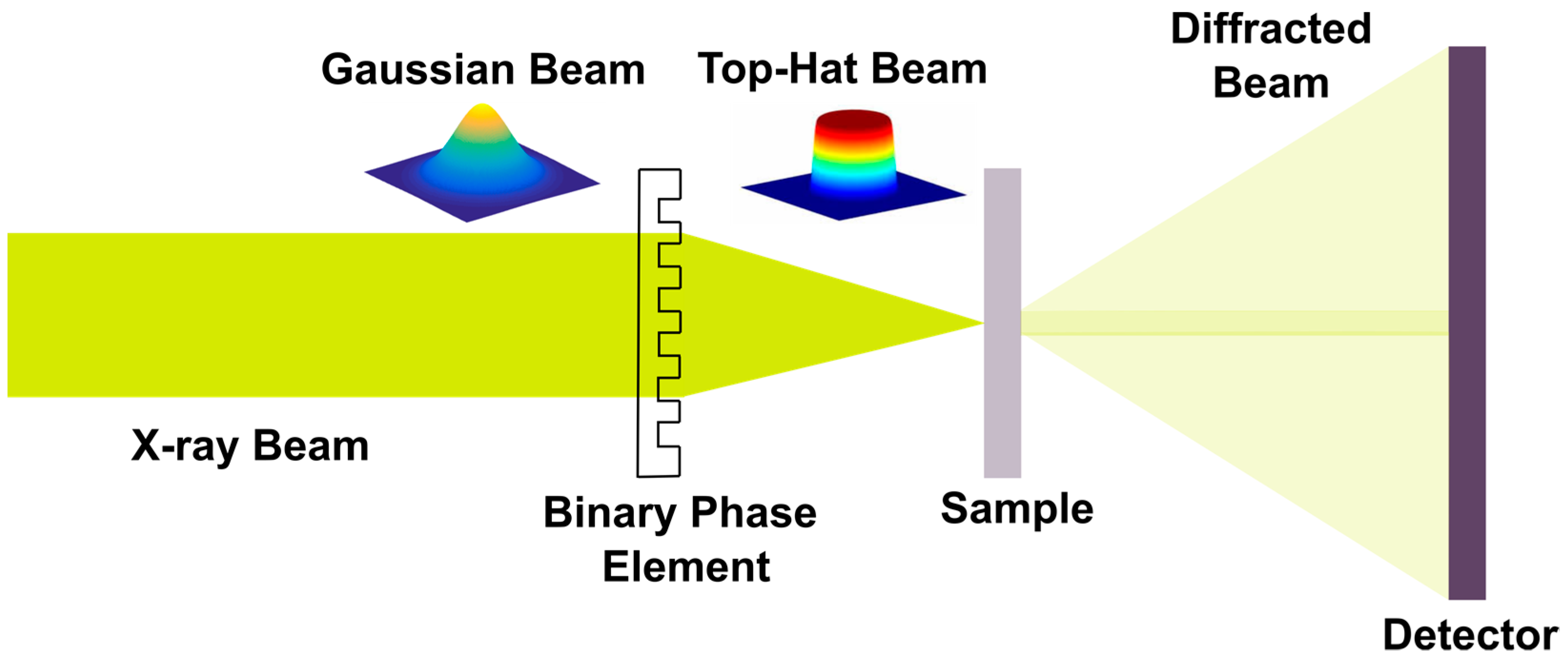
A schematic for the proposed experiment to transform the Gaussian beam into a top-hat beam with a uniform phase and its application to diffraction imaging is shown in Figure 1. The schematic is designed assuming the input to the optical element is a Gaussian beam. All the simulation results presented in this article are based on the above schematics. Furthermore, we assume that the incident illumination has full spatial coherence. We also assume that the incident beam is fully monochromatic. In brief, a Gaussian beam passes through the optical element. At the Fresnel regime of the optical element, a top-hat beam is generated. Such a top-hat beam illuminates the sample, and a speckled diffraction pattern in the Fraunhoffer regime is recorded by a two-dimensional detector.
2.1. Design of the Optical Element
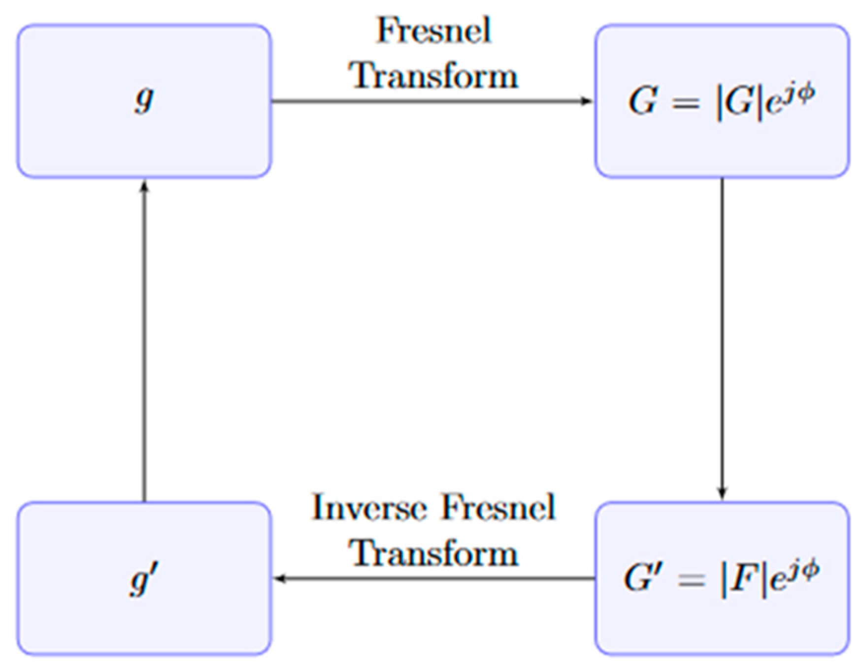
The design of the optical element is one of the key results presented in this article. In this section, we describe the procedure for obtaining such an optical element. We have used the modified Gerchberg–Saxton (GS) algorithm as proposed by Reddy et al. [27]. The modified GS algorithm has constant amplitude as a constraint in the input space, which means that only phase of the new function from each iteration in the input space is updated and the amplitude is retained. The proposed algorithm has been adapted to the X-ray wavelengths (1.24 Å) and used for designing the optical element. In brief, the algorithm takes an input beam g with Gaussian distribution and random phase. The input beam is then Fresnel propagated to a distance of 10−2 m to obtain a new field G. At this plane, the amplitude of G is replaced by the amplitude of the desired top-hat beam while the phase is retained. This new distribution G’, after spatial filtering, is back-propagated to the plane of the optical element using inverse Fresnel propagation to obtain g’. This process is continued until an optical element necessary for obtaining illumination with uniform phase and intensity is obtained. The convergence of the algorithm was monitored by a root mean square error (RMSE) as defined in Equation (1). For different trials we have performed during the simulation, the convergence is confirmed after the RMSE error reaches a value of 10−8, which on an average would take ~5000 iterations. A schematic representation of the algorithm used for designing the optical element is shown in Figure 2.
2.2. Description of the Optical Grating
With the algorithm defined in the previous section, we have designed the optical element necessary to convert the Gaussian X-ray beam to a top-hat X-ray beam with uniform phases. The summary of the input parameters used for the simulation has been presented in Table 1. The parameters are taken from the standard experiments being performed at the XFELs.
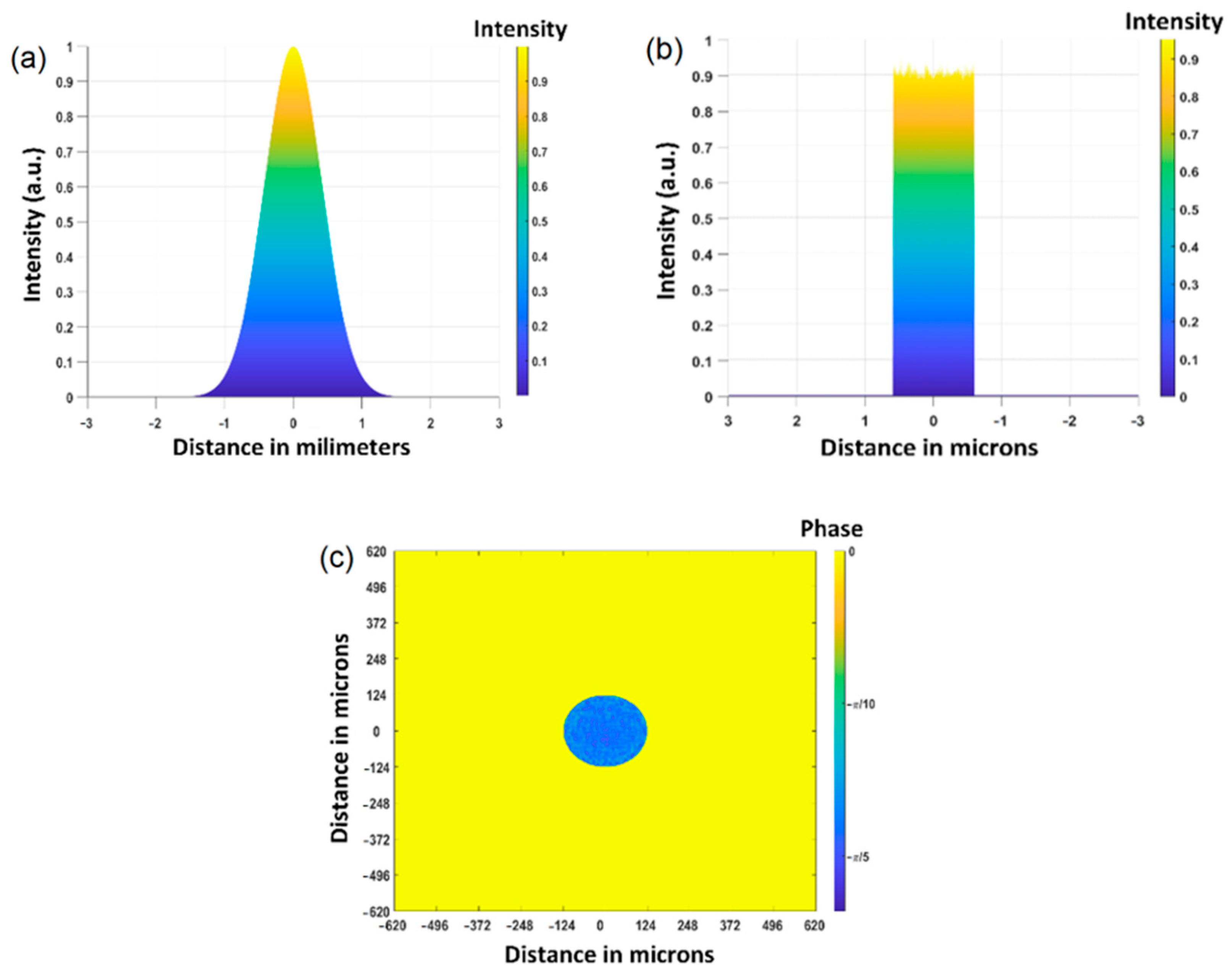
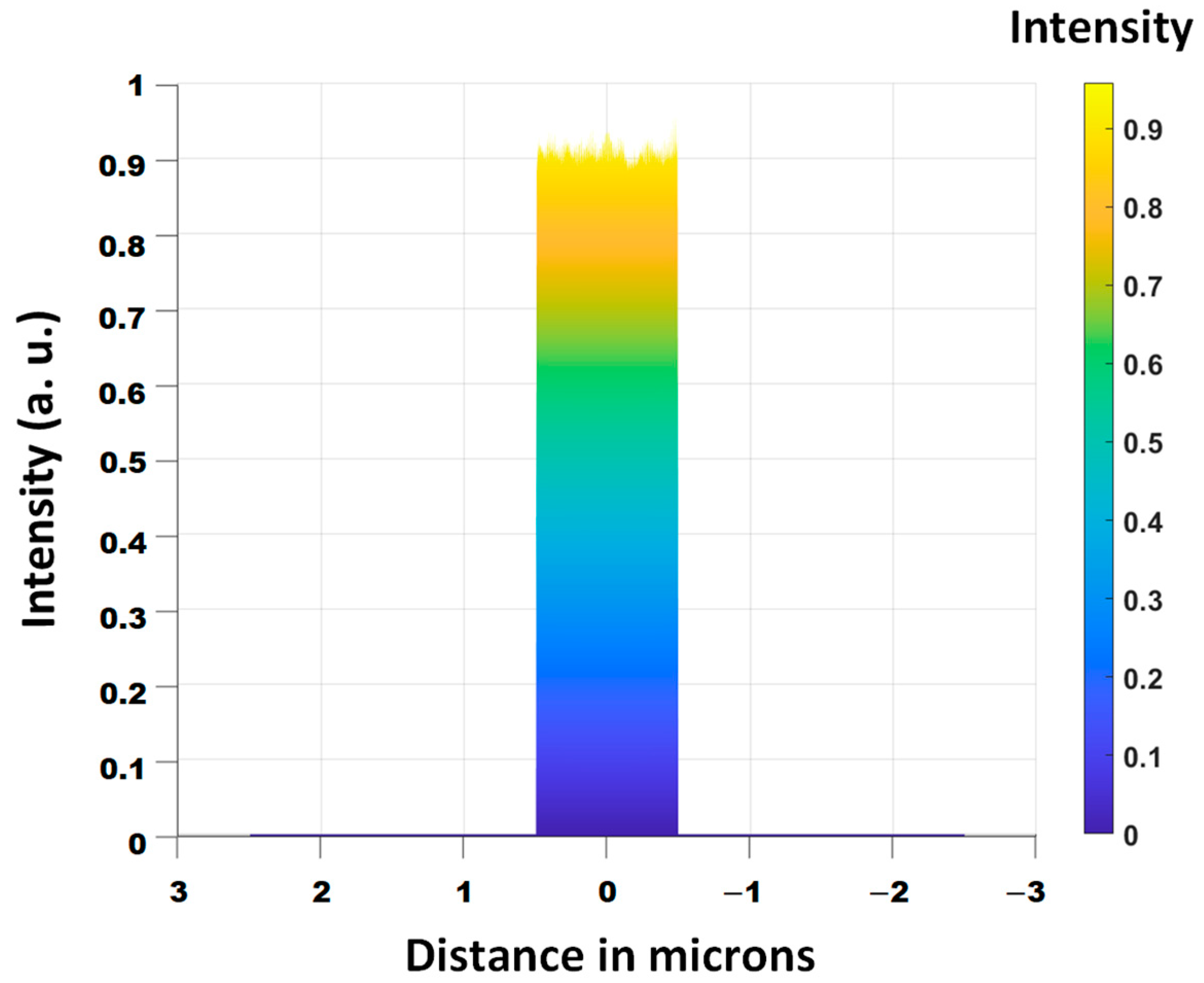
The results obtained from the simulation have been summarized in Figure 3. The input beam with Gaussian intensity distribution is shown in Figure 3a. The output beam with the uniform intensity is shown in Figure 3b. The output top-hat beam showed no higher-order diffraction intensities. The phase distribution of the top-hat beam is shown in Figure 3c.
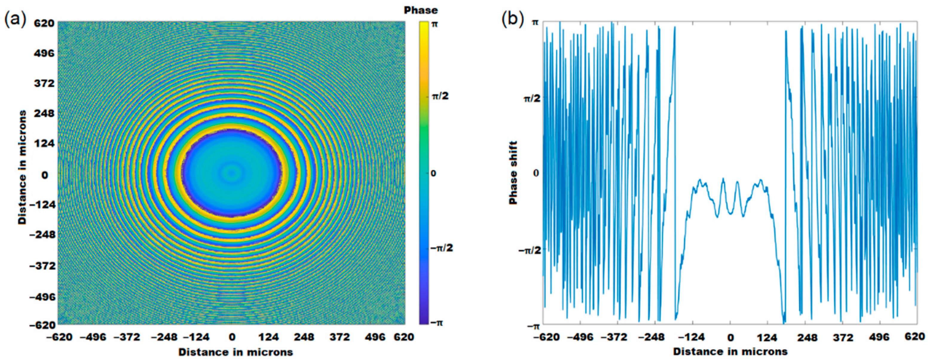
The targeted size of the top-hat beam is 1 µm. From the simulation, the phase element necessary to generate the illumination with uniform phase and intensity has dimensions of 1.24 mm by 1.24 mm. The optical element is comprised of concentric rings with a width of a maximum of ~57 µm. At the plane of the phase element, each pixel corresponds to ~1.24 µm. The phase distribution in the optical element simulated for the conditions described in Table 1 is shown in Figure 4a. A line plot of the phase element is shown in Figure 4b. From the phase profile of the phase element, the phase difference between the maxima and the minima of the concentric rings ranges up to 2π and is not uniform. Although they are comprised of concentric rings, they should not be confused with the traditional zone plates. Unlike zone plates, the phase element necessary to produce the top-hat beam is not a periodic square function with varying widths. Because the phase is linearly dependent on the thickness of the material used for fabricating the phase element, such a phase element can be fabricated the same way as the blazed diffractive elements are, but this can be challenging. Alternatively, such phase distributions can also potentially be generated using X-ray wavefront shaping elements [28]. The smallest feature size that needs to be patterned is 4.96 µm. The fabrication of such a transmission phase element can be performed by making patterns of silicon on the silicon nitride membrane. Based on the necessary phase shift to be introduced, the thickness of the silicon can be calculated with t = φλ/2δπ, where t is the thickness, φ is the phase shift, λ is the wavelength, δ is the real part of the refractive index. For silicon, δ has a value of ~4.31·10−6 at ~10 keV. Because the maximum phase shift necessary for the proposed phase element is 2π, the maximum thickness of silicon to be deposited is ~28.77 µm. At 10 keV, approximately 19% of the total flux is absorbed.
We also performed a simulation to test the manufacture tolerance of the optical element. In the simulations, we observed that the addition of a random phase noise equivalent to ±5 nm roughness maintained the uniform intensities and phase in the illumination. Figure 5 shows the top-hat beam obtained after adding ±5 nm to the phase element shown in Figure 4a.
3. Coherent Diffraction Imaging of Extended Objects
Illumination with a uniform phase and intensity can find practical applications in coherent diffraction imaging. As discussed in the introduction, it can be used in the imaging of extended objects. To verify this, we have performed a numerical simulation. We used an exemplary “Lena” image, as shown in Figure 6a, converted from RGB to grayscale. Post conversion to grayscale, the intensity distribution in the image was converted to phase values ranging from 0 to 2π. The image dimensions are reshaped in order to make it larger than that of the illumination. For both the Gaussian and the top-hat beam, the central part of the sample was illuminated by the probes. The exit waves obtained after the interaction of the sample by the Gaussian and top-hat illuminations are shown in Figure 6b,e, respectively. The diffraction patterns shown in Figure 6d,g were obtained by taking the modulus square of the Fourier transform of the exit wave. A visual comparison of the two diffraction patterns shows no effect of any sort of higher-order diffraction rings in the top-hat beam. These diffraction patterns were then used as the input for the phase-retrieval algorithm. In this study, we have used the shrinkwrap hybrid–input–output (HIO) algorithm to perform all the reconstructions. The choice of the shrinkwrap HIO is merely to make the method work without any prior information on the beam dimension or profile. A detailed description of the algorithm can be found elsewhere [12,29]. A comparison of the reconstruction using the Gaussian beam and the top-hat beam is shown in Figure 6c,f, respectively. The reconstructions presented are after the 500 iterations of the shrinkwrap HIO. From the images, it can be observed that the fidelity of the reconstructions made from the top-hat beam is much higher than those reconstructed from the Gaussian beam.
4. A Study of the Hit-Rate Improvement with the Top-Hat Beam
The hit rate in a typical XFEL CDI experiment is defined as the ratio of any hit on the sample by the X-ray beam to the total number of frames collected during the experiment. However, a practical fact is that not all the collected diffraction patterns are reconstructible. The ones obtained by the tail of the beam hitting the samples or by the non-planar region of the wavefront lead to a poor or even failed reconstruction. Moreover, the scattering pattern from the sample molecule depends on the position of the beam hitting the sample [30]. Therefore, the real volume of practically useful data is much less than that defined by the hit rates. This section presents the impact of the beam profile in increasing the volume of the reconstructible data.
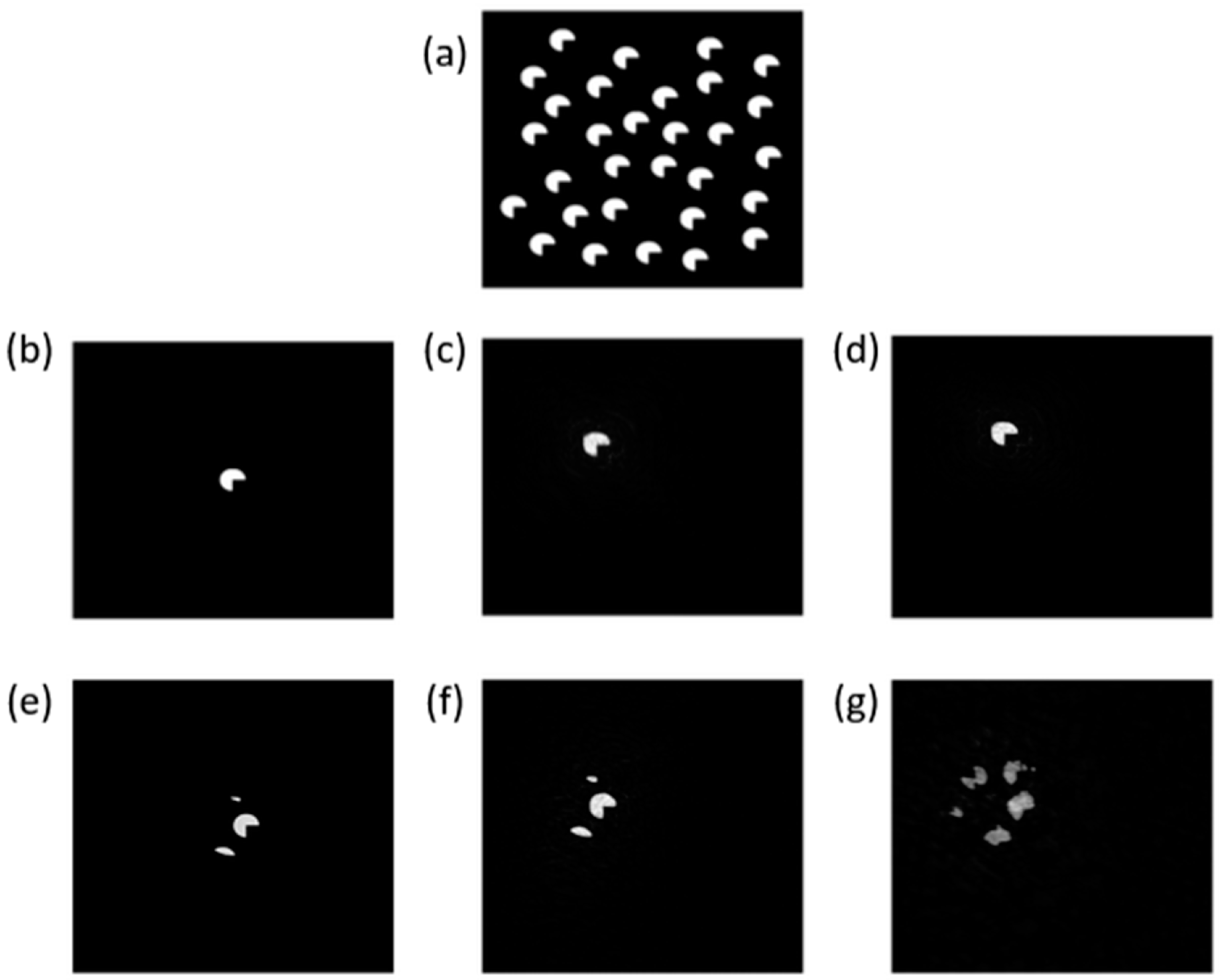
In order to study whether top-hat beams provide superior hit rates as compared to the Gaussian probe, in terms that they can provide a larger volume of practically useful data, we have carried out simulations with a test specimen. Our specimen consists of the two-dimensional random distribution of particles, as shown in Figure 7a. To see the impact of the beam profile on the volume of useful data, we have generated 100 images with random particles, with two subgroups, one containing only individual particles in the beam and the other containing multiple particles in the beam, which resembles the experimental conditions. Such test specimens were generated by varying the number (density) of particles in Figure 7a. The size of each particle in the test specimen is ~500 nm. Because the FWHM of the top-hat and the Gaussian beams were simulated to be 1 µm, we confirm that single particles and multiple particles were hit for the cases defined above.
An instance of the reconstruction for a single particle in the illumination volume with a top-hat beam and a Gaussian beam is shown in Figure 7c,d, respectively. Similarly, the reconstructions for the multiple particles in the sample volume are shown in Figure 7f,g, respectively. The samples used for the two cases are shown in Figure 7b,e, respectively. All the reconstructions presented in this section were obtained after 500 iterations of the HIO algorithm, in which the first 200 were performed by using dynamic support and the last 300 were with fixed support. In order to make the quantitative comparisons of the reconstructions using the Gaussian beam and the top-hat beam, we have defined a contrast function:
A plot of the contrast function for the reconstructions in both cases is shown in Figure 8. From the plot, it is obvious that for the overall data, the reconstruction from the top-hat beam performs better than the reconstructions from the Gaussian beam. Taking a threshold of the contrast value 0.33 (corresponding to the S/N ratio of 3:1), we found that 58 images were successfully reconstructed by the Gaussian beam while all the images were successfully reconstructed by the top-hat beam. The peak values in the plot for the reconstruction with both beams showed the inconsistency in the reconstruction. Furthermore, from our studies, we observed that, overall, the contrast in the reconstructed image was enhanced by a factor as high as ~10 times and on average by a factor of 1.35 times with the use of the top-hat beam.
5. Conclusions
To summarize, we have proposed a design of the optical element to generate the top-hat X-ray beam and have shown the usefulness of the top-hat beam in performing X-ray diffraction imaging of extended images. The design proposed here can be adapted for different X-ray wavelengths, such as the ones operating in the soft X-ray regime and Extreme UV regime. We also show that the hit rate, which we define as the ratio of the practically useful data giving a reasonable reconstruction and the total volume of the data collected of the single particle X-ray diffraction imaging practiced at XFELs, can be improved by the use of the top-hat beam. This in turn makes the XFEL coherent diffraction imaging more efficient. Furthermore, the use of a top-hat beam can also lead to the beam-stop-less experiments for X-ray CDI, thus making the low-resolution information more accessible. The proposed scheme for the top-hat beam generation can also be used in X-ray Ptychography to decrease the dynamic range in the diffraction pattern and thus make the recording of high-resolution information easier [31]. Further, such uniform illumination will also be preferred in X-ray pump-probe experiments where the uniform excitation of the sample is desired. An experiment to validate the proposition made in this article will be performed in the near future.
Author Contributions
Conceptualization, K.P.K.; Methodology, K.K. and K.P.K.; Software, K.K.; Investigation, K.K., S.E. and K.P.K.; Writing—original draft, K.K. and K.P.K.; Writing—review & editing, K.P.K. All authors have read and agreed to the published version of the manuscript.
Funding
We acknowledge the funding from the projects “Advanced research using high-intensity laser produced photons and particles” (CZ.02.1.01/0.0/0.0/16019/0000789) and “Structural Dynamics of Biomolecular Systems” (ELIBIO) (CZ.02.1.01/0.0/0.0/15003/0000447) from the European Regional Development Fund. The work was also supported by funding from the large infrastructures (LM2018141).
Institutional Review Board Statement
Not applicable.
Informed Consent Statement
Not applicable.
Data Availability Statement
Not applicable.
Conflicts of Interest
The authors declare no conflict of interest.
References
- Miao, J.; Charalambous, P.; Kirz, J.; Sayre, D. Extending the methodology of X-ray crystallography to allow imaging of micrometre-sized non-crystalline specimens. Nature 1999, 400, 342–344. [Google Scholar] [CrossRef]
- Miao, J.; Hodgson, K.O.; Ishikawa, T.; Larabell, C.A.; LeGros, M.A.; Nishino, Y. Imaging whole Escherichia coli bacteria by using single-particle X-ray diffraction. Proc. Natl. Acad. Sci. USA 2003, 100, 110–112. [Google Scholar] [CrossRef] [PubMed] [Green Version]
- Nishino, Y.; Takahashi, Y.; Imamoto, N.; Ishikawa, T.; Maeshima, K. Three-dimensional visualization of a human chromosome using coherent X-ray diffraction. Phys. Rev. Lett. 2009, 102, 018101. [Google Scholar] [CrossRef] [PubMed]
- Seibert, M.M.; Ekeberg, T.; Maia, F.R.N.C.; Svenda, M.; Andreasson, J.; Jönsson, O.; Odić, D.; Iwan, B.; Rocker, A.; Westphal, D.; et al. Single mimivirus particles intercepted and imaged with an X-ray laser. Nature 2011, 470, 78–81. [Google Scholar] [CrossRef] [Green Version]
- Ekeberg, T.; Svenda, M.; Abergel, C.; Maia, F.R.; Seltzer, V.; Claverie, J.M.; Hantke, M.; Jönsson, O.; Nettelblad, C.; van der Schot, G.; et al. Three-dimensional reconstruction of the giant mimivirus particle with an X-ray free-electron laser. Phys. Rev. Lett. 2015, 114, 098102. [Google Scholar] [CrossRef] [Green Version]
- Zuo, J.M.; Vartanyants, I.; Gao, M.; Zhang, R.; Nagahara, L.A. Atomic resolution imaging of a carbon nanotube from diffraction intensities. Science 2003, 300, 1419–1421. [Google Scholar] [CrossRef] [Green Version]
- Latychevskaia, T.; Longchamp, J.-N.; Fink, H.-W. When holography meets coherent diffraction imaging. Opt. Express 2012, 20, 28871–28892. [Google Scholar] [CrossRef] [Green Version]
- Marathe, S.; Kim, S.S.; Kim, S.N.; Kim, C.; Kang, H.C.; Nickles, P.V.; Noh, D.Y. Coherent diffraction surface imaging in reflection geometry. Opt. Express 2010, 18, 7253–7262. [Google Scholar] [CrossRef]
- Khakurel, K.P.; Kimura, T.; Joti, Y.; Matsuyama, S.; Yamauchi, K.; Nishino, Y. Coherent diffraction imaging of non-isolated object with apodized illumination. Opt. Express 2015, 23, 28182–28190. [Google Scholar] [CrossRef]
- Neutze, R.; Wouts, R.; van der Spoel, D.; Weckert, E.; Hajdu, J. Potential for biomolecular imaging with femtosecond X-ray pulses. Nature 2000, 406, 752–757. [Google Scholar] [CrossRef]
- Fienup, J.R. Phase retrieval algorithms: A comparison. Appl. Opt. 1982, 21, 2758–2769. [Google Scholar] [CrossRef] [PubMed] [Green Version]
- Marchesini, S.; He, H.; Chapman, H.N.; Hau-Riege, S.P.; Noy, A.; Howells, M.R.; Weierstall, U.; Spence, J.C.H. X-ray image reconstruction from a diffraction pattern alone. Phys. Rev. B 2003, 68, 140101. [Google Scholar] [CrossRef] [Green Version]
- Luke, D.R. Relaxed averaged alternating reflections for diffraction imaging. Inverse Probl. 2005, 21, 37–50. [Google Scholar] [CrossRef] [Green Version]
- Rodenburg, J.M.; Hurst, A.C.; Cullis, A.G.; Dobson, B.R.; Pfeiffer, F.; Bunk, O.; David, C.; Jefimovs, K.; Johnson, I. Hard-X-Ray Lensless Imaging of Extended Objects. Phys. Rev. Lett. 2007, 98, 034801. [Google Scholar] [CrossRef] [PubMed] [Green Version]
- Thibault, P.; Dierolf, M.; Menzel, A.; Bunk, O.; David, C.; Pfeiffer, F. High-resolution scanning X-ray diffraction microscopy. Science 2008, 321, 379–382. [Google Scholar] [CrossRef]
- Pfeiffer, F. X-ray ptychography. Nat. Photonics 2018, 12, 9–17. [Google Scholar] [CrossRef]
- Baksh, P.D.; Ostrčil, M.; Miszczak, M.; Pooley, C.; Chapman, R.T.; Wyatt, A.S.; Springate, E.; Chad, J.E.; Deinhardt, K.; Frey, J.G.; et al. Quantitative and correlative extreme ultraviolet coherent imaging of mouse hippocampal neurons at high resolution. Sci. Adv. 2020, 6, eaaz3025. [Google Scholar] [CrossRef]
- Tanksalvala, M.; Porter, C.L.; Esashi, Y.; Wang, B.; Jenkins, N.W.; Zhang, Z.; Miley, G.P.; Knobloch, J.L.; McBennett, B.; Horiguchi, N.; et al. Nondestructive, high-resolution, chemically specific 3D nanostructure characterization using phase-sensitive EUV imaging reflectometry. Sci. Adv. 2021, 7, eabd9667. [Google Scholar] [CrossRef]
- Eschen, W.; Loetgering, L.; Schuster, V.; Klas, R.; Kirsche, A.; Berthold, L.; Steinert, M.; Pertsch, T.; Gross, H.; Krause, M.; et al. Material-specific high-resolution table-top extreme ultraviolet microscopy. Light Sci. Appl. 2022, 11, 117. [Google Scholar] [CrossRef]
- Brooks, N.J.; Wang, B.; Binnie, I.; Tanksalvala, M.; Esashi, Y.; Knobloch, J.L.; Nguyen, Q.L.; McBennett, B.; Jenkins, N.W.; Gui, G.; et al. Temporal and spectral multiplexing for EUV multibeam ptychography with a high harmonic light source. Opt. Exp. 2022, 30, 30331–30346. [Google Scholar] [CrossRef]
- Abbey, B.; Nugent, K.; Williams, G.J.; Clark, J.N.; Peele, A.G.; Pfeifer, M.A.; De Jonge, M.; McNulty, I. Keyhole coherent diffractive imaging. Nat. Phys. 2008, 4, 394–398. [Google Scholar] [CrossRef] [Green Version]
- Khakurel, K.P.; Kimura, T.; Nakamori, H.; Goto, T.; Matsuyama, S.; Sasaki, T.; Takei, M.; Kohmura, Y.; Ishikawa, T.; Yamauchi, K.; et al. Generation of apodized X-ray illumination and its application to scanning and diffraction microscopy. J. Synchrotron Radiat. 2017, 24, 142–149. [Google Scholar] [CrossRef] [Green Version]
- Zhang, F.; Chen, B.; Morrison, G.R.; Vila-Comamala, J.; Guizar-Sicairos, M.; Robinson, I.K. Phase retrieval by coherent modulation imaging. Nat. Commun. 2016, 7, 13367. [Google Scholar] [CrossRef] [PubMed]
- Levitan, A.L.; Keskinbora, K.; Sanli, U.T.; Weigand, M.; Comin, R. Single-frame far-field diffractive imaging with randomized illumination. Opt. Express 2020, 28, 37103–37117. [Google Scholar] [CrossRef]
- Jefimovs, K.; Vila-Comamala, J.; Stampanoni, M.; Kaulich, B.; David, C. Beam-shaping condenser lenses for full-field transmission X-ray microscopy. J. Synchrotron Radiat. 2008, 15, 106–108. [Google Scholar] [CrossRef] [Green Version]
- Vogt, U.; Lindblom, M.; Charalambous, P.; Kaulich, B.; Wilhein, T. Condenser for Koehler-like illumination in transmission X-ray microscopes at undulator sources. Opt. Lett. 2006, 31, 1465–1467. [Google Scholar] [CrossRef] [Green Version]
- Reddy, A.N.K.; Pal, V.; Mahler, S.; Friesem, A.A.; Davidson, N. Flat-top laser beams over an extended range. J. Phys. Conf. Ser. 2019, 1410, 012126. [Google Scholar] [CrossRef]
- Mimura, H.; Handa, S.; Kimura, T.; Yumoto, H.; Yamakawa, D.; Yokoyama, H.; Matsuyama, S.; Inagaki, K.; Yamamura, K.; Sano, Y.; et al. Breaking the 10 nm barrier in hard-X-ray focusing. Nat. Phys. 2010, 6, 122–125. [Google Scholar] [CrossRef] [Green Version]
- Fienup, J.R. Reconstruction of an object from the modulus of its Fourier transform. Opt. Lett. 1978, 3, 27–29. [Google Scholar] [CrossRef] [Green Version]
- Liu, H.; Spence, J.C.H. XFEL data analysis for structural biology. Quant. Biol. 2016, 4, 159–176. [Google Scholar] [CrossRef]
- Maiden, A.M.; Rodenburg, J.M.; Humphry, M.J. Optical ptychography: A practical implementation with useful resolution. Opt. Lett. 2010, 35, 2585–2587. [Google Scholar] [CrossRef] [PubMed]
Figure 1.
Schematic for the proposed coherent X-ray diffraction imaging with uniform illumination.

Figure 2.
Gerchberg–Saxton algorithm used in the design of the optical element.

Figure 3.
(a) Input Gaussian beam; (b) output top-hat beam; (c) phase distribution of the output top-hat beam.
Figure 3.
(a) Input Gaussian beam; (b) output top-hat beam; (c) phase distribution of the output top-hat beam.

Figure 4.
(a) The optical element and (b) line plot along the center of the phase element.

Figure 5.
Plot of the top-hat beam obtained after the addition of the random noise to the optical element.
Figure 5.
Plot of the top-hat beam obtained after the addition of the random noise to the optical element.

Figure 6.
(a) Lena image as the test specimen for simulation; (b) exit wave from Gaussian illumination; (c) reconstruction using Gaussian illumination; (d) diffraction pattern from (b); (e) exit wave from top-hat illumination; (f) reconstruction using top-hat illumination; and (g) diffraction pattern from (e).

Figure 7.
(a) Test sample with a random distribution of objects; (b) an instance of the test specimen with a single object; (c) reconstruction with a top-hat beam; (d) reconstruction with a Gaussian beam; (e) an instance of the test specimen with multiple objects; (f) reconstruction with a top-hat beam; (g) reconstruction with a Gaussian beam.

Figure 8.
A plot of the contrast values for the 100 reconstructions on random samples conducted with top-hat and Gaussian beams.
Figure 8.
A plot of the contrast values for the 100 reconstructions on random samples conducted with top-hat and Gaussian beams.


Table 1.
Summary of parameters used for simulation.
| Parameter | Value |
|---|---|
| X-ray wavelength | 1.24 Å |
| Propagation distance | 10−2 m |
| Input beam size HWHM | 1 mm |
| Top-hat beam size (diameter) | 10−6 m |
Publisher’s Note: MDPI stays neutral with regard to jurisdictional claims in published maps and institutional affiliations. |
© 2022 by the authors. Licensee MDPI, Basel, Switzerland. This article is an open access article distributed under the terms and conditions of the Creative Commons Attribution (CC BY) license (https://creativecommons.org/licenses/by/4.0/).
Share and Cite
MDPI and ACS Style
Kunio, K.; Espinoza, S.; Khakurel, K.P. Generation of Uniform X-ray Illumination and Its Application to X-ray Diffraction Microscopy. Photonics 2022, 9, 934. https://doi.org/10.3390/photonics9120934
AMA Style
Kunio K, Espinoza S, Khakurel KP. Generation of Uniform X-ray Illumination and Its Application to X-ray Diffraction Microscopy. Photonics. 2022; 9(12):934. https://doi.org/10.3390/photonics9120934
Chicago/Turabian StyleKunio, Katarzyna, Shirly Espinoza, and Krishna P. Khakurel. 2022. "Generation of Uniform X-ray Illumination and Its Application to X-ray Diffraction Microscopy" Photonics 9, no. 12: 934. https://doi.org/10.3390/photonics9120934
Note that from the first issue of 2016, this journal uses article numbers instead of page numbers. See further details here.