Article

AnaBHEL (Analog Black Hole Evaporation via Lasers) Experiment: Concept, Design, and Status

by
Pisin Chen
1,2,3,*,
Gerard Mourou
4,
Marc Besancon
5,
Yuji Fukuda
6,
Jean-Francois Glicenstein
5,
Jiwoo Nam
1,2,3,
Ching-En Lin
1,2,
Kuan-Nan Lin
1,2,
Shu-Xiao Liu
1,
Yung-Kun Liu
1,2,
Masaki Kando
6,
Kotaro Kondo
6,
Stathes Paganis
1,2,
Alexander Pirozhkov
6,
Hideaki Takabe
1,
Boris Tuchming
5,
Wei-Po Wang
2,
Naoki Watamura
1,
Jonathan Wheeler
4 and
Hsin-Yeh Wu
1,2 on behalf of the AnaBHEL Collaboration
1
Leung Center for Cosmology and Particle Astrophysics, National Taiwan University, Taipei 10617, Taiwan
2
Department of Physics, National Taiwan University, Taipei 10617, Taiwan
3
Graduate Institute of Astrophysics, National Taiwan University, Taipei 10617, Taiwan
4
IZEST, Ecole Polytechnique, 91128 Palaiseau, France
5
Irfu, CEA, Université Paris-Saclay, 91191 Gif sur Yvette, France
6
Kansai Photon Science Institute, National Institutes for Quantum Science and Technology, 8-1-7 Umemidai, Kizugawa 619-0215, Kyoto, Japan
*
Author to whom correspondence should be addressed.
Photonics 2022, 9(12), 1003; https://doi.org/10.3390/photonics9121003
Submission received: 14 June 2022 / Revised: 28 November 2022 / Accepted: 8 December 2022 / Published: 19 December 2022
(This article belongs to the Special Issue Progress in Laser Accelerator and Future Prospects)

Abstract

:
Accelerating relativistic mirrors have long been recognized as viable settings where the physics mimic those of the black hole Hawking radiation. In 2017, Chen and Mourou proposed a novel method to realize such a system by traversing an ultra-intense laser through a plasma target with a decreasing density. An international AnaBHEL (Analog Black Hole Evaporation via Lasers) collaboration was formed with the objectives of observing the analog Hawking radiation, shedding light on the information loss paradox. To reach these goals, we plan to first verify the dynamics of the flying plasma mirror and characterize the correspondence between the plasma density gradient and the trajectory of the accelerating plasma mirror. We will then attempt to detect the analog Hawking radiation photons and measure the entanglement between the Hawking photons and their “partner particles”. In this paper, we describe our vision and strategy of AnaBHEL using the Apollon laser as a reference, and we report on the progress of our R&D concerning the key components in this experiment, including the supersonic gas jet with a graded density profile, and the superconducting nanowire single-photon Hawking detector. In parallel to these hardware efforts, we performed computer simulations to estimate the potential backgrounds, and derived analytic expressions for modifications to the blackbody spectrum of the Hawking radiation for a perfectly reflecting point mirror, due to the semi-transparency and finite-size effects specific to flying plasma mirrors. Based on this more realistic radiation spectrum, we estimate the Hawking photon yield to guide the design of the AnaBHEL experiment, which appears to be achievable.

1. Introduction

The question of whether the Hawking evaporation [1] violates unitarity and, therefore, results in the loss of information [2], has remained unresolved since Hawking’s seminal discovery. The proposed solutions include black hole complementarity [3], firewalls [4,5] (see, for example, [6,7], for a recent review and [7,8,9] for a counterargument), soft hairs [10], black hole remnants [11], islands [12,13], replica wormholes [14,15], and instanton tunneling between multiple histories of Euclidean path integrals [16]. So far, the investigations remain mostly theoretical since it is almost impossible to settle this paradox through direct astrophysical observations, as typical stellar-size black holes are cold and young; however, the solution to the paradox depends crucially on the end-stage of the black hole evaporation.
There have been proposals for laboratory investigations of the Hawking effect, including sound waves in moving fluids [17,18], electromagnetic waveguides [19], traveling index of refraction in media [20], ultra-short laser pulse filament [21], Bose–Einstein condensates [22], and electrons accelerated by intense lasers [23]. It should be emphasized that the Chen–Tajima proposal [23] differs from other concepts mentioned above in that it is based on the equivalence principle, which mimics the Hawking radiation of an eternal (non-dynamical) black hole. Experimentally, Reference [22] reported on the observation of a thermal spectrum of the Hawking radiation in the analog system and its entanglement. However, most of these are limited to verifying the thermal nature of the Hawking radiation.
It has long been recognized that accelerating mirrors can mimic black holes and emit Hawking-like thermal radiation [24]. In 2017, Chen and Mourou proposed a scheme to physically realize a relativistic mirror by using a state-of-the-art high-intensity laser to impinge a plasma target with a decreasing density [25,26]. The proposal follows the same philosophy as Reference [23], but differs in that it mimics the Hawking radiation from gravitational collapse and, therefore, from a dynamical black hole, which is a more direct analogy to the original Hawking evaporation. It is also unique in that it does not rely on a certain fluid to mimic the curved spacetime around a black hole, but rather a more direct quantum field theoretical analogy between the spacetime geometry defined by a black hole and a flying mirror.
Based on this concept, an international AnaBHEL collaboration has been formed to carry out the Chen–Mourou scheme, which is the only experimental proposal of its kind in the world. Our ultimate scientific objectives are to detect analog Hawking radiation for the first time in history and through the measurement of the quantum entanglement between the Hawking particles and their vacuum fluctuating pair partner particles, to shed some light on the unresolved information loss paradox. From this perspective, the AnaBHEL experiment may be regarded as a flying EPR (Einstein–Podolsky–Rosen) experiment [27].
The concept of a flying plasma mirror was proposed by Bulanov et al. [28,29,30,31]. It provides an alternative approach to the free electron laser (FEL) in generating high-frequency coherent radiation. The flying plasma mirror approach provides a great prospect for future applications. A series of proof-of-principle experiments led by Kando at KPSI in Japan [32,33,34,35] has validated the concept. However, the mirror reflectivity (as a function of frequency) as well as other physical properties, such as the reflection angular distribution, etc., have not been characterized in those two experiments.
In this paper, we first review the physics of a flying mirror as an analog black hole. We then reveal the concept of accelerating relativistic plasma mirrors as analog black holes, with the attention paid to the aspects pertinent to the investigation of the Hawking radiation and the information loss paradox, including the laser–plasma dynamics that give rise to the acceleration of the plasma mirror, the reflectivity, the frequency shift of the reflected spectrum, and corrections due to the finite-size and semi-transparency effects of a realistic plasma mirror to the blackbody spectrum of the analog Hawking radiation based on an idealized, perfectly reflecting, point mirror. We then report on the progress of our R&D, i.e., of the key components in the AnaBHEL experiment, including those of the supersonic gas jet and the superconducting nanowire single-photon Hawking detector. We conclude by projecting our experimental outlook.

2. Flying Mirror as Analog Black Hole

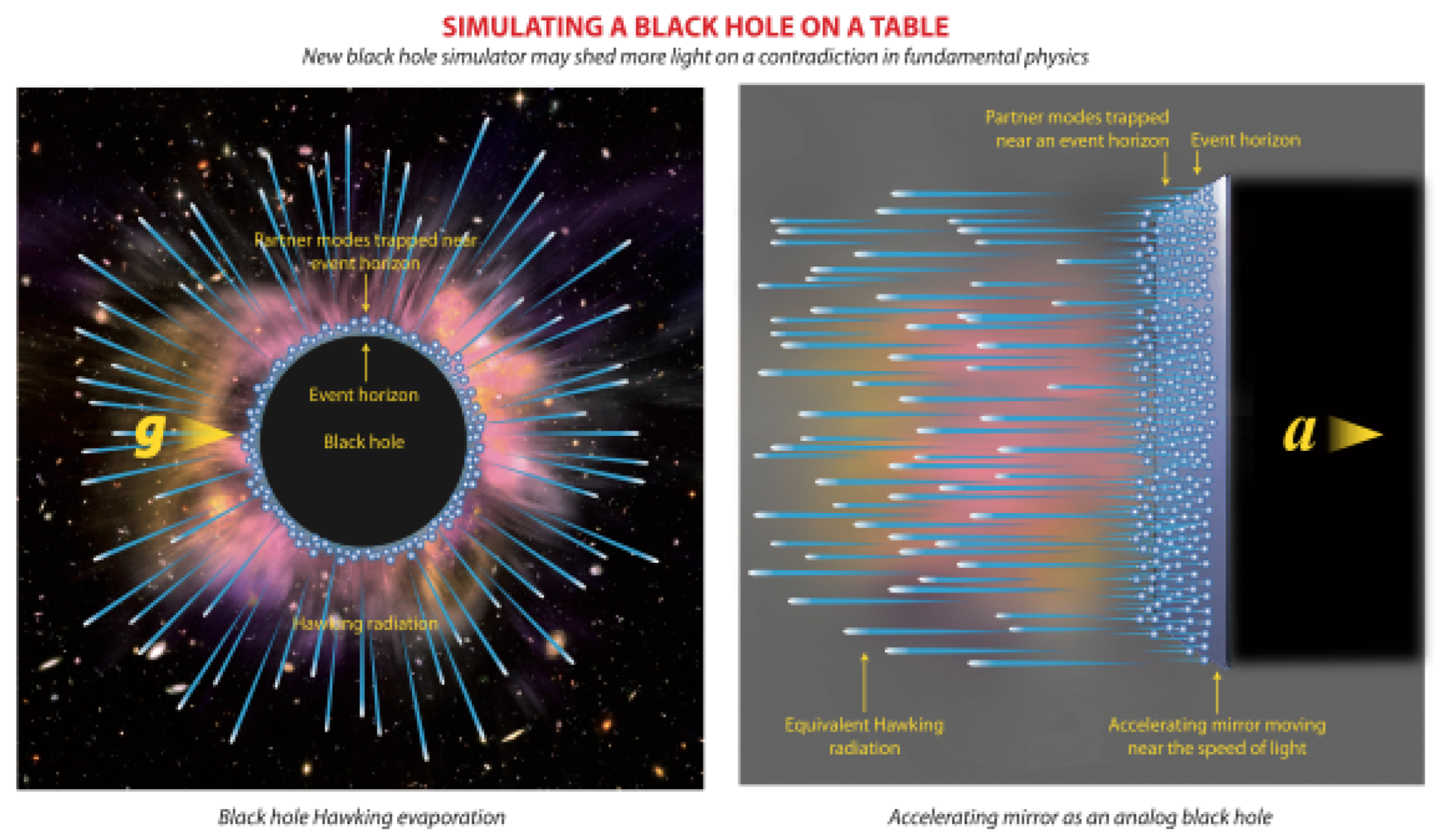
Figure 1 depicts the analogy between the Hawking radiation of a real BH (left) and that of an accelerating mirror (right). The fact that accelerating mirrors can also address the information loss paradox was first suggested by Wilczek [36]. As is well-known, the notion of black hole information loss is closely associated with quantum entanglement. In order to preserve the “black hole unitarity”, Wilczek argued that, based on the moving mirror model, in vacuum fluctuations, the 
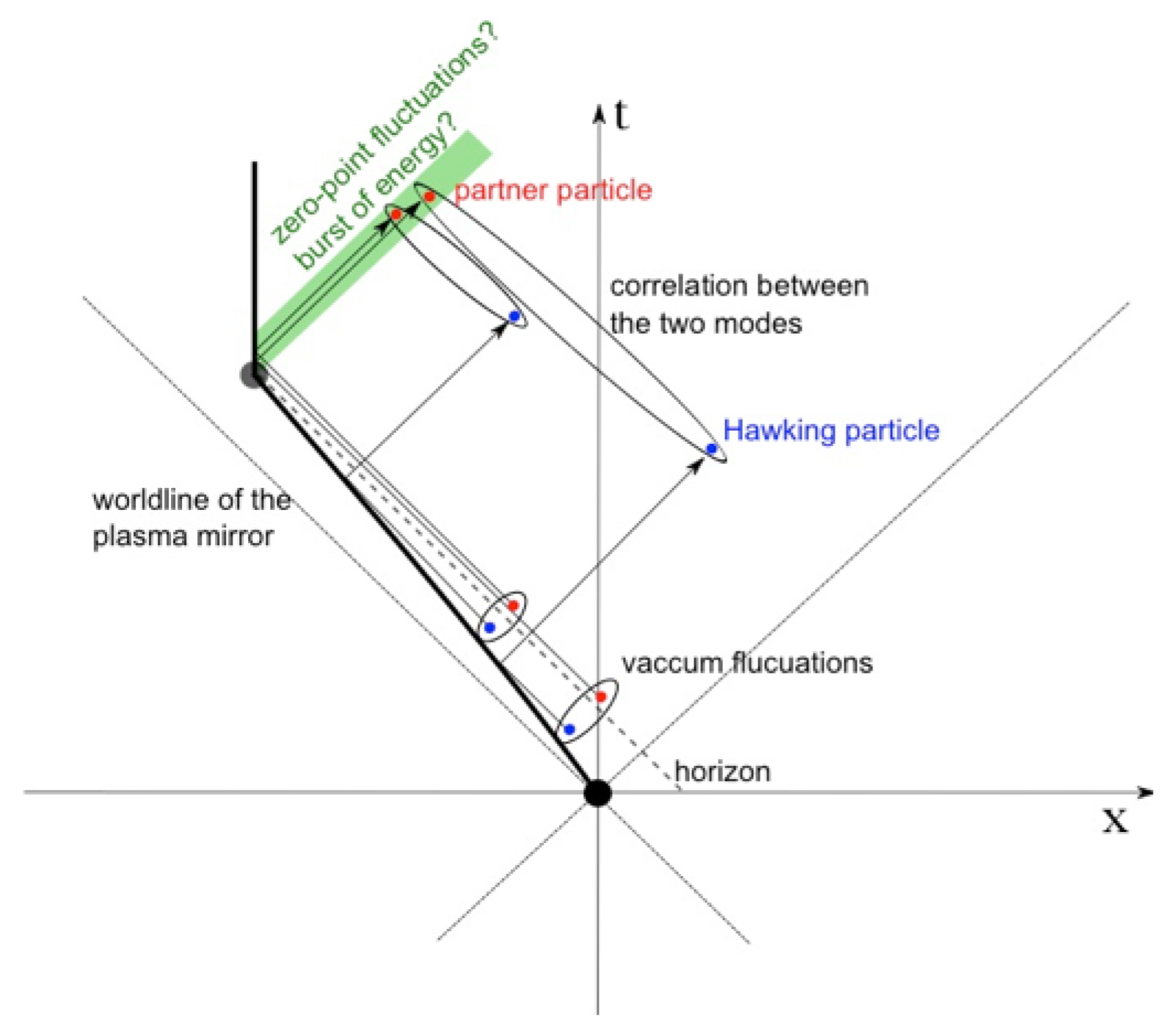
partner modes of the Hawking particles would be trapped by the horizon until the end of the evaporation, where they would be released and the initial pure state of a black hole would be recovered with essentially zero cost of energy. More recently, Hotta et al. [37] argued that the released partner modes are simply indistinguishable from the zero-point vacuum fluctuations. On the other hand, there is also the notion that these partner modes would be released in a burst of energy, for example, in the Bardeen model [38] (See Figure 2).
One common drawback in all analog black hole concepts involves setting up in a laboratory with flat spacetime (therefore, the standard quantum field theory is known to be valid); it is inevitable that any physical process, including analog black hole systems, must preserve the unitarity. Therefore, none of the proposed analog black holes can in principle prove the loss of information even if that is indeed so. The real issue is, therefore, not so much about whether the unitarity is preserved, but more about how it is preserved. That is, it is even more important to determine how the black hole information is retrieved. Does it follow the Page curve [39], a modified Page curve where the Page time is significantly shifted towards the late time [16], or alternative scenarios [40]? The measurement of the entanglement between the Hawking particles and the partner particles as well as the evolution of the entanglement entropy [41], should help to shed much light on the black hole information loss paradox. As pointed out by Chen and Yeom [41], different scenarios of black hole evolution can be tested by different mirror trajectories [42,43].

3. Accelerating Plasma Mirror via Density Gradient

As is well known, plasma wakefields [44,45] in the nonlinear regimes of plasma perturbations will blow out all intervening plasma electrons, leaving an “ion bubble” trailing behind the driving laser pulse or electron beam. Eventually, the expelled electrons will rush back and pile up with a singular density distribution. S. Bulanov et al. [28,29,30,31,34] suggested that such a highly nonlinear plasma wake could serve as a relativistically flying mirror where an optical frequency light, upon reflecting from the flying plasma mirror, would instantly blueshift to an X-ray. For a more in-depth understanding of the flying plasma mirror, please read [46,47] for an overview. To apply this flying plasma mirror concept to the investigation of black hole Hawking evaporation, one must make the plasma mirror accelerate.
In this regard, one important issue is the correspondence between the plasma density gradient and the mirror spacetime trajectory. In order to mimic the physics of the Hawking evaporation, the plasma mirror must undergo a non-trivial acceleration that gives rise to a spacetime trajectory that is black hole physics meaningful. Such black hole-relevant trajectories have been well studied theoretically in the past 40 years with a wealth of literature available. This, as proposed [25,26], can be realized by preparing the plasma target with a prescribed density gradient (See Figure 3 for a schematic drawing of the concept).

Mirror Trajectory and Plasma Density Correspondence

Two effects govern the acceleration of a plasma mirror [26]. One is the speeding up of the driving laser pulse as it traverses a plasma with a decreasing density, the so-called “down ramp”, due to the increase of the laser refractive index. The other is the change of the local plasma wavelength and, therefore, the length of the ion bubble, which enlarges the distance of the plasma mirror from the laser. The acceleration and, thus, the trajectory of a plasma mirror as a function of the local plasma density and its gradient was derived in [26], where both effects mentioned above are included. For the detailed derivations of the flying plasma mirror trajectory, the reader should consult Reference [26]. We caution that our theoretical description of the plasma mirror trajectory should be experimentally verified. In general,
x ¨ M c 2 = 1 ( 1 / 2 ) ω p 2 / ω 0 2 [ 1 ( 3 π / 2 ) c ω p / ω p 2 ] 3 × ω p 2 ω 0 2 ω p ω p + 3 π c 2 ω p ω p 2 2 ω p 2 ω p 3 ,
where x M is the position of the plasma mirror, x ¨ M is its second time derivative, ω 0 the laser frequency, ω p ( x ) = c 4 π r e n p ( x ) us the local plasma frequency, r e = e 2 / m e c 2 is the classical electron radius, and ω p ω p ( x ) / x . Our desire is to achieve the highest acceleration possible. To accomplish that, one should design the system in such a way that the denominator of Equation (1) is minimized.
A simple but well-motivated plasma density profile is the one that corresponds to the exponential trajectory investigated by Davies and Fulling [24,48], which is of special geometrical interest because it corresponds to a well-defined horizon [49]. Inspired by that, we consider the following plasma density variation along the direction of the laser propagation inside the plasma target with thickness L:
n p ( x ) = n p 0 ( a + b e x / D ) 2 , L x 0 ,
where n p 0 ( a + b ) 2 is the plasma density at x = 0 , D is the characteristic length of density variation. Accordingly, the plasma frequency varies as
ω p ( x ) = ω p 0 ( a + b e x / D ) , L x 0 ,
where ω p 0 = c 4 π r e n p 0 . In our conception, the time derivatives of the plasma frequency are induced through the spatial variation of the plasma density via the relation ω p ( x ) = c 4 π r e n p ( x ) . Thus,
ω p ( x ) = b D e x / D ω p 0 ,
ω p ( x ) = b D 2 e x / D ω p 0 .
Inserting these into Equation (1), we then have, for the constant-plus-exponential-squared distribution of Equation (2),
x ¨ M c 2 = 1 ( ω p 0 2 / 2 ω 0 2 ) ( a + b e x / D ) 2 [ 1 + ( 3 b / 4 ) ( λ p 0 / D ) e x / D / ( a + b e x / D ) 2 ] 3 × λ p 0 D b e x / D ( a + b e x / D ) { ω p 2 ω 0 2 1 λ p 0 + 3 4 D 1 a + b e x / D 2 b e x / D ( a + b e x / D ) 2 } .
PIC simulations of the laser–plasma interactions were performed based on the above plasma density profile [50]. The acceleration of the plasma mirror agrees well with the formula (See Figure 4).

4. Analog Hawking Temperature

There exists a wealth of literature on the vacuum fluctuating modes of quantum fields, their reflections from a flying mirror, and the analog “Hawking temperature” of such a flying mirror as an analog black hole [49]. In general, such analog Hawking temperature depends on the actual mirror trajectory. According to Reference [26],
0 t c ¯ d t = x M 0 d x 1 + 3 b λ p 0 4 D e x / D ( a + b e x / D ) 2 , x 0 ,
where c ¯ = η c = ( 1 ω p 2 / 2 ω 0 2 ) c is the speed of light in the plasma medium, which is position dependent. In our conception [25], the plasma target thickness is supposed to be much larger than the characteristic scale of the density variation, i.e., L D . In this situation, it is safe to extend the integration to x M (and t ). Taking this approximation, we find
x M ( t ) = η a c t A e η a c t / D + A , t ,
where η a = 1 a 2 ω p 0 2 / 2 ω 0 2 and A = η a D [ a b ( ω p 0 2 / ω 0 2 ) ( 3 b / 4 a 2 ) ( λ p 0 / D ) ] . This is identical to the Davies–Fulling trajectory, i.e., Equation (4.51) of Reference [49],
z ( t ) t A e 2 κ t + B , t ,
where A , B , κ are positive constants and c 1 .
Transcribing the x M ( t ) coordinates to the ( u , v ) coordinates, where u = η a c t x M ( t ) and v = η a c t + x M ( t ) , we see that only null rays with v < A can be reflected. All rays with v > A will pass undisturbed. The ray v = A , therefore, acts as an effective horizon [49]. Following the standard recipe [49], we obtain the Wightman function as
D + ( u , v ; u , v ) = 1 4 π ln [ 2 A e 2 η a c ( t + t ) / 2 D × sinh ( η a c Δ t / 2 D ) ] ,
where Δ t = t t = Δ u / 2 η a c in the t limit. The constant factors in the argument of the log function in the above equation do not contribute to the nontrivial part of the physics. Note that in our notation, t is the time when the ray hits the mirror. Let us denote the observation time and position by T and X. Then u = η a c T X = η a c t x M . For large t, u = η a c T X = 2 η a c t A . This leads to Δ u = 2 η a c Δ t = η a c Δ T for a static mirror at X = const . Integrating over T and T , we then have, in the asymptotic limit of t , t ,
D + ( u , v ; u , v ) = 1 4 π ln sinh ( η a c Δ t / 2 D ) .
This leads to the response function (of the particle detector) per unit of time with the form
F ( E ) / unit time = 1 E 1 ( e E / k B T H 1 ) ,
where the analog Hawking temperature of the mirror measured by a stationary particle detector is
k B T H = c 4 π η a D .
Here, k B is the Boltzmann constant. It is interesting to note that the analog Hawking temperature associated with our constant-plus-exponential-squared density profile depends strongly on the characteristic length D and only weakly on the plasma density (through η a ). This points to the possibility of employing gaseous instead of solid plasma targets, which would greatly simplify our proposed experiment.

5. Conceptual Design

The original experimental concept proposed by Chen and Mourou [25] invoked a two-plasma-target approach, where the first plasma target converts an optical laser into an X-ray pulse through the flying plasma mirror mechanism. The converted X-ray pulse then impinges on a nano-thin-film that is fabricated with a graded density in different layers. This design has the advantage of having a solid-state density, providing a higher plasma frequency, which is proportional to the square root of the plasma density and, therefore, a higher density gradient for maximizing the Hawking temperature. On the other hand, the drawbacks of this concept are multiple. First, the typical conversion efficiency of flying plasma mirrors is ∼ 10 5 , rendering it difficult for the converted X-ray pulse to remain in the nonlinear regime. Second, the solid plasma target would induce extra backgrounds, which are linearly proportional to the target density.
In 2020, Chen and Mourou proposed a second design concept [
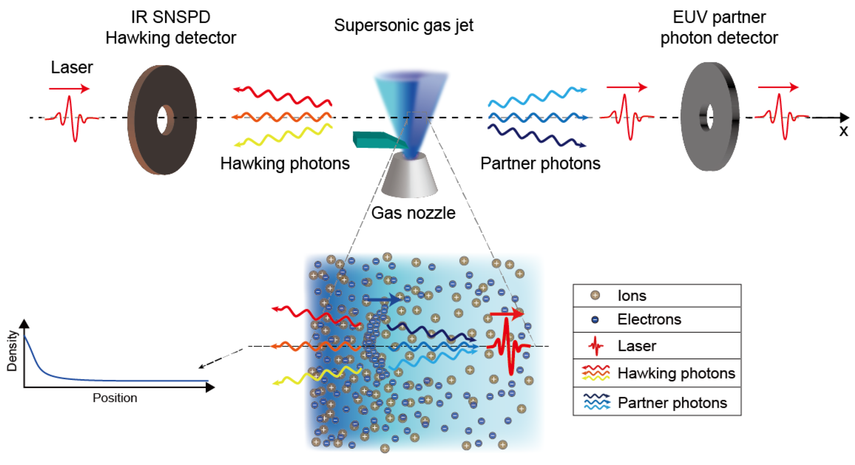
26], where the conversion of optical laser to X-ray was no longer needed and, thus, the first plasma target was removed, and the nano-thin-film solid plasma target was replaced by a supersonic gas jet. This largely simplifies the design and the technical challenges. Figure 5 shows a schematic conceptual design of the single-target, optical laser approach. The key components now reduce to a supersonic gas jet with a graded density profile and a superconducting nanowire single-photon Hawking detector, the R&D progress of which will be described in later sections.
In our design of the AnaBHEL experiment, we assume the driving laser has the frequency ω 0 = 3.5 × 10 15 s 1 and the wavelength λ p = 540 nm . For the plasma target, we set a = b = 1 in Equation (2) so that n p ( x ) = n p 0 ( 1 + e x / D ) 2 , and we assume n p ( x = 0 ) = 1.0 × 10 17 cm 3 = 4 n p 0 . The corresponding plasma frequency is ω p 0 = 0.9 × 10 13 s 1 and the plasma wavelength λ p 0 = 200 μ m . Next, we design the plasma target density profile. Since our formula is not constrained by the adiabatic condition, we are allowed to choose a minute characteristic length D = 0.5 μ m . Then we find
k B T H 3.1 × 10 2 eV ,
which corresponds to a characteristic Hawking radiation frequency ω H 4.8 × 10 13 s 1 > ω p 0 . Thus, the Hawking photons can propagate through and out of the plasma for detection.

6. Hawking Photon Yield

Among the proposed models, the physics of flying/moving mirrors is perhaps the one closest to that of real black holes, since in both cases the radiation originated from vacuum fluctuations. The essence of the Hawking radiation lies in the gravitational redshift of the field modes’ phases. Since the key is the phase shift, various analog models or experimental proposals attempt to generate the same phase shift as that of the Hawking radiation but now in flat spacetime, i.e., laboratory. Indeed, in the flying mirror model, the gravitational redshift is mimicked by the Doppler redshift.
Due to the spherically symmetric nature of typical black hole spacetimes, the spherical coordinate origin is effectively a perfectly reflecting point mirror and the corresponding Hawking radiation is expected to be emitted radially, hence the situation is effectively (1+1)-dimensional and, thus, most of the flying mirror literature only considers a real perfectly reflecting point mirror in (1+1)-dimensional flat spacetime. Nevertheless, in the laboratory, the spacetime is (1+3)-dimensional. In addition, our proposed relativistic flying mirror generated through laser–plasma interaction has a low reflectivity [26] and a finite transverse/longitudinal size; therefore, it is necessary to take these practical effects into consideration to estimate the particle production yield.
The standard treatment in the flying mirror model [24,48,49,51] considers a real scalar field in (1+1)D flat spacetime subjected to a single, relativistic, time-dependent Dirichlet boundary condition in space to represent a relativistic perfectly reflecting point mirror. Since the boundary condition is externally provided, the breakdown of Poincaré invariance leads to the possibility of spontaneous particle creations following quantum field theory.
The generalization of this standard calculation to a flying plasma mirror with a finite reflectivity in n-dimensional flat spacetime can be made by starting with the action functional [52]:
S μ [ ϕ ] = 1 2 d n x μ ϕ ( x ) μ ϕ ( x ) μ 2 d n x V ( x ) ϕ 2 ( x ) ,
where natural units are employed, μ = 4 π n s α / m e is the coupling constant with dimension of mass, α = 1 / 137 is the fine structure constant, n s is the surface density of the electrons on the mirror, and
V ( x ) = γ 1 ( t ) H ( x ) f ( x x M ( t ) ) ,
encodes the mirror’s trajectory x M ( t ) , longitudinal/transverse distribution H / f , and the Lorentz factor γ .
Solving the equation of motion for ϕ with the in-mode/out-mode boundary conditions in (1+1) dimensions, one finds (assuming the field to be in the in-vacuum state 0 ; in with the mirror flying to the negative x-direction) the created particles (due to the field mode reflected to the mirror’s right to have the frequency spectrum) [53,54,55,56]:
N = 0 d ω 0 d ω β ω ω 2 ,
where
β ω ω = ω 2 π ω ω d u R ω ( u ) e i ω p ( u ) i ω u ,
and ω / ω is the incident/emitted plane wave mode’s frequency, R is the mirror’s reflectivity, u = t x M ( t ) , and p ( u ) = t + x M ( t ) is the phase shift/ray-tracing function induced upon reflection off the receding mirror. From Equation (18), one sees that for a given trajectory x M , the spectrum would be different depending on the reflectivity.
A simple model that mimics the formation and evaporation of a Schwarzschild black hole is the collapse of a spherical null shell. In this scenario, the relevant ray-tracing function is
u = p ( u ) 1 κ ln κ ( v H p ( u ) ) ,
where κ > 0 is the black hole’s surface gravity, and v H is the past event horizon, which is conventionally set to zero. For field modes propagating in the vicinity of v H (late time), u κ 1 ln κ p ( u ) , and ω ω (extreme gravitational/Doppler redshift), one obtains
β ω ω 2 1 2 π κ ω 1 e ω / T H 1 ,
for a perfectly reflecting point mirror, and
β ω ω 2 μ 2 8 π κ ω ω 2 1 e ω / T H + 1 ,
for a semi-transparent point mirror, where T H = κ / ( 2 π ) is the analog Hawking temperature. In general, the accelerating mirror radiates along the entire worldline, but only those radiated in the late time are relevant to the analog Hawking radiation. In particular, the spectrum Equation (20) for a perfectly reflecting point mirror is in exact accordance with the Hawking radiation emitted by a Schwarzschild black hole. Although a semi-transparent point mirror possesses a different spectrum due to the time-dependent and frequency-dependent reflectivity, it nevertheless has the same temperature as that of a perfectly reflecting point mirror.
As previously mentioned, practical considerations in the laboratory force us to work in (1+3)-dimensional spacetime and a mirror with some kind of longitudinal/transverse distribution. In the case of a semi-transparent mirror, it is possible to find the corresponding analytic spectrum through a perturbative approach. The result is
d N d 3 k = d 3 p β kp 2 ,
where [56]
β kp k , p ; out | 0 ; in 0 ; out | 0 ; in F ( k , p ) × i μ 16 π 3 ω k ω p × d t γ 1 ( t ) e i ( ω k + ω p ) t i ( k x p x ) x M ( t ) ,
where ω p / ω k is the incident/emitted plane wave mode frequency, respectively, and
F ( k , p ) = d 2 x H ( x ) e i ( k + p ) · x × d ζ f ( ζ ) e i ( k x p x ) ζ , ζ = x x M ( t ) ,
is the form factor due to the mirror’s longitudinal and transverse geometry, which is independent of the mirror’s motion and reflectivity.
According to particle-in-cell (PIC) simulations [50], a mirror of square-root-Lorentzian density distribution and a finite transverse area can generate a good-quality mirror. Thus, we shall consider the case:
V ( x ) = γ 1 ( t ) Θ ( y + L / 2 ) Θ ( y L / 2 ) ( x x M ( t ) ) 2 + W 2 × Θ ( z + L / 2 ) Θ ( z L / 2 ) ,
where W is the half-width at half maximum of the square-root-Lorentzian distribution and L × L is the transverse area. In addition, according to the plasma density profile designed in Reference [26], the mirror follows the trajectory:
t ( x M ) = x M v , v 1 , 0 x M < , x M + 3 π 2 ω p 0 ( 1 + b ) 1 + b 1 + b e x M / D 1 , else ,
where { ω p 0 , b , D } are positive plasma mirror parameters and time t is written as a function of the trajectory x M . This trajectory is designed such that it approximates the black hole-relevant trajectory: u κ 1 ln κ p ( u ) either (i) at the late-time ( t ) for any value of b, or (ii) in a near-uniform plasma background ( b 1 ) during the entire accelerating phase. In either case, the spectrum relevant for the analog Hawking radiation is
d N d ω k d Ω μ 2 8 π κ ω k e ω k / T eff ( θ k ) + 1 d p x F L ( k , P ) F W ( k x , p x ) p x 2 ,
where T eff ( θ k ) = κ / [ ( 1 + cos θ k ) π ] is the effective temperature, κ = 1 / ( 2 D ) , and F L / W are complicated form factors due to the mirror’s transverse/longitudinal distributions given in Reference [56]. Notice that the form factor F L leads to diffraction, whereas F W may enhance the production rate.
Using the PIC simulation parameter values: μ = 0.096 eV, κ = 0.2 eV ( D = 0.5 μ m ), ω p 0 = 0.006 eV, W = 0.0074 eV 1 (1.5 nm), L = 254 eV 1 (50 μ m ), and b = 1 , the resulting analog Hawking temperature is T eff 0.031 
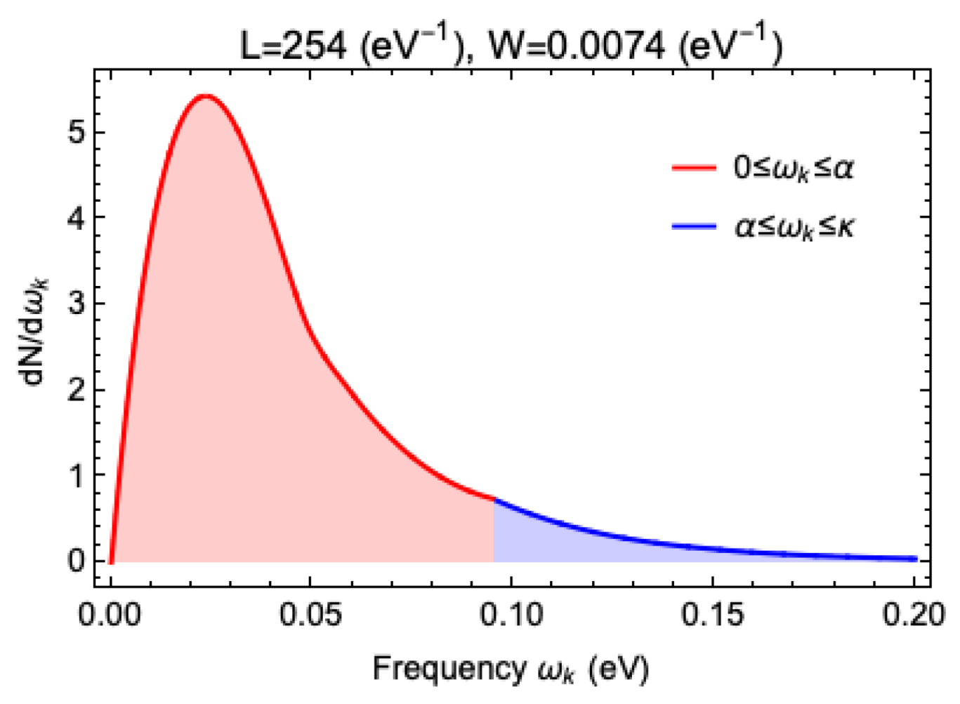
eV (369 K) in the far infrared regime and the number of produced analog Hawking particles per laser crossing is
N 0 κ d ω k d Ω d N d ω k d Ω = ( 0.27 + 0.02 ) ,
where 0.27 and 0.02 correspond to the red and the blue areas in Figure 6, respectively.
Assuming a petawatt-class laser, such as that in the Apollon Laser Facility in Saclay, France, which can provide 1 laser shot per minute and 8 h of operation time per day, a 20-day experiment with a 100% detector efficiency would give the total yield of events as
N detect = ( 1 × 60 × 8 × 20 ) × 1 × N 3000 .
It should be reminded that this value is highly idealized. Fluctuations of the physical parameters, especially that of the characteristic length of the density gradient, D, which we have not yet measured, would impact the expected Hawking photon yield.

7. Supersonic Gas Jet

As estimated in Reference [25], the gradient of the electron number density required for the experiment is ∼ 10 20 / cm 3 / cm , which is attainable with a supersonic gas jet. There are several methods proposed in the literature, such as a shock wave generated induced by a laser that propagates perpendicular to the gas jet [57,58], and a supersonic gas flow impinged by a thin blade [59,60]. The estimated gradients of the electron number densities reached by different groups in [57,59,60] are summarized in Table 1. It is clear that, in principle, both methods can provide gradients that satisfy our requirement. As our first attempt, we chose the latter method for its simplicity.
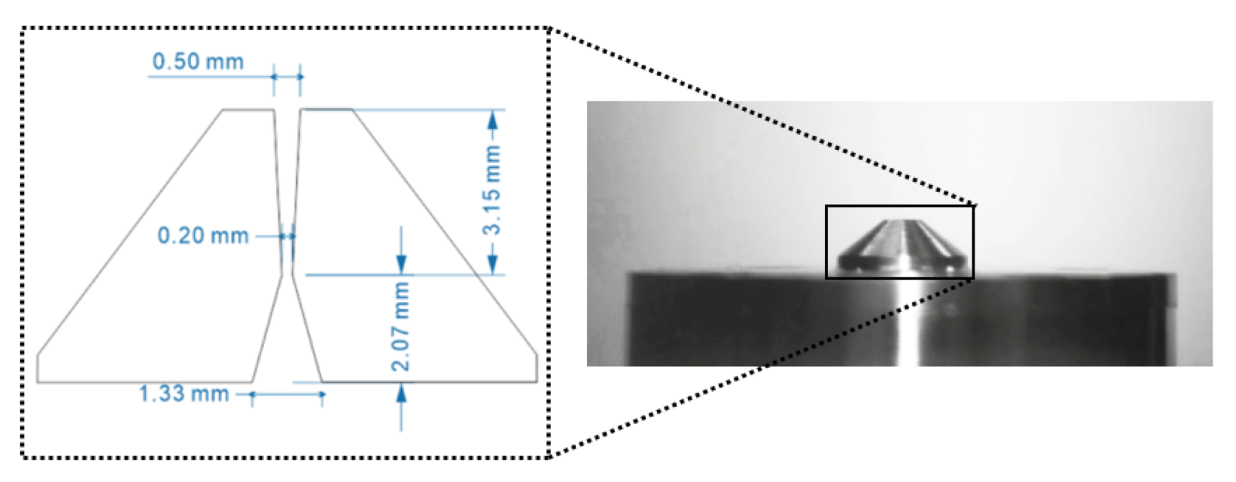
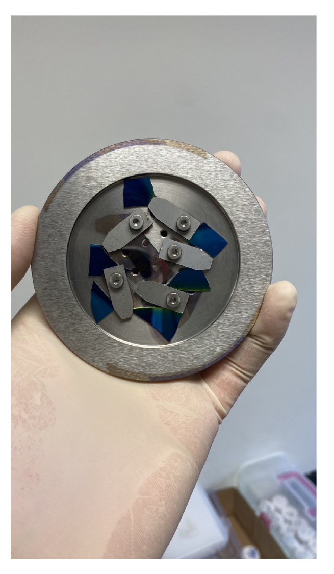
The supersonic gas jet can be realized by passing high-pressure gas through the de Laval nozzle, which is also known as the converging-diverging nozzle. The gas flow will reach sonic speed at the throat of the nozzle and then be accelerated in the diverging section to reach supersonic speed. Based on the design of the nozzle in [61], we produce our own nozzle to generate supersonic gas flow. Figure 7 shows the inner geometry and the image of the nozzle we built. The nozzle is connected to the tank of an air compressor that can provide air with pressure up to 8 atm. An electrically controlled valve is placed between the nozzle and the tank to control the flow.
There are several techniques to quantitatively characterize the density of a supersonic gas jet, including interferometry and shadowgraphy [62,63,64,65], tomography [62,66,67], planar laser-induced fluorescence (PLIF) [60,68,69], Schlieren optics [70,71] (more references can be found in [
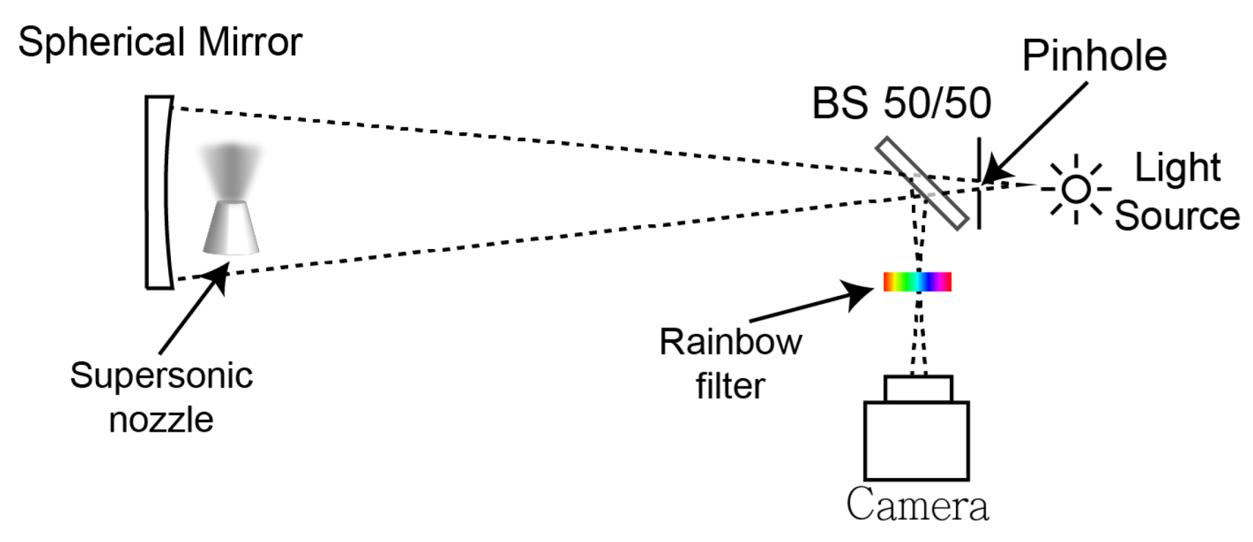
71]). As the first step, we built a Schlieren imaging system in the lab for the jet characterization. Our Schlieren optics is equipped with a rainbow filter, which allows for the visualization of the gas jet as well as quantitative analysis of its refractive index. Figure 8 demonstrates the schematic diagram of our system.
The principle behind the Schlieren optics is that the variation of the refractive index would diffract light. A rainbow filter that intercepts the diffracted light then provides information that would quantitatively determine the diffraction angle according to the color codes. The imaging system is calibrated with a plano-convex lens, whose refractive index is known. In this way, the map of the refractive index gradient, which is directly related to the gas density gradient, can be obtained.
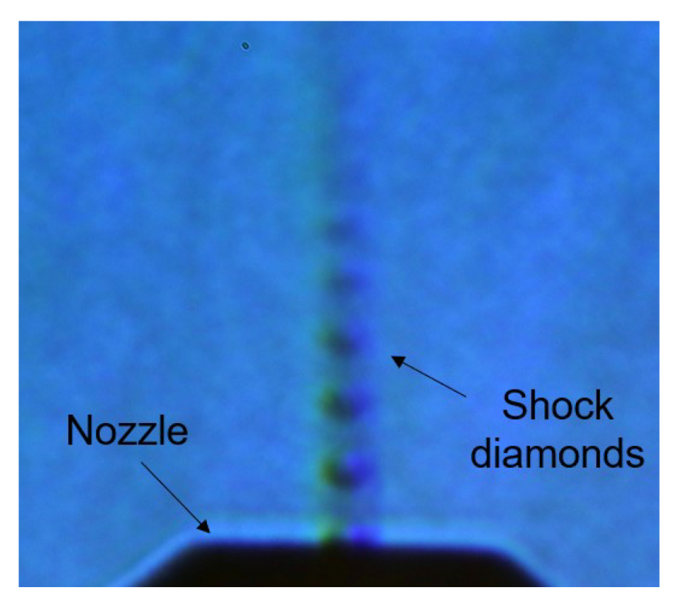
Figure 9 shows the image using our Schlieren optics. The figure shows the supersonic jet produced by the nozzle. The so-called “shock diamonds” are clearly demonstrated, which is an indicator of the jet propagating with supersonic speed in the atmosphere.
The design of the nozzle is verified by comparing the shock diamond structure from the data with the computational fluid dynamic (CFD) simulation result. The 3D fluid simulation was performed with OpenFOAM code. In the simulation, a compressible Navier–Stokes flow solver, rhoCentralFoam [72], is used to study the behavior of the supersonic jet.
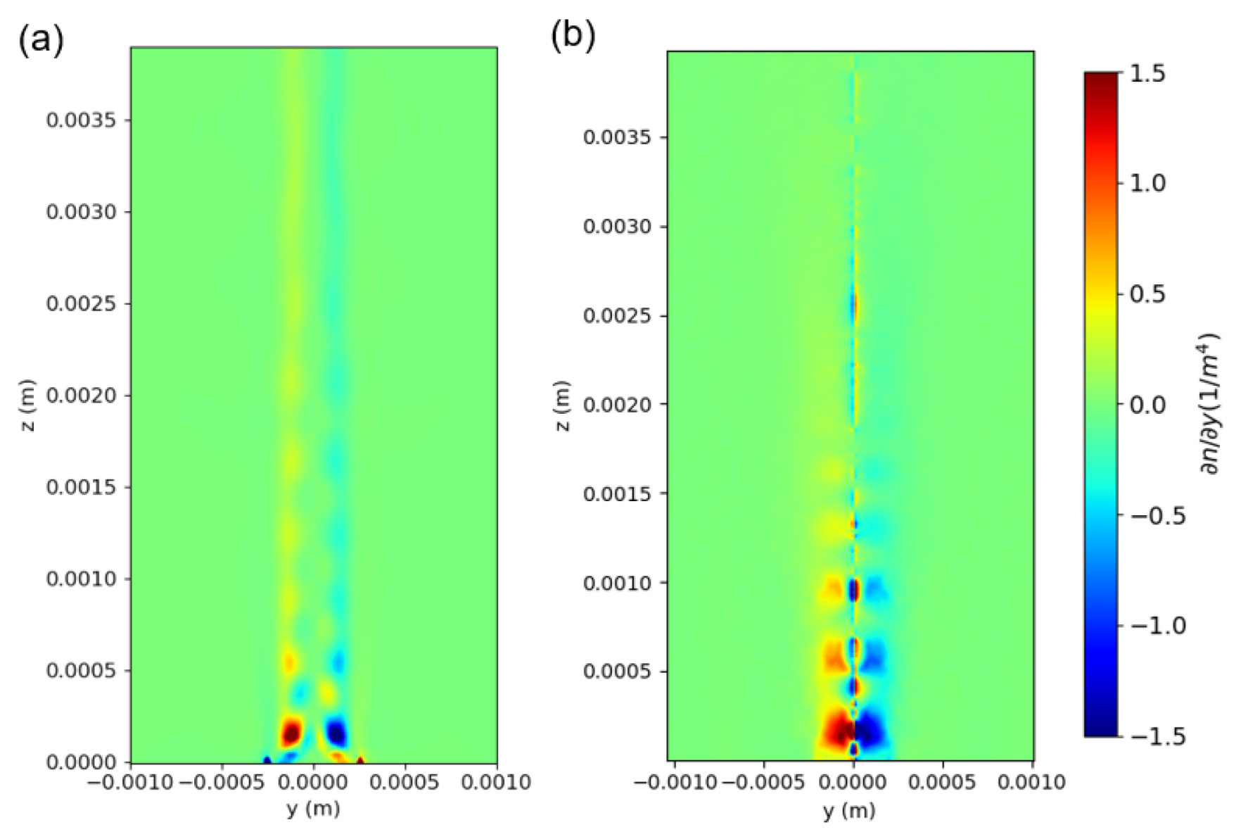
With the conventional Abel inversion technique, the gradient of the refractive index was reconstructed and compared with the simulation result in 
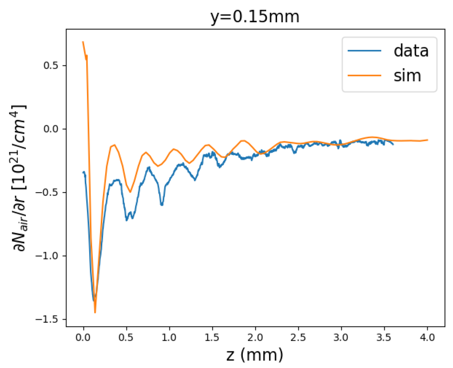
Figure 10. Line profiles at different horizontal positions, y, relative to the axial center of the gas jet are shown in Figure 11. We found the positions of several peaks in the data agree reasonably with simulation results. This implies the behavior of our self-made supersonic nozzle is as expected and our Schlieren optics can characterize the profile of the supersonic jet. Further improvement is ongoing to obtain results with higher accuracy.

8. Superconducting Nanowire Single-Photon Hawking Detector

Observing the Hawking photons is the main goal and one of the major challenges of the planned AnaBHEL experiment. There is probably no single technology that satisfies all requirements. The detector must be a single photon detector, with efficiency close to 100%. The desired Hawking photon sensitivity wavelength range should be from 10 μ m to 100 μ m. A second detector design is required for the forward-moving partner photon with sensitivity at the UV (1–100 nm). The low expected signal yield and the potentially large asynchronous thermal and plasma-induced backgrounds set stringent detector timing requirements (to picosecond level or better). Since within the data acquisition timing window accidental coincidences may still be present, single photon pair polarization measurement will be required in order to unambiguously tag the pair as Hawking and partner photons. In addition to the above requirements, the detector should have a very fast recovery to avoid photon pile-up, a very low dark current rate (DCR), and the ability to cover relatively large areas.
Superconducting nanowire single-photon detectors (SNSPDs) satisfy most of the above requirements [73]. Thin superconducting films (∼10 nm) from materials such as NbN and WSi are sputtered on substrates. Subsequently, electron nanolithography is used to etch narrow wire structures (50–100 nm wide). The detector operates at a temperature below the Curie temperature T C at an appropriate bias current that maximizes efficiency. Additional cavity structures are needed in order to bring the efficiency close to 100%.
The intrinsic time jitter of SNSPDs is ∼1 ps. Recently, time jitters using short straight nanowires and are found to be <3 ps for NbN [74] and 4.8 ps for WSi wires [75]. Thanks to their short reset time, these devices exhibit very high count rates at the level of hundreds of MHz. Although the expected Hawking photon yield is low, such a fast recovery detector reduces dramatically the probability of photon pileup (multiple counts in the same time window). The dark count rate (DCR) is extremely low at the level of one count for a period of hours, depending on the operating temperature and the bias current.
Typical SNSPD designs relevant to AnaBHEL are based on a superconducting nanowire patterned from a thin film of thickness between 5 and 10 nm. The most common nanowire design follows a meandering structure geometry. However, in our case, we need to consider specific structures that have sensitivity to polarization. SNSPDs are DC-biased with operation currents close to their critical currents so that efficiency is maximized. As discussed in [73], the detection process is divided into the following steps: (I) Photon absorption; (II) Creation of quasiparticles and phonons combined with their diffusion; (III) Emergence of a non-superconducting nanowire segment; (IV) Redirection of the bias current in readout circuitry, leading to a voltage pulse; and (V) detector recovery.
During step (II), the impinging near-IR photon photo-excites an electron (the relaxation of which leads to the formation of a cloud of quasiparticles and phonons). An instability of the superconducting state emerges due to the quasiparticle cloud, which results in the reduction of the effective critical current density and a part of the nanowire experiences a transition to the non-superconducting state (III). The occurrence of a normal-conducting hot spot in the nanowire can lead to the detection of the photon event as the current flowing through the bias resistor (bias current) is re-directed. Due to internal Joule heating, the resistive domain of the nanowire keeps growing, which leads to increased resistance at the level of k Ω . This significant non-zero resistivity causes the redirection of the bias current from the nanowire to the readout electronics (IV). Finally, the resistive domain is cooled down and the superconductivity is restored, bringing the nanowire back to its initial state (V).
Specific requirements of the AnaBHEL experiment photon sensors are summarized in Table 2 (first row). Realistic operational parameters and performance for typical SNSPD materials are also presented.
In most applications, SNSPDs are coupled to fibers with a typical operation wavelength at the telecom window (1550 nm). AnaBHEL is an open-air experiment with a tight requirement of operation at mid to far infrared ( λ > 10 μ m) regime. As reported in [76,77], significant progress has been made for open-air longer wavelength operating SNSPDs. To achieve sensitivity for wavelengths longer than 10 μ m, materials of lower Curie temperatures must be used. WSi is an example of such material. However, further R&D on other materials is needed.
In addition to efficiency, successful detection of the Hawking and partner photons in AnaBHEL requires good detector acceptance in both the forward and backward parts of the experimental apparatus. A single-pixel SNSPD covers a very small active area of the order of 10 × 10 μ m 2 . To maximize photon acceptance, a 1 × 1 mm 2 pixel array would be preferred. This kilopixel array has already been produced [78] and used in exoplanet transit spectroscopy in the mid-infrared regime.

Hawking Photon Sensor Fabrication and Characterization

In 2021, a R&D program was initiated in Taiwan to develop photon sensors for Hawking photon detection. Academia Sinica, NTU, and NCU groups are currently sharing equipment and laboratories for the fabrication and testing of prototype SNSPDs, the preferred technology for Hawking-photon sensors.
We have been producing NbN films of 10 nm thickness using the Academia Sinica magnetron sputtering machine shown in Figure 12 (Kao Duen Technology, Model: KD-UHV, N-11L17). The films grown on two different substrates, MgO and distributes Bragg reflector (DBR), were used. The films were sputtered at UHV pressure of 10 9 Torr. Sample NbN films on a sample holder are shown in Figure 13.
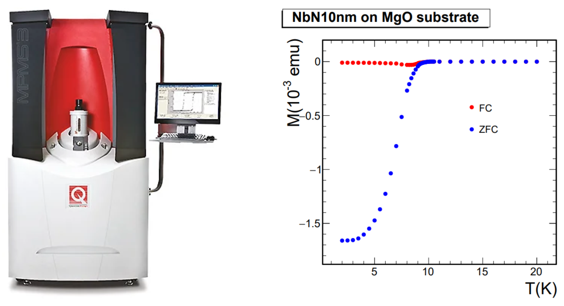
The superconducting transition properties of the NbN films have been determined using magnetic susceptibility measurements with a SQUID, as well as electric resistivity measurements. In the left side of Figure 14, the MPMS3 SQUID magnetometer is used to measure the magnetic susceptibility of the NbN samples grown on MgO. On the right side of the same figure, the superconducting transition is shown as the material becomes diamagnetic. A 4 mm × 4 mm NbN sample was placed in the SQUID and its magnetic susceptibility was measured in the temperature range of 2–20K in steps as small as 0.1K per step as it approached the Curie temperature T C .
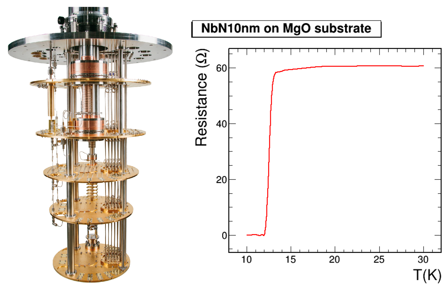
Electric resistivity measurements were performed with the Triton 500 cryogenics system set up by the NTU-CCMS group, shown in Figure 15 (left). A superconducting transition measurement for a NbN film sample is shown in Figure 15 (right). Samples of 3 × 3 mm 2 sizes were prepared and glued on a sample holder with CMR-direct GE varnish. The sample was wire-bonded to readout pads on the sample holder using aluminum wires. The holder carried 20 readout pads, allowing us to perform more than the minimum requirement of 4 bonds. In this way, we ensured that we still had connectivity in case some bonds broke in very low operating temperatures. The resistivity was first measured at room temperature to check for possible oxidation or defects in the film growth process, and to test the connectivity of the wire bonds.
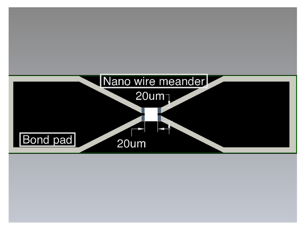
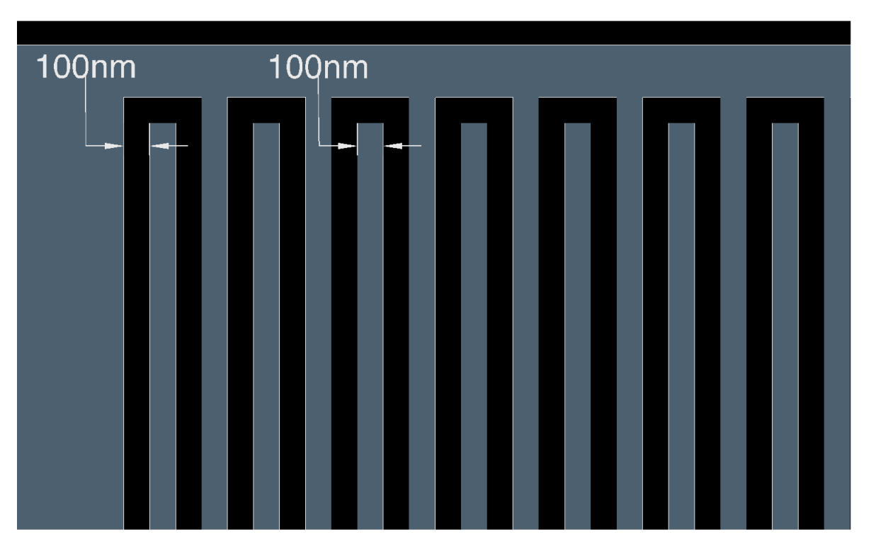
After the successful characterization of the NbN-sample superconducting properties, we proceed with the production of prototype nanowire sensors. The performance requirements for the Hawking photon sensors necessitate the use of the electron beam lithography (EBL) for the etching of nanowires from the NbN films. Currently, nanowire prototypes of different widths and lengths are under design. The baseline design using an autoCAD drawing of a 20 × 20 μ m 2 sensing area, with a nanowire with a width of 100 nm and a pitch of 100 nm, is shown in Figure 16 and the zoom-in is shown in Figure 17.
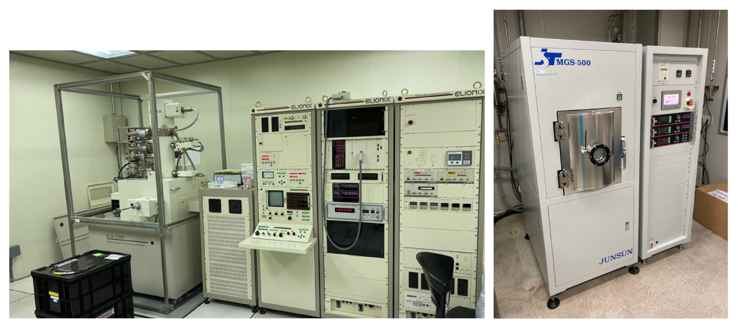
The SNSPD sensor prototypes are produced by the EBL, ELS-7000 ELIONIX, machine located in the Academia Sinica laboratories, as shown in Figure 18 (Left). Mean while, our AnaBHEL Collaboration has purchased a Junsun Tech MGS-500 sputtering machine installed at the NEMS center of NTU Figure 18 (Right), which will be fully utilized.
In order to maximize the single photon detection efficiency, various structures such as cavities or Bragg reflectors can be utilized. As part of the ongoing R&D, distributed Bragg reflectors (DBR) have been grown in the NTU MEMS facility. The measured reflectivity of a DBR for a sensor sensitive at 1550 nm is shown in Figure 19. The good agreement with a finite-difference time-domain method (FDTD) simulation of the structure, gives us the confidence to proceed with new cavity designs optimal for longer wavelengths.
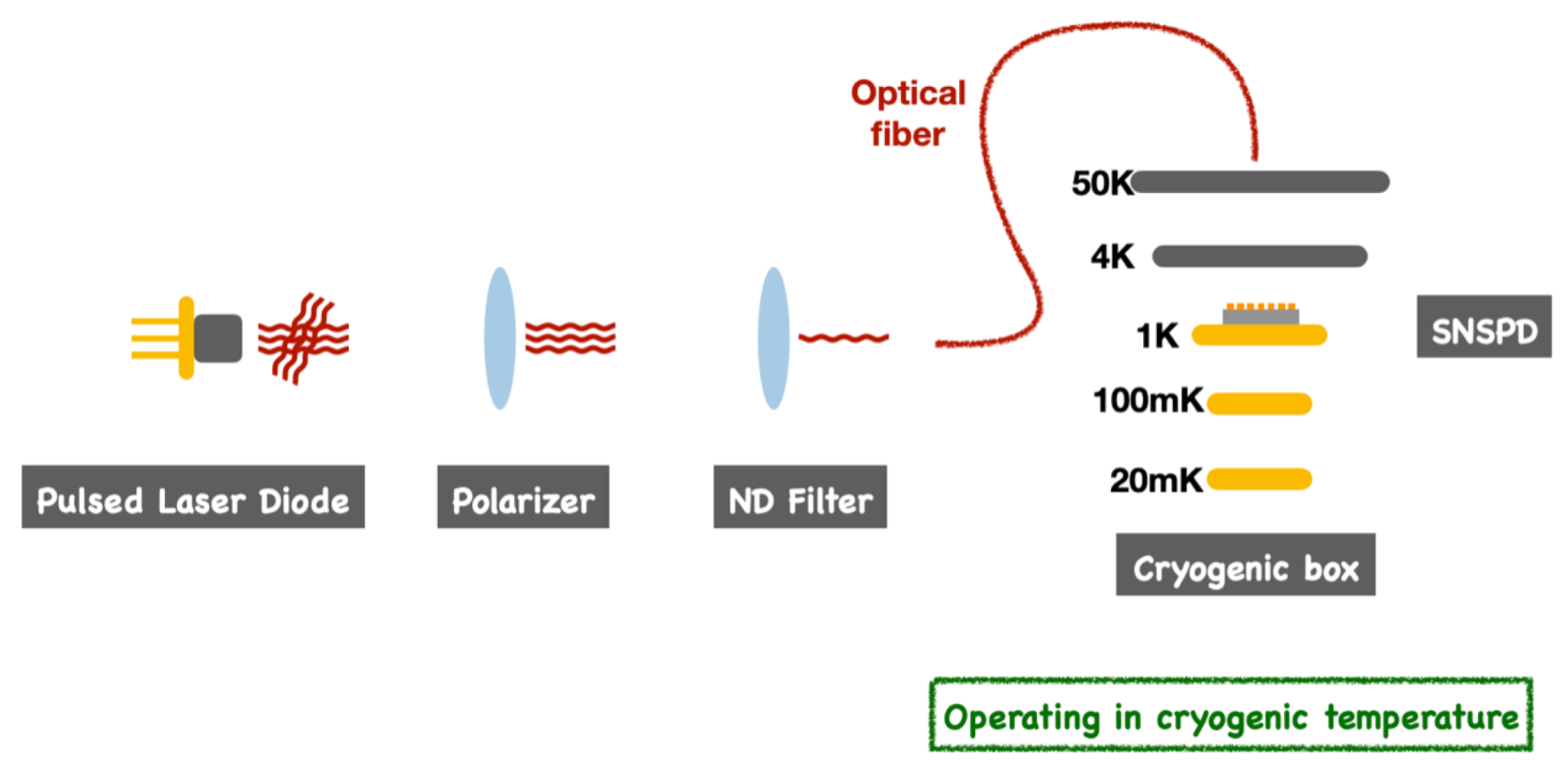
We are currently in the process of setting up a system test bench to characterize the Hawking sensors, using single photons at the infrared. The setup includes a SPAD commercial sensor for single photon calibration shown in Figure 20. We plan to first verify the sensor operation at 1550 nm where most commercially available SNSPDs operate, as shown in 
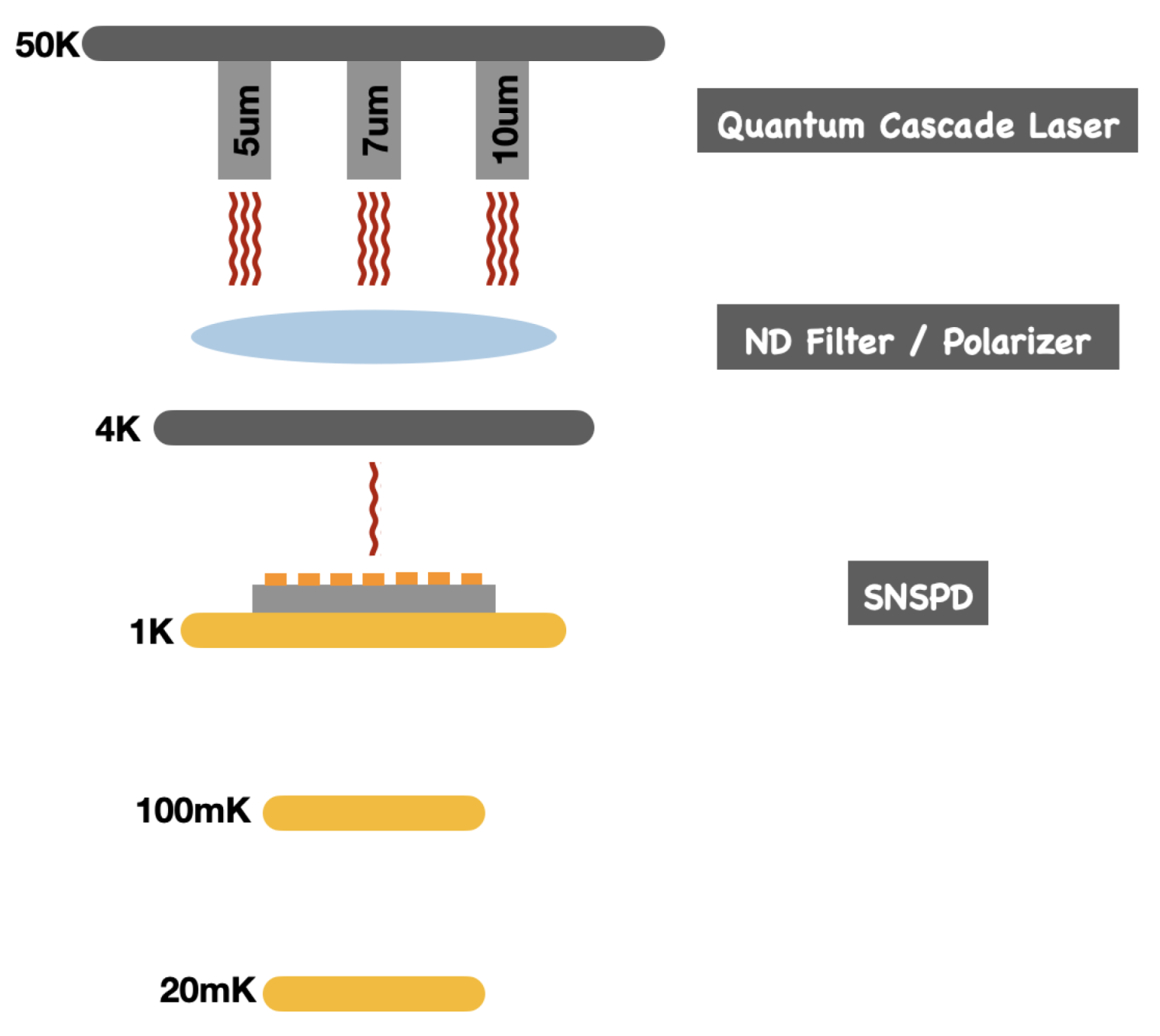
Figure 21. Finally, the sensors will be tested at longer wavelengths relevant to the AnaBHEL experiment shown in Figure 22.

9. Experimental Backgrounds

The propagation of the high-intensity laser through a plasma target would necessarily induce background photons that would compete against the rare Hawking signals. The plasma electrons perturbed by the propagating laser would execute non-trivial motions and can therefore emit photons. In addition, they can interact with the electromagnetic fields induced by the laser and charged particles, and also with the plasma ions through scatterings.
The radiations induced from interactions between the electrons and the background ions can be categorized into Thomson/Compton scattering and Bremsstrahlung. These processes have long been well studied and the radiation so induced can be estimated when the electron trajectories are given.
There is also the possibility of radiation caused by electron acceleration. The analytic solution for plasma accelerating in the blowout regime of plasma wakefield excitations has been studied by Stupakov [79], where it was shown that there are not only accelerated plasma inside the bubble but also charged particles that oscillate along the boundary of the plasma bubble. The work [79] was for the case of the plasma wakefield accelerator (PWFA) [45], but the method can also be applied to a laser wakefield accelerator (LWFA) [44], which is the basis of our flying plasma mirror. Thus we also expect to have the same type of electron motions that are oscillating around the plasma bubble. These electrons in the plasma wakefields perform a figure-8 motion in the plasma, and they can emit low-energy photons through synchrotron radiation. These photons are propagating in the direction parallel to the laser, which could affect the observation of the partner photons downstream. Therefore, we should study these electrons carefully.
In the following, we categorize the trajectories of the plasma electrons obtained from simulations by using a machine learning-based technique. We classify the electrons into several categories, according to their characteristic motions. After this classification, we are able to identify the leading radiation processes for the electrons and evaluate the radiation spectrum. We use SMILEI [80] for particle-in-cell (PIC) simulations and python and the scikit-learn library [81] for the clustering analysis.

9.1. Simulation Setup

The PIC simulations are in 2D and we refer to the coordinate as x and y. The simulation box size is 250 μ m × 150 μ m , i.e., 0 x 250 μ m , −75 μ m y 75 μ m , with 4000 × 400 grids. A Gaussian laser with 800nm wavelength and a 0 = 5.0 is applied at the boundary of x = 0 (left end of the simulation) and travels in the x-positive direction. We place helium gas in the simulation box that can be ionized by the impinging laser. The helium density ρ He is given by
ρ He = n 0 2 ( 1 + e ( x 0 ) / 2 ) ) 2 , x 0 , 2 n 0 , else ,
where n 0 = 1 mol / m 3 and 0 = 10 μ m . We do the simulation for 265 time steps, where each step is 3.82 femtoseconds in real-time.

9.2. Categorization of Electron Motions

Following the categorization technique introduced in [82], we identify electron trajectories that would induce photons that dominate the background signals. The trajectory categorization introduced in [82] is essentially clustering in momentum space using k-mean clustering method.
Let us denote the i-th particle’s trajectory by p i ( t ) = ( x i ( t ) , y i ( t ) ) , where x i ( t ) and y i ( t ) are the x, y coordinate of the i-th particle at time t, respectively. The total time steps of the simulation are denoted as T. (In this case, T = 265). If we have N particles to track, then our data set S will be S = p i | i 1 N . Let us denote the Fourier coefficient of x i ( t ) and y i ( t ) as x ˜ i ( k ) and y ˜ i ( k ) , respectively. The categorization will be done with the following steps.
1.
Restrict the tracked particle data to those that have been simulated for more than 380 femtoseconds.
2.
Prepare a data set,
S ˜ = { ( x ˜ i ( k 1 ) , x ˜ i ( k 2 ) , , x ˜ i ( k T ) , y ˜ i ( k 1 ) , , y ˜ i ( k T ) , y ¯ i , p ¯ i x , p ¯ i y , a y max , a y min ) , i 1 , , N } ,
where p ¯ i x and p ¯ i y are the mean of momentum of the i-th particle in x and y direction, respectively, y ¯ i is the mean of the y-coordinate of the i-th particle, a y max and a y min are the maximum and minimum of the acceleration in the y-direction, and k t is the corresponding frequency of the t-th Fourier coefficient.
3.
Calculate k principal component values (PCVs) from the data set. This reduces the space of clustering from 2 T + 5 -dimensional vector space to k dimensional vector space.
4.
Perform k-mean clustering in the k-dimensional space, for a given number of clusters K.
Our choice of data set at step 2 is different from the one used in [82], where we have additional value y ¯ i and the information of its acceleration in the y-direction. We added these since the longitudinal behavior is quite important for the experimental purpose, and indeed, by adding these we were able to separate the modes into more reasonable categories.

9.3. Classification Results

We have used k = 30 , K = 12 in the following, i.e., we classify the particles into 12 sets by using 30 PCs. Although we have classified them into 12 categories, since we have included the mean value of y coordinate, y ¯ i , into the data, we obtain pairs of categories that are almost symmetric along y = 0 . In the following, we classify those two into the same category, since their physical processes are the same.

9.3.1. Wakefield Accelerated Electrons

The first kind is the electrons accelerated with the LWFA process. They are accelerated in the forward direction, to a highly relativistic regime β 1 . These are shown in Figure 23.
These electrons can radiate photons by interacting with the nuclei, i.e., through Thomson/Compton scattering or as Bremsstrahlung.

9.3.2. Snowplowed Electrons

Snowplowed electrons are the ones that are pushed forward by the laser’s ponderomotive potential and are clustered at the front of the laser pulse.
Figure 24 is a snapshot of the snowplowed electrons.

9.3.3. Backward Scattered Electrons

These electrons typically have β 0.7 and are shown in Figure 25.
They might contribute to the background radiation via Thomson/Compton scattering or Bremsstrahlung.

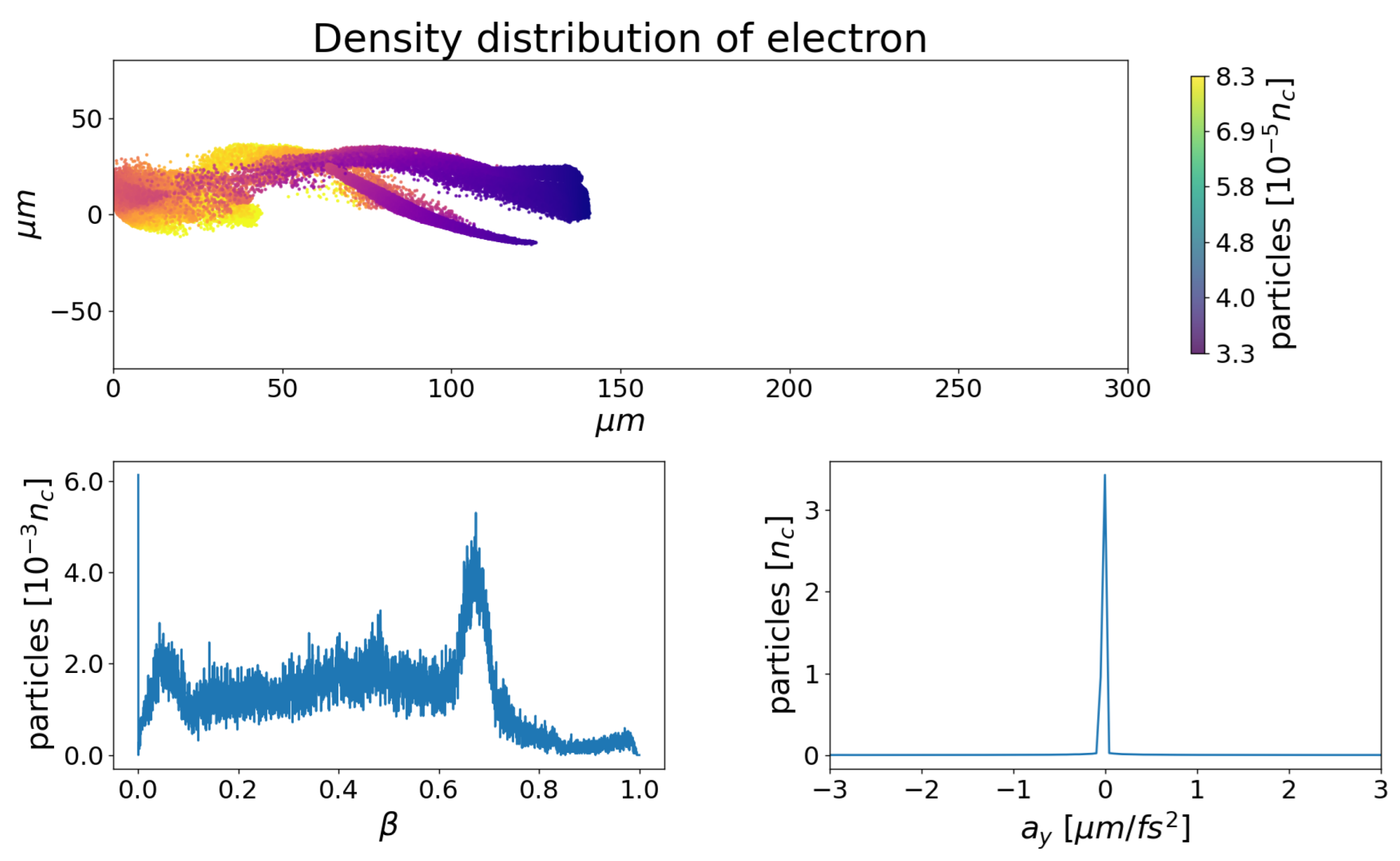
9.3.4. Slide-Away Electrons

There are certain fractions of plasma electrons that are pushed by the transverse plasma wakefields and propagate in the transverse direction. In practice, they would not affect the experiment since they are not moving toward the sensor, however, one would have to consider their hitting and reflection from the gas nozzle, which would induce background photon events.
Figure 26 is a snapshot of slide-away electrons. As pointed out previously, slide-away electrons slide toward the positive y direction, and are classified into a different category through the process.

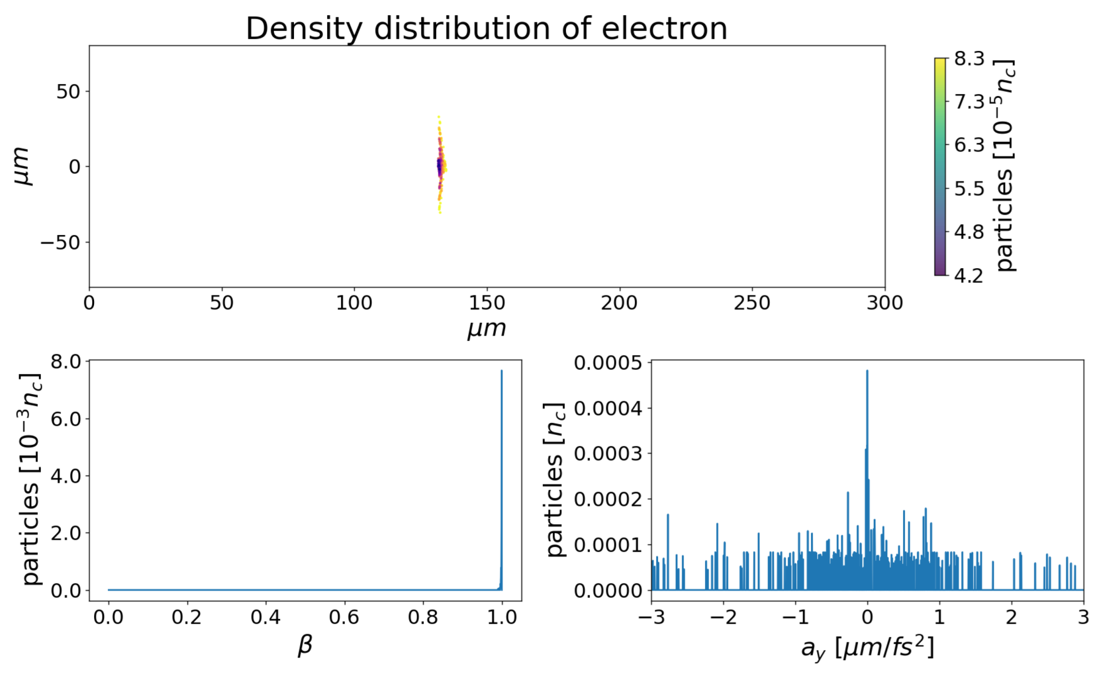
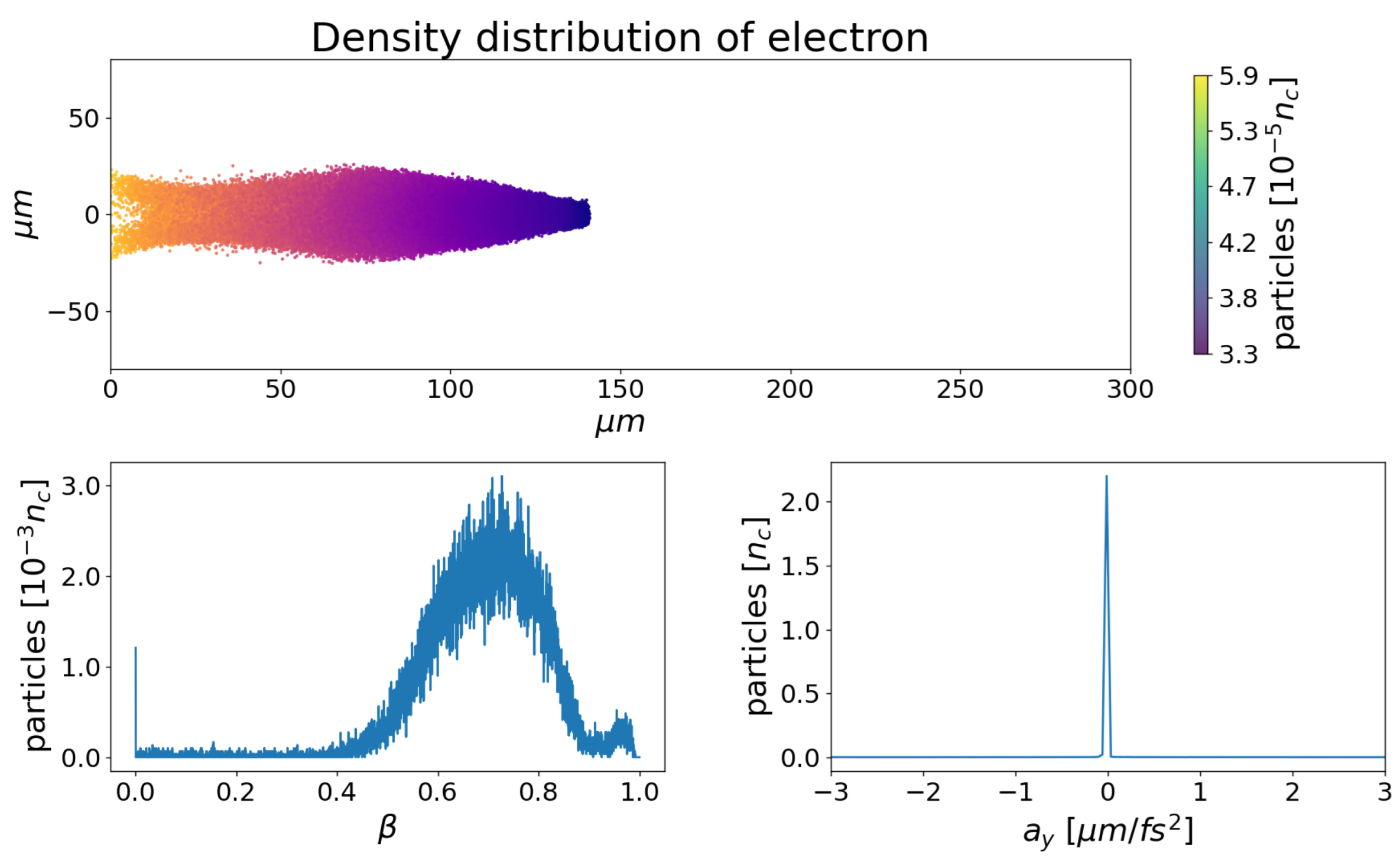
9.3.5. Transverse Oscillating Electrons

The last ones are the oscillating electrons. These are the electrons that are attracted by the Coulomb force of the plasma ion bubble and they oscillate around the laser trajectory in the traverse direction. Figure 27 shows the density distribution, velocity, and acceleration in the y-direction of these electrons.
This distribution has a tail that extends into the non-relativistic region. We expect that they would emit photons through synchrotron radiation, which can affect the identification of the Hawking photon signals.

9.3.6. Low-Frequency Soliton Radiations

We note that laser–plasma interaction also induces additional low-frequency background photons emitted by collective effects such as solitons, which are not included in the above discussion. Such near-plasma-frequency radiation was first pointed out by Bulanov [83] and has been recorded experimentally [35]. The radiation released by the solitons propagates essentially in the forward direction, where the seek-after partner photon signals are expected to be in the EUV range. Thus such soliton-induced radiation signals may not render competing backgrounds to our experiment. Nevertheless, we will further investigate this collective soliton effect to determine whether some of such radiation might be reflected backward so as to confuse the Hawking photons, whose wavelengths are indeed close.
Our next step is to estimate the radiation with the corresponding process according to these categories, and compare the result with the radiation spectrum generated by the PIC simulation code and assess their impacts on the AnaBHEL experiment.

10. Strategy of AnaBHEL

We execute the AnaBHEL project based on the following strategy.
Stage-1
R&D of the key components, namely the superconducting nanowire single-photon Hawking detector and the supersonic gas jet with the designed density profile, are mainly carried out at the Leung Center for Cosmology and Particle Astrophysics (LeCosPA), National Taiwan University. These are going well, as reported in the previous sections.
Stage-2
Dynamics of the laser-induced plasma mirror trajectory and its correspondence with the plasma density profile. The first attempt was scheduled at Kansai Photon Science Institute (KPSI) in Kyoto, Japan, using its PW laser facility, in the summer of 2022. We expect that the iterative interplay between the gas jet design and the laser–plasma interaction data acquisition is indispensable.
Stage-3
The full-scale analog black hole experiment used to detect Hawking and partner photons will be pursued when the Hawking detector is fully developed and the plasma mirror trajectory is characterized. It is our desire that the Stage-3 experiment be carried out at the Apollon Laser Facility in Saclay, France.

11. Conclusions

The information loss paradox associated with the black hole Hawking evaporation is arguably one of the most challenging issues in fundamental physics because it touches on a potential conflict between the two pillars of modern physics, i.e., general relativity and quantum field theory. Unfortunately, typical astrophysical stellar-size black holes are too cold and too young to be able to shed light on this paradox. Laboratory investigation of analog black holes may help to shed some light on this critical issue.
There have been various proposals for analog black holes. Different from the approach of invoking fluids (ordinary and superfluid via the Bose–Einstein condensate) that tries to mimic the curved spacetime related to the black hole environment, our approach attempts to create an accelerating boundary condition to a flat spacetime while relying on its nontrivial interplay with the quantum vacuum fluctuations. We believe that these different approaches have their respective pros and cons, and are complementary to each other. Together, a more complete picture of black hole evaporation would hopefully emerge.
Since its launch in 2018, the AnaBHEL collaboration has shown progress (although, there was the COVID-19 pandemic). Although the R&D is not yet complete, we are confident that the end is in sight.

Author Contributions

Conceptualization, P.C. and G.M.; methodology, P.C.; theory, K.-N.L., P.C., hardware, J.N., Y.-K.L., C.-E.L., S.-X.L., S.P., H.-Y.W., W.-P.W., M.B., J.-F.G., B.T. software, Y.-K.L., N.W.; validation, H.T.; investigation, A.P., M.K., Y.F., K.K., Y.-K.L., P.C., J.W.; writing—original draft preparation, P.C.; writing—review and editing, all authors; visualization, Y.-K.L., H.-Y.W., N.W.; project administration, P.C., S.P., B.T.; funding acquisition, P.C., S.P. All authors have read and agreed to the published version of the manuscript.

Funding

The Taiwan team and P.C. are supported by Taiwan’s Ministry of Science and Technology (MOST) under project number 110-2112-M-002-031, and by the Leung Center for Cosmology and Particle Astrophysics (LeCosPA), National Taiwan University. S.P. is further supported by Taiwan’s Ministry of Education (grant MoE/NTU grant number: 111L104013). M.K. and A.P. are supported by JSPS Kakenhi JP19H00669 and JP19KK0355 and Strategic Grant by the QST President: IRI. K.K. is supported by JSPS Kakenhi (grant number JP21H01103).

Data Availability Statement

Not applicable.

Acknowledgments

The authors are grateful to the Computer and Information Networking Center, National Taiwan University, for the support of the high-performance computing facilities.

Conflicts of Interest

The funders had no role in the design of the study; in the collection, analyses, or interpretation of data; in the writing of the manuscript, or in the decision to publish the results.

References

  1. Hawking, S.W. Particle Creation by Black Holes. Commun. Math. Phys. 1975, 43, 199, Erratum in Commun. Math. Phys. 1976, 46, 206. [Google Scholar] [CrossRef]
  2. Hawking, S.W. Breakdown of predictability in gravitational collapse. Phys. Rev. D 1976, 14, 2460–2473. [Google Scholar] [CrossRef]
  3. Susskind, L.; Thorlacius, L.; Uglum, J. The stretched horizon and black hole complementarity. Phys. Rev. D 1993, 48, 3743–3761. [Google Scholar] [CrossRef] [PubMed] [Green Version]
  4. Almheiri, A.; Marolf, D.; Polchinski, J.; Sully, J. Black Holes: Complementarity or Firewalls? J. High Energy Phys. 2013, 2, 62. [Google Scholar] [CrossRef] [Green Version]
  5. Almheiri, A.; Marolf, D.; Polchinski, J.; Stanford, D.; Sully, J. An apologia for firewalls. J. High Energy Phys. 2013, 9, 18. [Google Scholar] [CrossRef] [Green Version]
  6. Mathur, S.D. The information paradox: A pedagogical introduction. Class. Quant. Grav. 2009, 26, 224001. [Google Scholar] [CrossRef] [Green Version]
  7. Chen, P.; Ong, Y.C.; Page, D.N.; Sasaki, M.; Yeom, D. Naked Black Hole Firewalls. Phys. Rev. Lett. 2016, 116, 161304. [Google Scholar] [CrossRef] [Green Version]
  8. Bousso, R.; Porrati, M. Soft hair as a soft wig. Class. Quant. Grav. 2017, 34, 204001. [Google Scholar] [CrossRef] [Green Version]
  9. Giddings, S.B. Gravitational dressing, soft charges, and perturbative gravitational splitting. Phys. Rev. D 2019, 100, 126001. [Google Scholar] [CrossRef] [Green Version]
  10. Hawking, S.; Perry, M.; Strominger, A. Soft Hair on Black Holes. Phys. Rev. Lett. 2016, 116, 231301. [Google Scholar] [CrossRef]
  11. Chen, P.; Ong, Y.C.; Yeom, D. Black Hole Remnants and the Information Loss Paradox. Phys. Rep. 2015, 603, 1–45. [Google Scholar] [CrossRef] [Green Version]
  12. Almheiri, A.; Engelhardt, N.; Marolf, D.; Maxfield, H. The entropy of bulk quantum fields and the entanglement wedge of an evaporating black hole. J. High Energy Phys. 2019, 12, 063. [Google Scholar] [CrossRef] [Green Version]
  13. Almheiri, A.; Mahajan, R.; Maldacena, J.; Zhao, Y. The Page curve of the Hawking radiation from semiclassical geometry. J. High Energy Phys. 2020, 3, 149. [Google Scholar] [CrossRef] [Green Version]
  14. Penington, G.; Shenker, S.H.; Stanford, D.; Yang, Z. Replica wormholes and the black hole interior. J. High Energy Phys. 2022, 3, 205. [Google Scholar] [CrossRef]
  15. Almheiri, A.; Hartman, T.; Maldacena, J.; Shaghoulian, E.; Tajdini, A. Replica Wormholes and the Entropy of the Hawking Radiation. J. High Energy Phys. 2020, 5, 13. [Google Scholar] [CrossRef]
  16. Chen, P.; Sasaki, M.; Yeom, D.; Yoon, J. Solving information loss paradox via Euclidean path integral. Int. J. Mod. Phys. D 2022, 8, 14. [Google Scholar]
  17. Unruh, W.G. Experimental Black-Hole Evaporation? Phys. Rev. Lett. 1981, 46, 1351. [Google Scholar] [CrossRef]
  18. Unruh, W.G. Sonic analogue of black holes and the effects of high frequencies on black hole evaporation. Phys. Rev. D 1995, 51, 2827. [Google Scholar] [CrossRef] [Green Version]
  19. Schützhold, R.; Unruh, W.G. Hawking Radiation in an Electromagnetic Waveguide? Phys. Rev. Lett. 2005, 95, 031301. [Google Scholar] [CrossRef] [Green Version]
  20. Yablonovitch, E. Accelerating reference frame for electromagnetic waves in a rapidly growing plasma: Unruh-Davies-Fulling-DeWitt radiation and the nonadiabatic Casimir effect. Phys. Rev. Lett. 1989, 62, 1742. [Google Scholar] [CrossRef]
  21. Belgiorno, F.; Cacciatori, S.L.; Clerici, M.; Gorini, V.; Ortenzi, G.; Rizzi, L.; Rubino, E.; Sala, V.G.; Faccio, D. Hawking Radiation from Ultrashort Laser Pulse Filaments. Phys. Rev. Lett. 2010, 105, 203901. [Google Scholar] [CrossRef] [PubMed]
  22. De Nova, M.; Golubkov, J.R.; Kolobov, K.; Steinhauer, J. Observation of thermal Hawking radiation and its temperature in an analogue black hole. Nature 2019, 569, 688. [Google Scholar] [CrossRef] [PubMed] [Green Version]
  23. Chen, P.; Tajima, T. Testing Unruh Radiation with Ultraintense Lasers. Phys. Rev. Lett. 1999, 83, 256. [Google Scholar] [CrossRef] [Green Version]
  24. Fulling, S.A.; Davies, P. Radiation from a moving mirror in two dimensional space-time: Conformal anomaly. Proc. R. Soc. Lond. 1976, A348, 393. [Google Scholar]
  25. Chen, P.; Mourou, G. Accelerating Plasma Mirrors to Investigate the Black Hole Information Loss Paradox. Phy. Rev. Lett. 2017, 118, 045001. [Google Scholar] [CrossRef] [PubMed] [Green Version]
  26. Chen, P.; Mourou, G. Trajectory of a flying plasma mirror traversing a target with density gradient. Phys. Plasmas 2020, 27, 123106. [Google Scholar] [CrossRef]
  27. Aspect, A.; Grangier, P.; Roger, G. Experimental Realization of Einstein-Podolsky-Rosen-Bohm Gedankenexperiment: A New Violation of Bell’s Inequalities. Phys. Rev. Lett. 1982, 49, 91. [Google Scholar] [CrossRef] [Green Version]
  28. Bulanov, S.V.; Esirkepov, T.Z.; Tajima, T. Light Intensification towards the Schwinger Limit. Phys. Rev. Lett. 2003, 91, 085001. [Google Scholar] [CrossRef]
  29. Naumova, N.M.; Nees, J.A.; Sokolov, I.V.; Hou, B.; Mourou, G.A. Relativistic Generation of Isolated Attosecond Pulses in a λ3 Focal Volume. Phys. Rev. Lett. 2004, 92, 063902-1. [Google Scholar] [CrossRef]
  30. Esirkepov, T.Z.; Bulanov, S.V.; Tajima, T. Flying Mirrors: Relativistic Plasma Wake Caustic Light Intensification. In Quantum Aspects of Beam Physics; Chen, P., Reil, K., Eds.; World Scientific: Singapore, 2004; p. 186. [Google Scholar]
  31. Bulanov, S.V.; Esirkepov, T.Z.; Kando, M.; Pirozhkov, A.S.; Rosanov, N.N. Relativistic mirrors in plasmas. Novel results and perspectives. Physics-Uspekhi 2013, 56, 429. [Google Scholar] [CrossRef]
  32. Pirozhkov, A.; Ma, J.; Kando, M.; Esirkepov, T.Z.; Fukuda, Y.; Chen, L.-M.; Daito, I.; Ogura, K.; Homma, T.; Hayashi, Y.; et al. Frequency multiplication of light back-reflected from a relativistic wake wave. Phys. Plasmas 2007, 14, 123106. [Google Scholar] [CrossRef]
  33. Kando, M.; Fukuda, Y.; Pirozhkov, A.S.; Ma, J.; Daito, I.; Chen, L.-M.; Esirkepov, T.Z.; Ogura, K.; Homma, T.; Hayashi, Y.; et al. Demonstration of Laser-Frequency Upshift by Electron-Density Modulations in a Plasma Wakefield. Phys. Rev. Lett. 2007, 99, 135001. [Google Scholar] [CrossRef] [PubMed]
  34. Pirozhkov, A.S.; Esirkepov, T.Z.; Kando, M.; Fukuda, Y.; Ma, J.; Chen, L.-M.; Daito, I.; Ogura, K.; Homma, T.; Hayashi, Y.; et al. Demonstration of light reflection from the relativistic mirror. J. Phys. Conf. Ser. 2008, 112, 042050. [Google Scholar] [CrossRef]
  35. Kando, M.; Pirozhkov, A.S.; Kawase, K.; Esirkepov, T.Z.; Fukuda, Y.; Kiriyama, H.; Okada, H.; Daito, I.; Kameshima, T.; Hayashi, Y.; et al. Enhancement of Photon Number Reflected by the Relativistic Flying Mirror. Phys. Rev. Lett. 2009, 103, 235003. [Google Scholar] [CrossRef] [PubMed]
  36. Wilczek, F. Quantum Purity at a Small Price: Easing a Black Hole Paradox. In Proceedings of the Houston Conference Black Holes, Houston, TX, USA, 16–18 January 1992. [Google Scholar]
  37. Hotta, M.; Schutzhold, R.; Unruh, W.G. Partner particles for moving mirror radiation and black hole evaporation. Phys. Rev. D 2015, 91, 124060. [Google Scholar] [CrossRef] [Green Version]
  38. Bardeen, J. Black hole evaporation without an event horizon. arXiv 2014, arXiv:1406.4098. [Google Scholar] [CrossRef]
  39. Page, D.N. Information in black hole radiation. Phys. Rev. Lett. 1993, 71, 3743. [Google Scholar] [CrossRef] [Green Version]
  40. Hotta, M.; Sugita, A. The Fall of Black Hole Firewall: Natural Nonmaximal Entanglement for Page Curve. Prog. Theor. Exp. Phys. 2015, 2015, 123B04. [Google Scholar] [CrossRef] [Green Version]
  41. Chen, P.; Yeom, D.-H. Entropy evolution of moving mirrors and the information loss problem. Phys. Rev. D 2017, 96, 025016. [Google Scholar] [CrossRef] [Green Version]
  42. Good, M.R.R.; Linder, E.V.; Wilczek, F. Moving mirror model for quasithermal radiation fields. Phys. Rev. D 2020, 101, 025012. [Google Scholar] [CrossRef] [Green Version]
  43. Good, M.R.R.; Linder, E.V. Eternal and evanescent black holes and accelerating mirror analogs. Phys. Rev. D 2018, 97, 065006. [Google Scholar] [CrossRef] [Green Version]
  44. Tajima, T.; Dawson, J.M. Laser Electron Accelerator. Phys. Rev. Lett. 1979, 43, 267. [Google Scholar] [CrossRef]
  45. Chen, P.; Dawson, J.M.; Huff, R.; Katsouleas, T. Acceleration of Electrons by the Interaction of a Bunched Electron Beam with a Plasma. Phys. Rev. Lett. 1985, 54, 693. [Google Scholar] [CrossRef] [Green Version]
  46. Chen, P.; Reil, K. (Eds.) Quantum, Aspects of Beam Physics; World Scientific: Singapore, 2004. [Google Scholar]
  47. Mourou, G.; Tajima, T. Zetta-Exawatt Science and Technology. Eur. Phys. J. Spec. Top. 2014, 223. Available online: https://portail.polytechnique.edu/izest/en/en/science-techn/science (accessed on 7 December 2022).
  48. Davies, P.C.W.; Fulling, S.A. Radiation from moving mirrors and from black holes. Proc. R. Soc. A 1977, 356, 237. [Google Scholar]
  49. Birrell, N.D.; Davies, P.C.W. Quantum Fields in Curved Space. In Cambridge Monographs on Mathematical Physics; Cambridge University Press: Cambridge, UK, 1984. [Google Scholar]
  50. Liu, Y.K.; Chen, P.; Fang, Y. Reflectivity and Spectrum of Relativistic Flying Plasma Mirrors. Phys. Plasmas 2021, 10, 103301. [Google Scholar] [CrossRef]
  51. DeWitt, S. Quantum field theory in curved spacetime. Phys. Rep. 1975, 19, 295. [Google Scholar] [CrossRef]
  52. Barton, G.; Calogeracos, A. On the quantum electrodynamics of a dispersive mirror.: I. mass shifts, radiation, and radiative reaction. Ann. Phys. N. Y. 1995, 238, 227. [Google Scholar] [CrossRef]
  53. Nicolaevici, N. Quantum radiation from a partially reflecting moving mirror. Class. Quant. Grav. 2001, 18, 619. [Google Scholar] [CrossRef]
  54. Nicolaevici, N. Semitransparency effects in the moving mirror model for Hawking radiation. Phys. Rev. D 2009, 80, 125003. [Google Scholar] [CrossRef]
  55. Lin, K.-N.; Chou, C.-E.; Chen, P. Particle production by a relativistic semitransparent mirror in (1+3)D Minkowski spacetime. Phys. Rev. D 2021, 103, 025014. [Google Scholar] [CrossRef]
  56. Lin, K.-N.; Chen, P. Particle production by a relativistic semitransparent mirror of finite transverse size. arXiv 2021, arXiv:2107.09033. [Google Scholar]
  57. Kaganovich, D.; Gordon, D.F.; Helle, H.; Ting, A. Shaping gas jet plasma density profile by laser generated shock waves. J. Appl. Phys. 2014, 116, 013304. [Google Scholar] [CrossRef]
  58. Helle, M.H.; Gordon, D.F.; Kaganovich, D.; Chen, Y.; Palastro, J.P.; Ting, A. Laser-Accelerated Ions from a Shock-Compressed Gas Foil. Phys. Rev. Lett. 2016, 117, 165001. [Google Scholar] [CrossRef] [PubMed] [Green Version]
  59. Schmid, K.; Buck, A.; Sears, C.M.S.; Mikhailova, J.M.; Tautz, R.; Herrmann, D.; Geissler, M.; Krausz, F.; Veisz, L. Density-transition based electron injector for laser driven wakefield accelerators. Phys. Rev. ST Accel. Beams 2010, 13, 091301. [Google Scholar] [CrossRef]
  60. Fang-Chiang, L.; Mao, H.-S.; Tsai, H.-E.; Ostermayr, T.; Swanson, K.K.; Barber, S.K.; Steinke, S.; van Tilborg, J.; Geddes, C.G.R.; Leemans, W.P. Gas density structure of supersonic flows impinged on by thin blades for laser–plasma accelerator targets. Phys. Fluids 2020, 32, 066108. [Google Scholar] [CrossRef]
  61. Hsu-hsin, C. Construction of a 10-TW Laser of High Coherence and Stability and Its Application in Laser-Cluster Interaction and X-ray Lasers. Ph.D. Thesis, National Taiwan University, Taipei, Taiwan, 2005. [Google Scholar]
  62. Golovin, G.; Banerjee, S.; Chen, S.; Powers, N.; Liu, C.; Yan, W.; Zhang, J.; Zhang, P.; Zhao, B.; Umstadter, D. Control and optimization of a staged laser-wakefield accelerator. Nucl. Instrum. Methods Phys. Res. Sect. A 2016, 830, 375. [Google Scholar] [CrossRef] [Green Version]
  63. Kim, K.N.; Hwangbo, Y.; Jeon, S.-G.; Kim, J. Characteristics of the Shock Structure for Transition Injection in Laser Wakefield Acceleration. J. Korean Phys. Soc. 2018, 73, 561. [Google Scholar] [CrossRef]
  64. Fang, M.; Zhang, Z.; Wang, W.; Liu, J.; Li, R. Sharp plasma pinnacle structure based on shockwave for an improved laser wakefield accelerator. Plasma Phys. Controlled Fusion 2018, 60, 075008. [Google Scholar] [CrossRef]
  65. Hansen, A.M.; Haberberger, D.; Katz, J.; Mastrosimone, D.; Follett, R.K.; Froula, D.H. Supersonic gas-jet characterization with interferometry and Thomson scattering on the OMEGA Laser System. Rev. Sci. Instrum. 2018, 89, 10C103. [Google Scholar] [CrossRef]
  66. Couperus, J.P.; Köhler, A.; Wolterink, T.A.W.; Jochmann, A.; Zarini, O.; Bastiaens, H.M.J.; Boller, K.J.; Irman, A.; Schramm, U. Tomographic characterisation of gas-jet targets for laser wakefield acceleration. Nucl. Instrum. Methods Phys. Res. Sect. A 2016, 830, 504. [Google Scholar] [CrossRef]
  67. Adelmann, A.; Hermann, B.; Ischebeck, R.; Kaluza, M.C.; Locans, U.; Sauerwein, N.; Tarkeshian, R. Real-Time Tomography of Gas-Jets with a Wollaston Interferometer. Appl. Sci. 2018, 8, 443. [Google Scholar] [CrossRef] [Green Version]
  68. Epstein, A.H. MIT Gas Turbine Lab Report. 1974, p. 117. Available online: https://www.gas-turbine-lab.mit.edu/gtl-reports (accessed on 7 December 2022).
  69. Hanson, R.K.; Seitzman, J.M. Handbook of Flow Visualization; Routledge: London, UK, 2018; pp. 225–237. [Google Scholar]
  70. Settles, G.S. Schlieren and Shadowgraph Techniques; Spinger: Berlin, Germany, 2001. [Google Scholar]
  71. Mariani, R.; Lim, H.D.; Zang, B.; Vevek, U.S.; New, T.H.; Cui, Y.D. On the application of non-standard rainbow schlieren technique upon supersonic jets. J. Vis. 2020, 23, 383–393. [Google Scholar] [CrossRef]
  72. Greenshields, C.J.; Wellerm, H.G.; Gasparini, L.; Reese, J.M. Implementation of semi-discrete, non-staggered central schemes in a colocated, polyhedral, finite volume framework, for high-speed viscous flows. Int. J. Number. Methods Fluids 2010, 63, 1. [Google Scholar] [CrossRef] [Green Version]
  73. Zadeh, I.E.; Chang, J.; Los, J.W.N.; Gyger, S.; Elshaari, A.W.; Steinhauer, S.; Dorenbos, S.N.; Zwiller, V. Superconducting nanowire single-photon detectors: A perspective on evolution, state-of-the-art, future developments, and applications. Appl. Phys. Lett. 2021, 118, 190502. [Google Scholar] [CrossRef]
  74. Korzh, B.; Zhao, Q.-Y.; Allmaras, J.P.; Frasca, S.; Autry, T.M.; Bersin, E.A.; Beyer, A.D.; Briggs, R.M.; Bumble, B.; Conlangelo, M.; et al. Demonstration of sub-3 ps temporal resolution with a superconducting nanowire single-photon detector. Nat. Photonics 2020, 14, 250–255. [Google Scholar] [CrossRef] [Green Version]
  75. Korzh, B.; Zhao, Q.-Y.; Frasca, S.; Zhu, D.; Ramirez, E.; Bersin, E.; Colangelo, M.; Dane, A.E.; Beyer, A.D.; Allmaras, J.; et al. Wsi superconducting nanowire single photon detector with a temporal resolution below 5 ps. In Proceedings of the Conference on Lasers and Electro-Optics, Hong Kong, China, 29 July–3 August 2018; p. FW3F.3. [Google Scholar]
  76. Verma, V.B.; Korzh, B.; Walter, A.B.; Lita, A.E.; Briggs, R.M.; Colangelo, M.; Zhai, Y.; Wollman, E.E.; Beyer, A.D.; Allmaras, J.P.; et al. Single-Photon detection in the mid-infrared up to 10 micron wavelength using tungsten silicide superconducting nanowire detectors. APL Photonics 2021, 6, 056101. [Google Scholar] [CrossRef]
  77. Wollman, E.; Verma, V.B.; Walter, A.B.; Chiles, J.; Korzh, B.; Allmaras, J.P.; Zhai, Y.; Lita, A.E.; McCaughan, A.N.; Schmidt, E.; et al. Recent advances in superconducting nanowire single-photon detector technology for exoplanet transit spectroscopy in the mid-infrared. J. Astron. Telesc. Instruments Syst. 2021, 7, 011004. [Google Scholar] [CrossRef]
  78. Wollman, E.; Verma, V.B.; Lita, A.E.; Farr, W.H.; Shaw, M.D.; Mirin, R.P.; Nam, S.W. Kilopixel array of superconducting nanowire single-photon detectors. Opt. Express 2019, 27, 35279–35289. [Google Scholar] [CrossRef] [Green Version]
  79. Stupakov, G. Short-range wakefields generated in the blowout regime of plasma-wakefield acceleration. Phys. Rev. Accel. Beams 2018, 21, 041301. [Google Scholar] [CrossRef] [Green Version]
  80. Derouillat, J.; Beck, A.; Perez, F.; Vinci, T.; Chiaramello, M.; Grassi, A.; Fle, M.; Bouchard, G.; Plotnikov, I.; Aunai, N.; et al. SMILEI: A collaborative, open-source, multi-purpose particle-in-cell code for plasma simulation. Comp. Phys. Comm. 2018, 222, 351–373. [Google Scholar] [CrossRef] [Green Version]
  81. Pedregosa, F.; Varoquaux, G.; Gramfort, A.; Michel, V.; Thirion, B.; Grisel, O.; Blondel, M.; Prettenhofer, P.; Weiss, R.; Dubourg, V.; et al. Scikit-learn: Machine Learning in Python. J. Mach. Learn. Res. 2011, 12, 2825. [Google Scholar]
  82. Markidis, S.; Peng, I.B.; Podobas, A.; Jongsuebchoke, I.; Bengtsson, G.; Herman, P.A. Automatic Particle Trajectory Classification in Plasma Simulations. In Proceedings of the 2020 IEEE/ACM Workshop on Machine Learning in High Performance Computing Environments (MLHPC) and Workshop on Artificial Intelligence and Machine Learning for Scientific Applications (AI4S), Atlanta, GA, USA, 12 November 2020; pp. 64–71. [Google Scholar]
  83. Bulanov, S.V.; Esirkepov, T.Z.; Naumova, N.M.; Pegoraro, F.; Vshivkov, V.A. Solitonlike Electromagnetic Waves behind a Superintense Laser Pulse in a Plasma. Phys. Rev. Lett. 1999, 82, 3440. [Google Scholar] [CrossRef]
Figure 1. The analogy between the Hawking radiation from a true BH (left) and that from an accelerating mirror (right). One may intuitively appreciate the analogy based on Einstein’s Equivalence Principle.
Photonics 09 01003 g001
Figure 2. (Reproduced from Reference [25].) The ’worldline’ of an accelerating relativistic plasma mirror and its relation with vacuum fluctuations around the horizon. In particular, the entanglements between the Hawking particles (blue) emitted at early times and their partner particles (red) collected at late times are illustrated. The green strip represents either a burst of energy or zero-point fluctuations emitted when the acceleration stops abruptly.
Photonics 09 01003 g002
Figure 3. Schematic drawing of the concept of accelerating plasma mirror driven by an intense laser that traverses a plasma with a decreasing density. Due to the variation of the laser intensity in the transverse dimension, which is typically in Gaussian distribution, the flying plasma mirror induced by the laser is concave in the forward direction.
Photonics 09 01003 g003
Figure 4. PIC simulation of plasma mirror acceleration [50]. (a) A plasma target with a constant-plus-exponential density gradient, n p ( x ) = n p 0 ( 1 + e x / D ) 2 , n p ( x = 0 ) = 1.0 × 10 17 cm 3 . (b) Comparison of the plasma mirror speed, β = x ˙ M / c , between the analytic formula (solid blue curve) and the PIC simulations (orange circles). The two agree extremely well. Note that the convention of the laser propagation direction in this PIC simulation is from left to right, which is opposite to that in the typical theoretical treatment of flying mirrors as analog black holes.
Photonics 09 01003 g004
Figure 5. A conceptual design of the7 AnaBHEL experiment. The enlarged figure is a gaseous plasma target with a decreasing density profile where the penetrating optical laser pulse (red) would induce an accelerating flying plasma mirror (blue). Hawking photons would be emitted to the backside of the mirror, and would suffer from the Doppler redshift and be in the infrared range. The partner photons, on the other hand, would penetrate the semi-transparent plasma mirror and propagate in the same direction as that of the laser, which does not suffer from the Doppler redshift and would be in the EUV range.
Photonics 09 01003 g005
Figure 6. Frequency spectrum of analog Hawking particles [56]. The area shaded in red gives a total number of 0.27 while that shaded in blue gives 0.02 .
Photonics 09 01003 g006
Figure 7. (left) Sketch of the nozzle used in our work. (right) The photo of our nozzle.
Photonics 09 01003 g007
Figure 8. Schematic diagram of our Schlieren optics.
Photonics 09 01003 g008
Figure 9. The obtained image with our Schlieren imaging system. Supersonic jet with shock diamonds are shown.
Photonics 09 01003 g009
Figure 10. Two-dimensional map of the gradient of the refractive index, n / y , based on the (a) simulated result and (b) reconstructed data. Here, y and z are the horizontal and vertical coordinates, respectively.
Photonics 09 01003 g010
Figure 11. The line profile of n / y as a function of the vertical position z. The data successfully captured the positions of the first few shock diamonds.
Photonics 09 01003 g011
Figure 12. Sputtering machine for film production (Kao Duen Technology, Model: KD-UHV, N-11L17).
Photonics 09 01003 g012
Figure 13. NbN films on a sample holder as they come out from the sputtering machine. The blue sample pieces are 10 nm-thick NbN on the DBR substrate. The gray sample piece shown in the middle is 10 nm-thick NbN grown on the MgO substrate. The difference in color is due to the fine NbN layer thickness.
Photonics 09 01003 g013
Figure 14. MPMS3 SQUID magnetometer.
Photonics 09 01003 g014
Figure 15. Triton 500 Cryogenics setup by the NTU-CCMS group (left). Resistance versus temperature measurement of a NbN film sample grown on MgO substrate (right).
Photonics 09 01003 g015
Figure 16. Baseline SNSPD sensor prototype autoCAD drawing.
Photonics 09 01003 g016
Figure 17. Nanowire prototype fabricated by the AnaBHEL Collaboration, shown here through the autoCAD zoom-in.
Photonics 09 01003 g017
Figure 18. Electron beam lithography machine located in (Left) Academic Sinica laboratories (EBL, ELS-7000 ELIONIX); and (Right) Junsun Tech MGS-500 sputtering machine installed at the NEMS center of NTU.
Photonics 09 01003 g018
Figure 19. Reflectivity of a distributed Bragg reflector structure used to enhance the efficiency of sensors sensitive at 1550 nm. Data are shown in black and the FDTD simulation is in red.
Photonics 09 01003 g019
Figure 20. Single-photon calibration setup using SPAD.
Photonics 09 01003 g020
Figure 21. Test-bench setup for testing sensors at 1550 nm using fibers connected to sensors.
Photonics 09 01003 g021
Figure 22. Test-bench setup for testing sensors in open-air transmission by bringing the lasers in the cryostat. In the actual AnaBHEL experiment, the entire experimental chamber would be embedded in a cryogenic system with a high vacuum.
Photonics 09 01003 g022
Figure 23. Electrons accelerated by the laser wakefield acceleration (LWFA) mechanism. The top figure is the electron density distribution shown by different colors The bottom left figure is the velocity distribution in β = v / c , where v is the velocity of the electron and c is the speed of light. bottom right of the figure shows the acceleration of the electron on the y-axis.
Photonics 09 01003 g023
Figure 24. Snowplowed electrons. The top figure is the electron density distribution shown by color. The bottom left figure is the velocity distribution in β = v / c , where v is the velocity of the electron and c is the speed of light. The bottom right of the figure shows the acceleration of the electron on the y-axis.
Photonics 09 01003 g024
Figure 25. Backward accelerated electrons. The top figure is the electron density distribution shown by color. The bottom left figure is the velocity distribution in β = v / c , where v is the velocity of the electron and c is the speed of light. bottom right of the figure shows the acceleration of the electron on the y-axis.
Photonics 09 01003 g025
Figure 26. Slide-away electrons. The top figure is the electron density distribution shown by color. The bottom left figure is the velocity distribution in β = v / c , where v is the velocity of the electron and c is the speed of light. bottom right of the figure shows the acceleration of the electron on the y-axis.
Photonics 09 01003 g026
Figure 27. Oscillating electrons. The top figure is the electron density distribution shown by color. The bottom left figure is the velocity distribution in β = v / c , where v is the velocity of the electron and c is the speed of light. bottom right of the figure shows the acceleration of the electrons in the y-axis.
Photonics 09 01003 g027
Table 1. The maximum gradients of the electron number densities obtained from different groups. Our target value is also shown.
MethodLaser-Induced Shock WaveBlade-Induced Shock WaveOur Target Value
GroupsKagonovich et al. (2014) [57]Schmid et al. (2010) [59]Fang-Chiang et al. (2020) [60]
( n e x ) m a x [ cm 4 ] 10 22 4 × 10 22 10 20 2 × 10 20
Table 2. SNSPD superconducting material properties and performance for specific designs summarized in [73]. Operating prototype WSi sensors for wavelengths close to 10 μ m have been reported in [76].
MaterialCurie T (K)Operating T (K)Wavelength ( μ m)Efficiency [%]t-Jitter (ps)
Requirements<101–4>10 (for UV: 1–100 ns)>95<10
NbN100.8–2.11.5592–98.240–106
NbTiN142.5–2.81.5592–99.514.8–34
WSi30.12–21.5593–98150
MoSi<30.8–1.21.5580–8726–76
MoSi (UV)5<40.2508560
Publisher’s Note: MDPI stays neutral with regard to jurisdictional claims in published maps and institutional affiliations.

