Joule-Level Twelve-Pass LD End-Pumped Bonded Neodymium Glass Laser Amplifier

 , ,
, ,
Abstract
:
1. Introduction
2. Experimental Setup
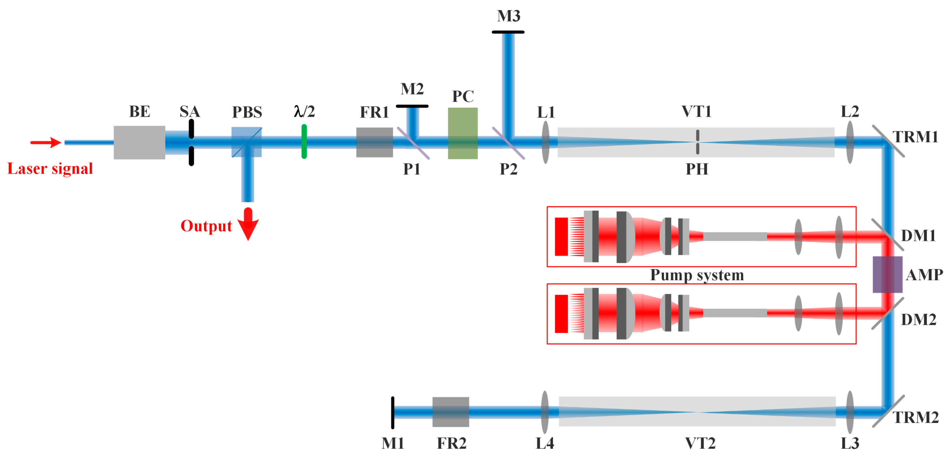
2.1. Amplification System Setup
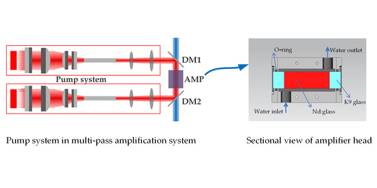
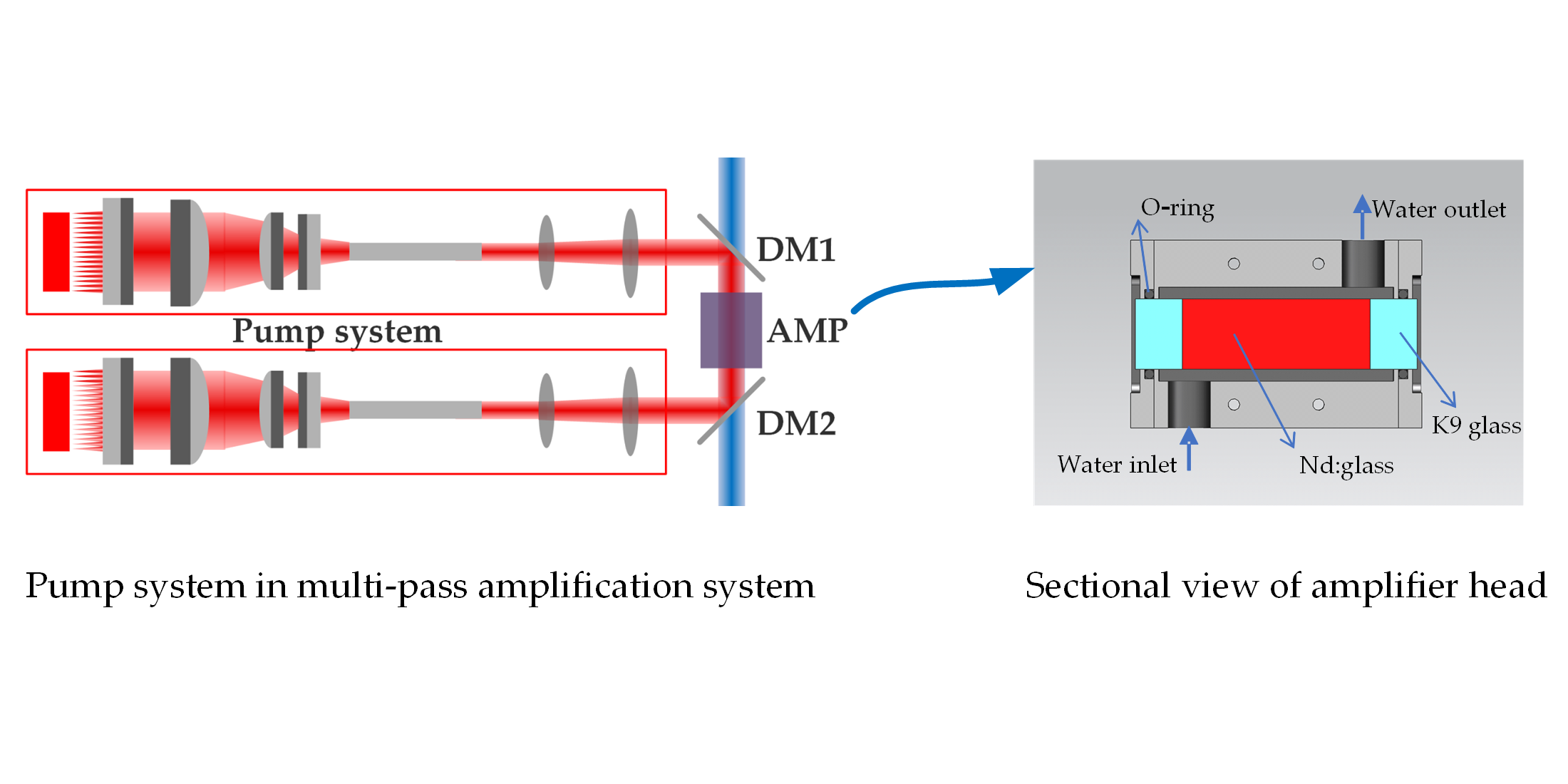
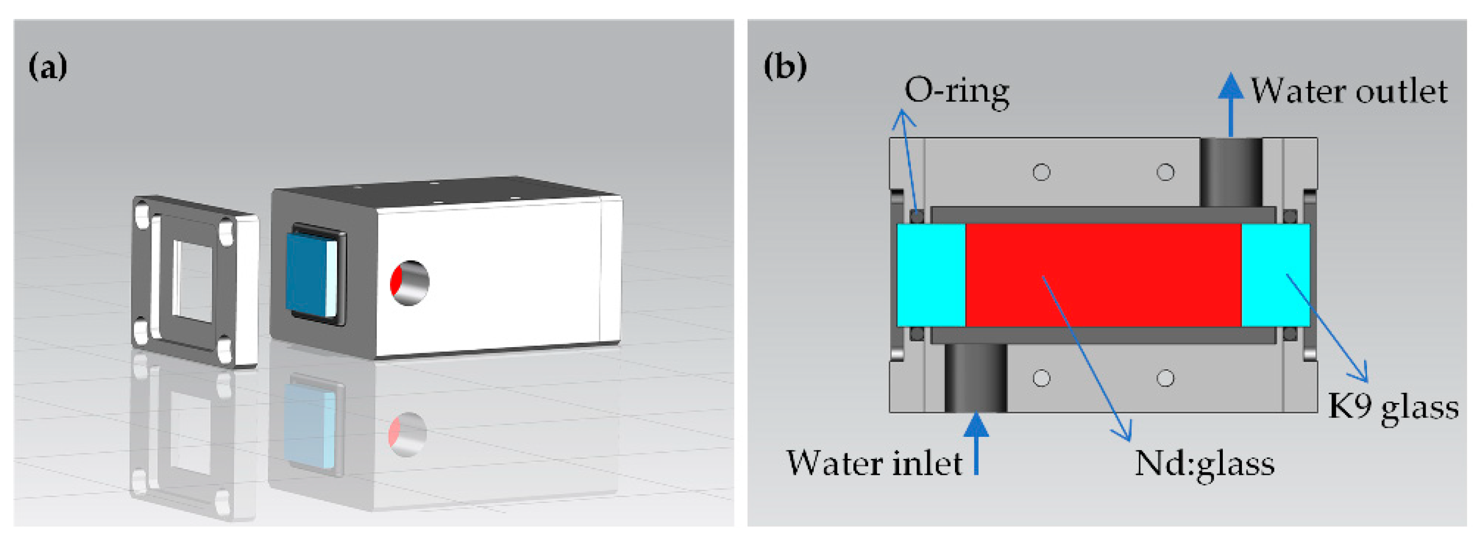
2.2. Amplifier Head
3. Experimental Results and Discussion
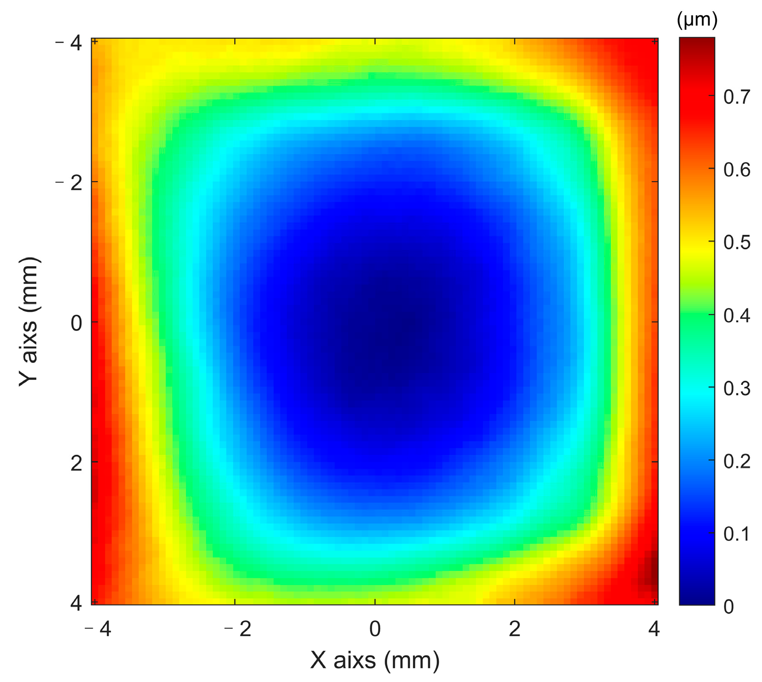
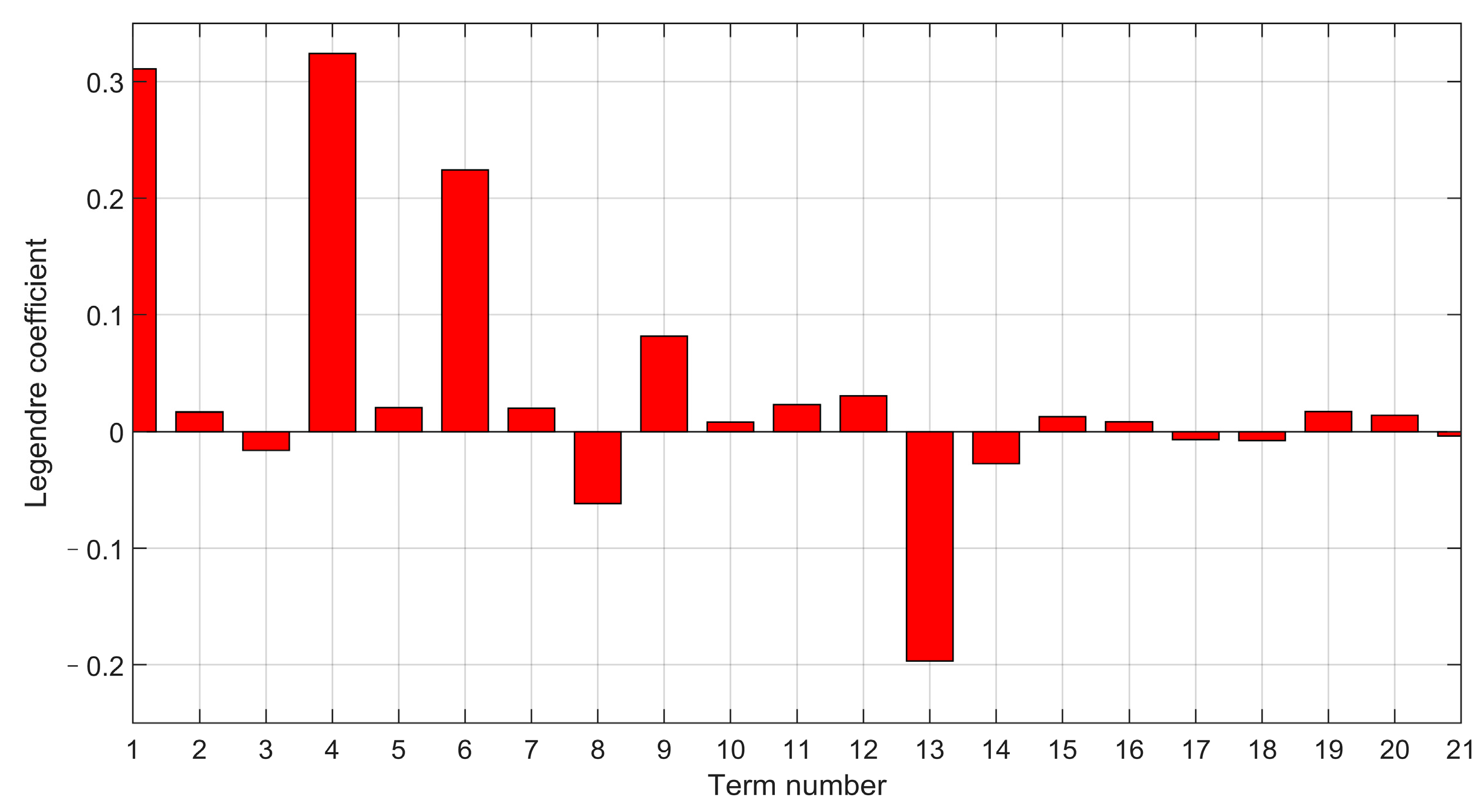
3.1. Thermal Effects
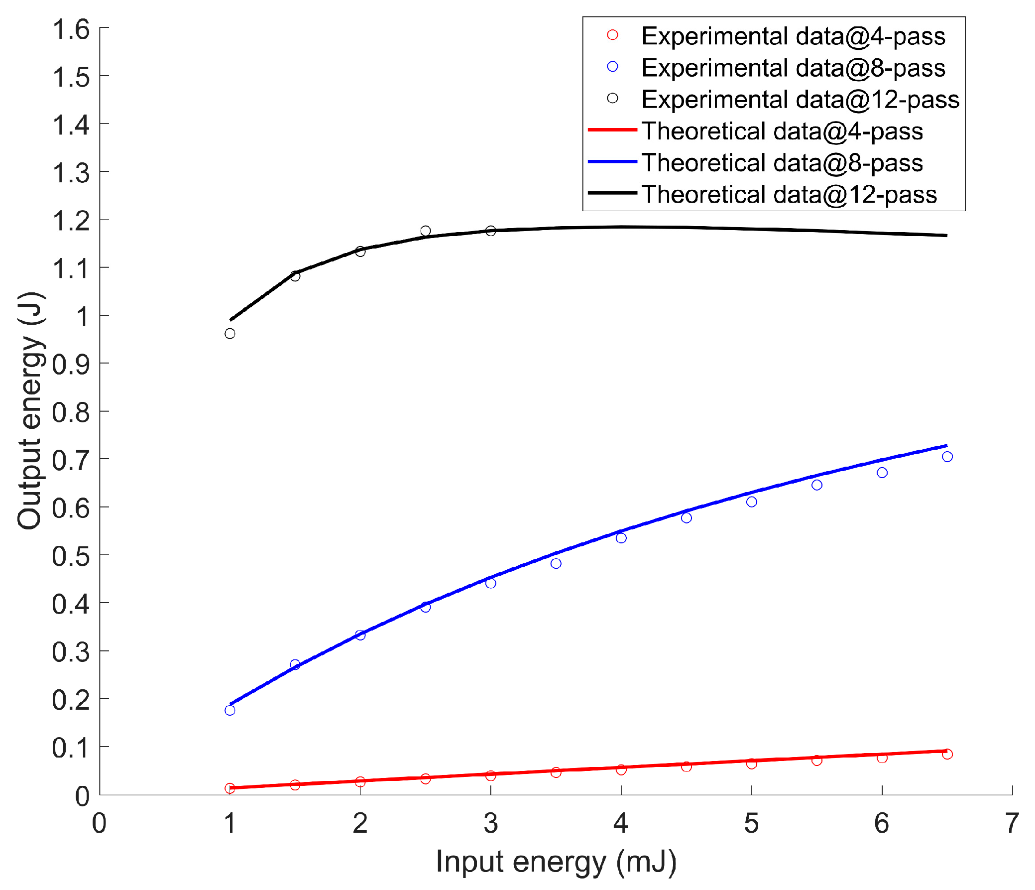
3.2. Output Energy
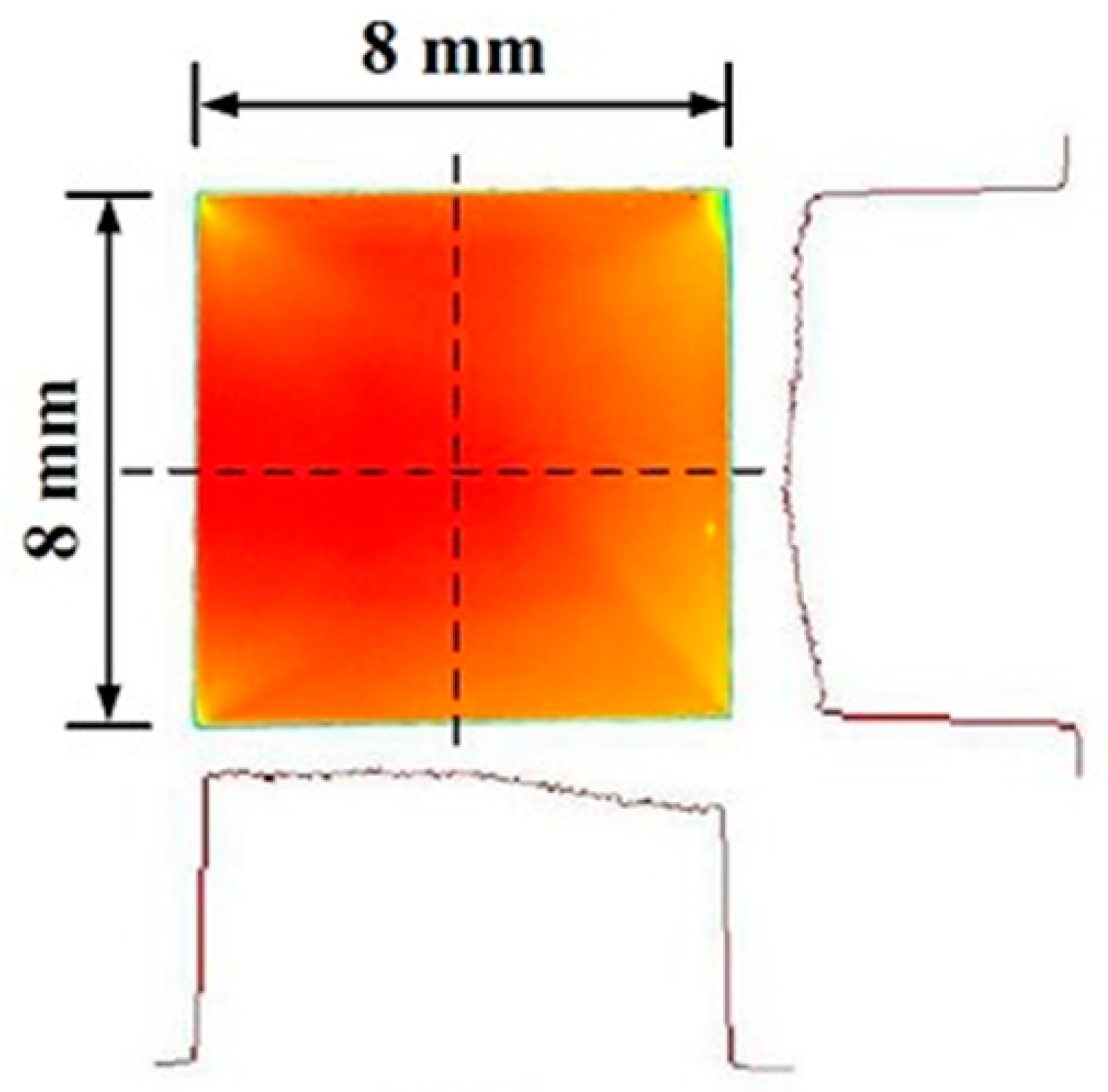
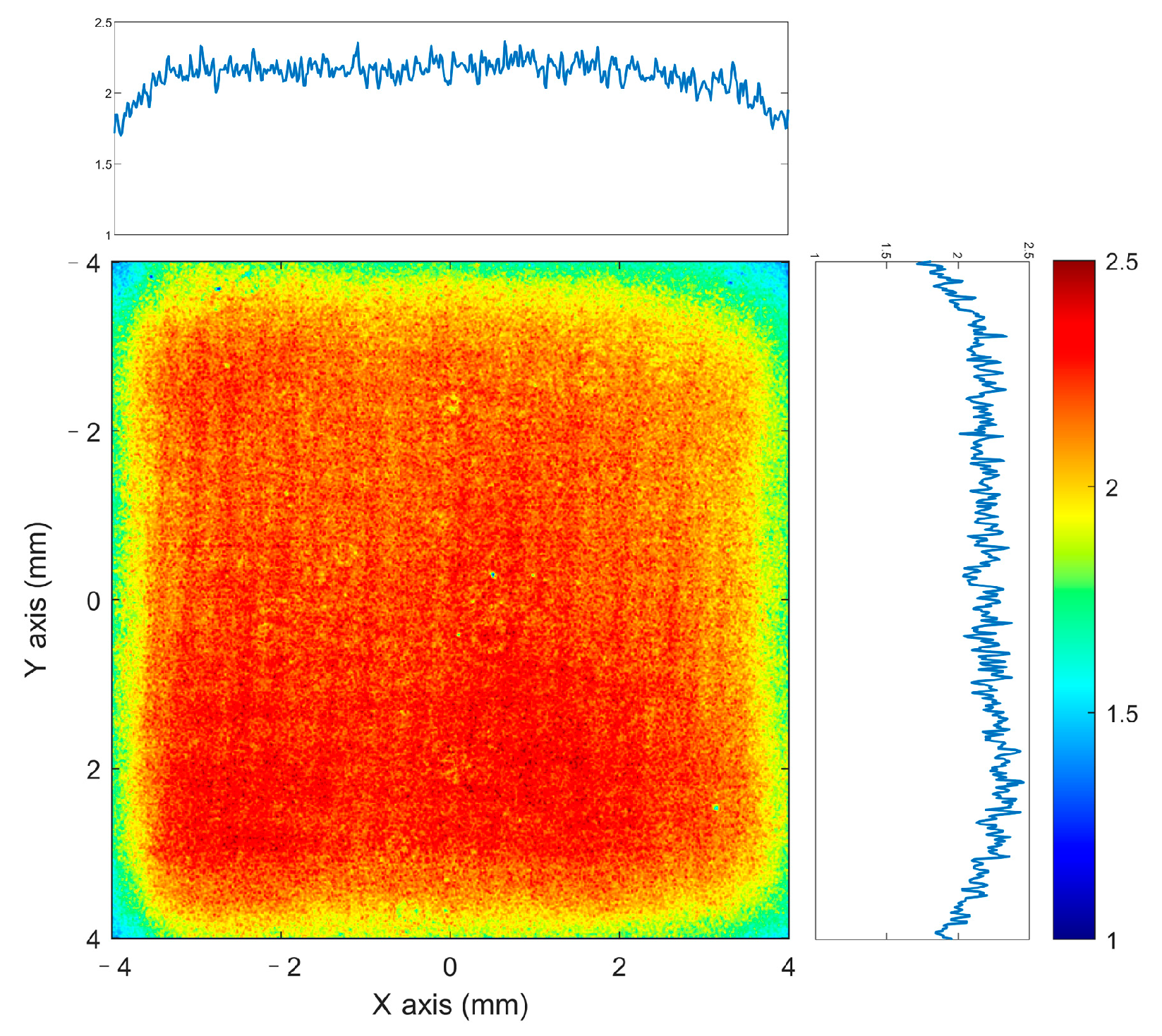
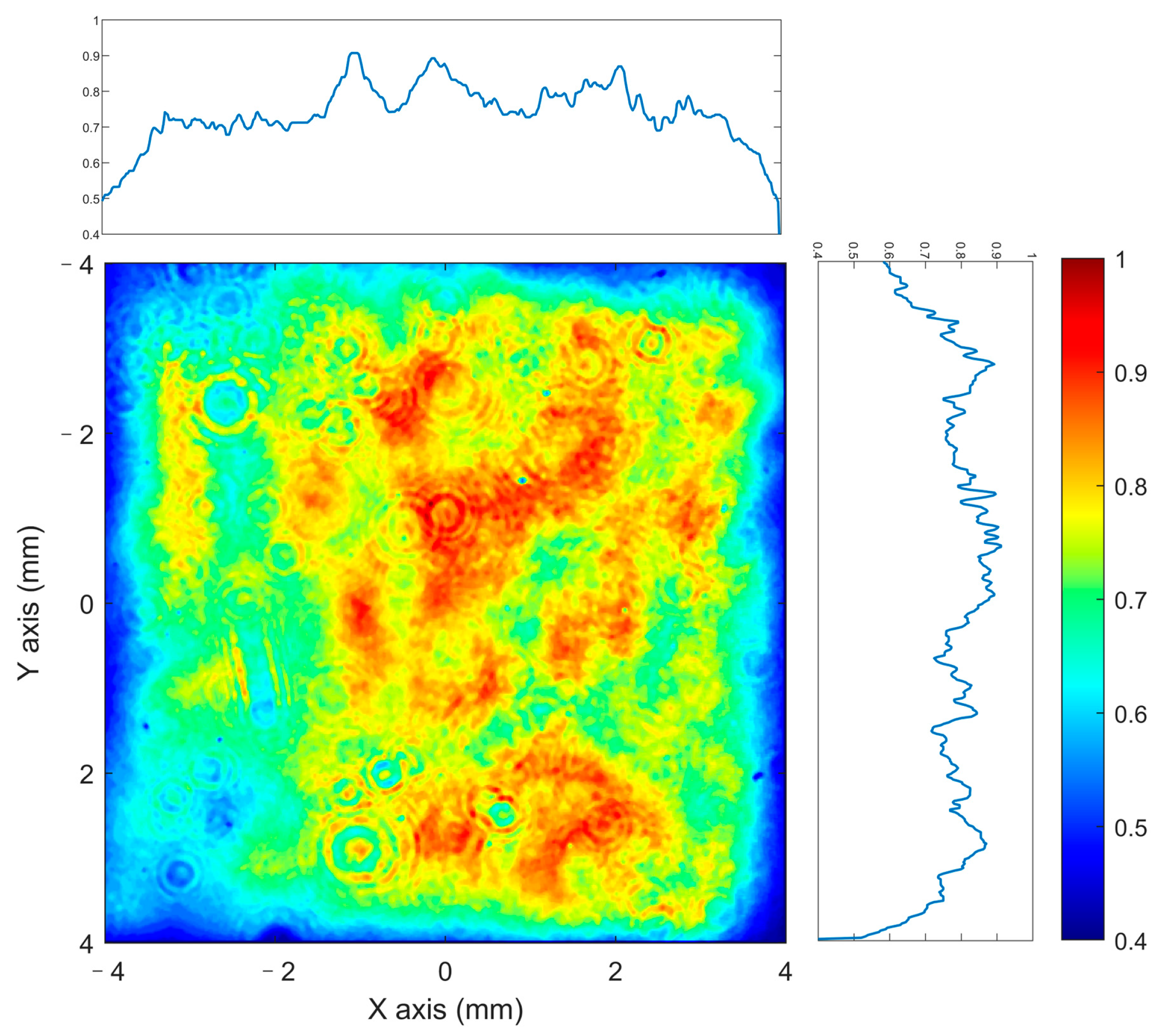
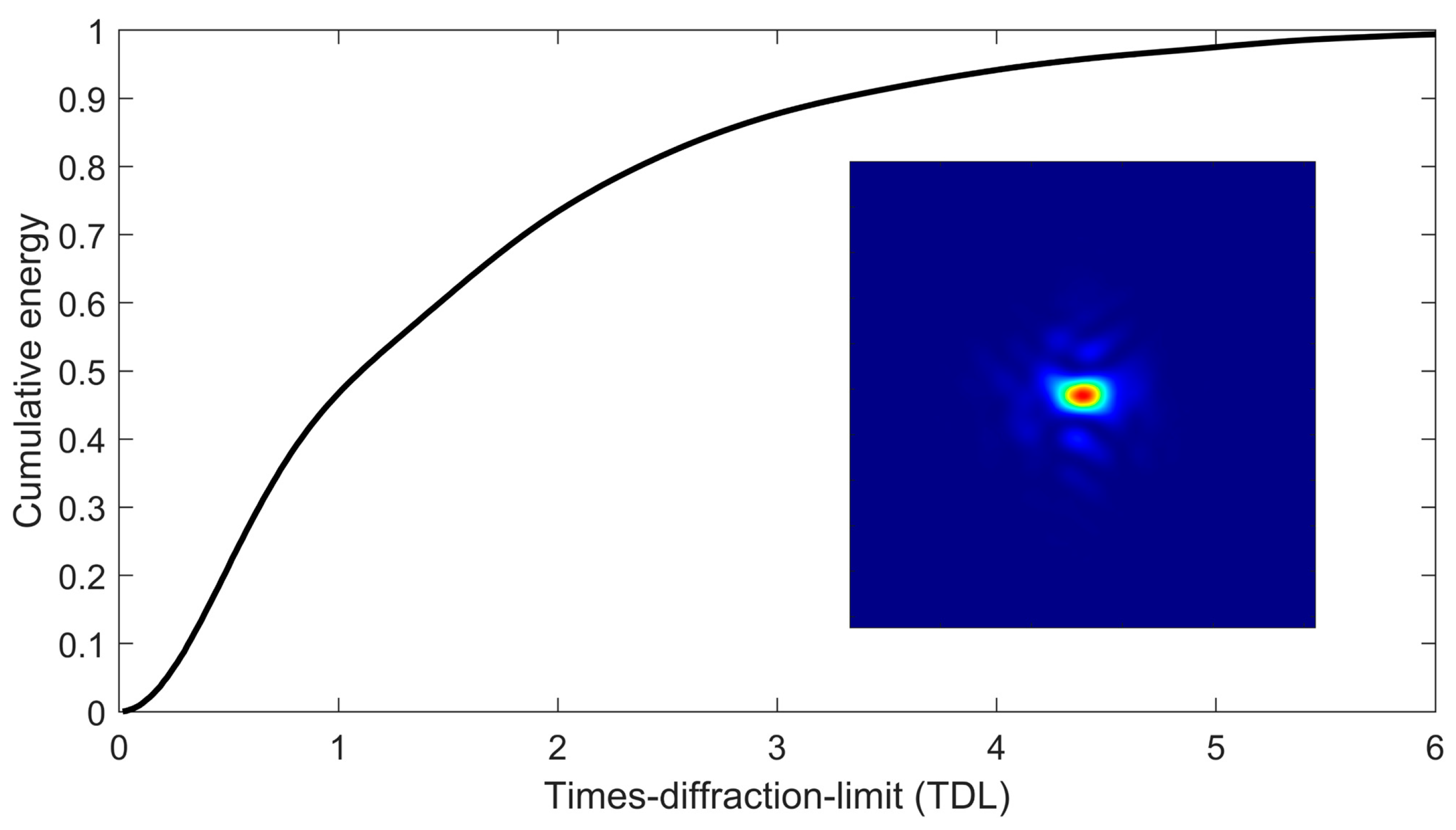
3.3. Beam Quality
4. Conclusions
Author Contributions
Funding
Institutional Review Board Statement
Informed Consent Statement
Conflicts of Interest
References
- Zhu, J.; Zhu, J.; Li, X.; Zhu, B.; Ma, W.; Lu, X.; Fan, W.; Liu, Z.; Zhou, S.; Xu, G.; et al. Status and development of high-power laser facilities at the NLHPLP. High Power Laser Sci. Eng. 2018, 6. [Google Scholar] [CrossRef] [Green Version]
- Hogan, W.; Moses, E.; Warner, B.; Sorem, M.; Soures, J. The National Ignition Facility. Nucl. Fusion 2001, 41, 567–573. [Google Scholar] [CrossRef]
- Zhao, N.; Jiao, J.; Xie, D.; Zhou, H.; Zhang, S.; Lang, Y.; Zou, D.; Zhuo, H. Near-100 MeV proton acceleration from 1021 W/cm2 laser interacting with near-critical density plasma. High Energy Density Phys. 2020, 37, 100889. [Google Scholar] [CrossRef]
- Fu, W.; Liang, E.P.; Fatenejad, M.; Lamb, D.Q.; Grosskopf, M.; Park, H.-S.; Remington, B.; Spitkovsky, A. Increase of the density, temperature and velocity of plasma jets driven by a ring of high energy laser beams. High Energy Density Phys. 2013, 9, 336–340. [Google Scholar] [CrossRef] [Green Version]
- Ciardi, A.; Vinci, T.; Fuchs, J.; Albertazzi, B.; Riconda, C.; Pépin, H.; Portugall, O. Astrophysics of Magnetically Collimated Jets Generated from Laser-Produced Plasmas. Phys. Rev. Lett. 2013, 110. [Google Scholar] [CrossRef] [PubMed] [Green Version]
- Danson, C.N.; Haefner, C.; Bromage, J.; Butcher, T.; Chanteloup, J.-C.F.; Chowdhury, E.A.; Galvanauskas, A.; Gizzi, L.A.; Hein, J.; Hillier, D.I.; et al. Petawatt and exawatt class lasers worldwide. High Power Laser Sci. Eng. 2019, 7. [Google Scholar] [CrossRef]
- Su, H.; Peng, Y.; Chen, J.; Li, Y.; Wang, P.; Leng, Y. A High-Energy, 100 Hz, Picosecond Laser for OPCPA Pumping. Appl. Sci. 2017, 7, 997. [Google Scholar] [CrossRef] [Green Version]
- Bromage, J.; Bahk, S.-W.; Begishev, I.A.; Dorrer, C.; Guardalben, M.J.; Hoffman, B.N.; Oliver, J.B.; Roides, R.G.; Schiesser, E.M.; Iii, M.J.S.; et al. Technology development for ultraintense all-OPCPA systems. High Power Laser Sci. Eng. 2019, 7. [Google Scholar] [CrossRef] [Green Version]
- Kalentics, N.; Boillat, E.; Peyre, P.; Ćirić-Kostić, S.; Bogojević, N.; Logé, R.E. Tailoring residual stress profile of Selective Laser Melted parts by Laser Shock Peening. Addit. Manuf. 2017, 16, 90–97. [Google Scholar] [CrossRef] [Green Version]
- Gallais, L.; Commandré, M. Laser-induced damage thresholds of bulk and coating optical materials at 1030 nm, 500 fs. Appl. Opt. 2013, 53, A186–A196. [Google Scholar] [CrossRef] [PubMed]
- Banerjee, S.; Mason, P.D.; Ertel, K.; Phillips, P.J.; De Vido, M.; Chekhlov, O.; Divoky, M.; Pilar, J.; Smith, J.; Butcher, T.; et al. 100 J-level nanosecond pulsed diode pumped solid state laser. Opt. Lett. 2016, 41, 2089–2092. [Google Scholar] [CrossRef] [PubMed]
- Mason, P.; Divoký, M.; Ertel, K.; Pilař, J.; Butcher, T.; Hanuš, M.; Banerjee, S.; Phillips, J.; Smith, J.; De Vido, M.; et al. Kilowatt average power 100 J-level diode pumped solid state laser. Optica 2017, 4, 438–439. [Google Scholar] [CrossRef]
- Ogino, J.; Tokita, S.; Kitajima, S.; Yoshida, H.; Li, Z.; Motokoshi, S.; Morio, N.; Tsubakimoto, K.; Fujioka, K.; Kodama, R.; et al. 10 J operation of a conductive-cooled Yb:YAG active-mirror amplifier and prospects for 100 Hz operation. Opt. Lett. 2021, 46, 621–624. [Google Scholar] [CrossRef] [PubMed]
- Hornung, M.; Liebetrau, H.; Keppler, S.; Kessler, A.; Hellwing, M.; Schorcht, F.; Becker, G.A.; Reuter, M.; Polz, J.; Körner, J.; et al. 54 J pulses with 18 nm bandwidth from a di-ode-pumped chirped-pulse amplification laser system. Opt. Lett. 2016, 41, 5413–5416. [Google Scholar] [CrossRef] [PubMed]
- Haefner, C.L.; Bayramian, A.; Betts, S.; Bopp, R.; Buck, S.; Cupal, J.; Drouin, M.; Erlandson, A.; Horáček, J.; Horner, J.; et al. High average power, diode pumped petawatt laser systems: A new generation of lasers enabling precision science and commercial applications. In Proceedings of the SPIE Research Using Extreme Light: Entering New Frontiers with Petawatt-Class Lasers III, Prague, Czech Republic, 26 June 2017. [Google Scholar]
- Huang, T.; Huang, W.; Wang, J.; Lu, X.; Pan, X.; Guo, J.; Fan, W.; Li, X. High energy diode-pumped sapphire face-cooled Nd:glass multi-slab amplifier. Opt. Laser Technol. 2018, 107, 415–423. [Google Scholar] [CrossRef]
- Yao, K.; Xie, X.; Tang, J.; Fan, C.; Gao, S.; Lu, Z.; Chen, Z.; Xue, Q.; Zheng, K.; Zhu, Q. Diode-side-pumped joule-level square-rod Nd:glass amplifier with 1 Hz repetition rate and ultrahigh gain. Opt. Express 2019, 27, 32912–32923. [Google Scholar] [CrossRef] [PubMed]
- Takagi, H.; Kikuchi, K.; Maeda, R.; Chung, T.R.; Suga, T. Surface activated bonding of silicon wafers at room temperature. Appl. Phys. Lett. 1996, 68, 2222–2224. [Google Scholar] [CrossRef]
- Traggis, N.; Claussen, N. Epoxy free bonding for high performance lasers. In Proceedings of the 11th Annual Directed Energy Symposium Pro-ceedings; Directed Energy Professional Society: Albuquerque, NM, USA, 2008. [Google Scholar]
- Wang, G.; Sun, X.; Xu, J.; Shan, Y.; Han, X.; Xu, J.; Li, J. Pressureless thermal diffusion bonding of transparent AlON ceramics by using a powder interlayer of parent material. Scr. Mater. 2019, 171, 118–121. [Google Scholar] [CrossRef]
- Nagisetty, S.S.; Severova, P.; Miura, T.; Smrž, M.; Kon, H.; Uomoto, M.; Shimatsu, T.; Kawasaki, M.; Higashiguchi, T.; Endo, A. Lasing and thermal characteristics of Yb:YAG/YAG composite with atomic dif-fusion bonding. Laser Phys. Lett. 2017, 14, 015001. [Google Scholar] [CrossRef]
- Mukhin, I.; Perevezentsev, E.; Palashov, O. Fabrication of composite laser elements by a new thermal diffusion bonding method. Opt. Mater. Express 2014, 4, 266–271. [Google Scholar] [CrossRef]
- Koechner, W. Solid-State Laser Engineering, 6th ed.; Springer: Berlin/Heidelberg, Germany, 2006. [Google Scholar]
- Guo, J.; Wang, J.; Wei, H.; Huang, W.; Huang, T.; Xia, G.; Fan, W.; Lin, Z. High-power, Joule-class, temporally shaped multi-pass ring laser amplifier with two Nd:glass laser heads. High Power Laser Sci. Eng. 2019, 7. [Google Scholar] [CrossRef] [Green Version]
- Frantz, L.M.; Nodvik, J.S. Theory of Pulse Propagation in a Laser Amplifier. J. Appl. Phys. 1963, 34, 2346–2349. [Google Scholar] [CrossRef]


Publisher’s Note: MDPI stays neutral with regard to jurisdictional claims in published maps and institutional affiliations. |
© 2021 by the authors. Licensee MDPI, Basel, Switzerland. This article is an open access article distributed under the terms and conditions of the Creative Commons Attribution (CC BY) license (http://creativecommons.org/licenses/by/4.0/).
Share and Cite
Pan, L.; Ji, S.; Huang, W.; Guo, J.; Lu, X.; Wang, J.; Fan, W.; Li, X.; Zhu, J. Joule-Level Twelve-Pass LD End-Pumped Bonded Neodymium Glass Laser Amplifier. Photonics 2021, 8, 96. https://doi.org/10.3390/photonics8040096
Pan L, Ji S, Huang W, Guo J, Lu X, Wang J, Fan W, Li X, Zhu J. Joule-Level Twelve-Pass LD End-Pumped Bonded Neodymium Glass Laser Amplifier. Photonics. 2021; 8(4):96. https://doi.org/10.3390/photonics8040096
Chicago/Turabian StylePan, Long, Shengzhe Ji, Wenfa Huang, Jiangtao Guo, Xinghua Lu, Jiangfeng Wang, Wei Fan, Xuechun Li, and Jianqiang Zhu. 2021. "Joule-Level Twelve-Pass LD End-Pumped Bonded Neodymium Glass Laser Amplifier" Photonics 8, no. 4: 96. https://doi.org/10.3390/photonics8040096