Article

A Metamaterial-Inspired Approach to Mitigating Radio Frequency Blackout When a Plasma Forms Around a Reentry Vehicle

by
Bruce A. Webb
1,2 and
Richard W. Ziolkowski
2,3,*
1
Radio Frequency (RF) Technologies Department, Lockheed Martin, Dallas, TX 75051, USA
2
Department of Electrical and Computer Engineering, University of Arizona, Tucson, AZ 85719, USA
3
Global Big Data Technologies Centre, University of Technology Sydney, Ultimo, NSW 2007, Australia
*
Author to whom correspondence should be addressed.
Photonics 2020, 7(4), 88; https://doi.org/10.3390/photonics7040088
Submission received: 12 September 2020 / Revised: 30 September 2020 / Accepted: 4 October 2020 / Published: 6 October 2020
(This article belongs to the Special Issue Advances in Complex Media Electromagnetics)

Abstract

:
Radio frequency (RF) blackout and attenuation have been observed during atmospheric reentry since the advent of space exploration. The effects range from severe attenuation to complete loss of communications and can last from 90 s to 10 min depending on the vehicle’s trajectory. This paper examines a way of using a metasurface to improve the performance of communications during reentry. The technique is viable at low plasma densities and matches a split-ring resonator (SRR)-based mu-negative (MNG) sheet to the epsilon-negative (ENG) plasma region. Considering the MNG metasurface as a window to the exterior of a reentry vehicle, its matched design yields high transmission of an electromagnetic plane wave through the resulting MNG-ENG metastructure into the region beyond it. A varactor-based SRR design facilitates tuning the MNG layer to ENG layers with different plasma densities. Both simple and Huygens dipole antennas beneath a matched metastructure are then employed to demonstrate the consequent realization of significant signal transmission through it into free space beyond the exterior ENG plasma layer.

1. Introduction

When humans began traveling into space in the 1960s, one major, immediately recognized concern was the severe attenuation of radio communications caused by the plasma formed around the reentry vehicle. In particular, it was determined that when a vehicle moves at very high velocities within the atmosphere, the air in front of the vehicle becomes highly compressed and a shock wave is formed. This gas compression creates a significant amount of heat [1]. With enough heat, the gases in the air within the shock wave will ionize and, thus, an electron plasma is created.
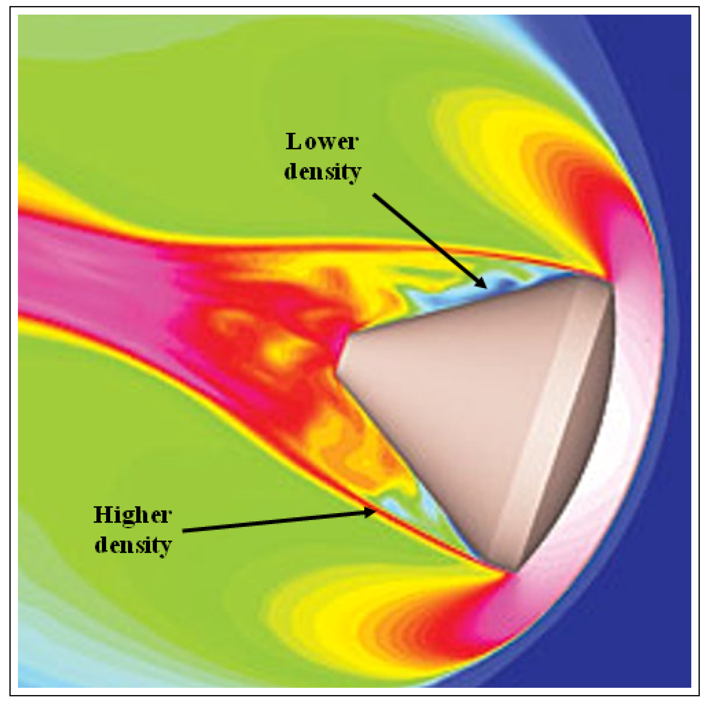
The presence of a plasma layer causes attenuation of the electromagnetic signals propagating through it. These signals are associated with a variety of radio frequency (RF) systems such as voice communications, telemetry, and global positioning system (GPS) data. The attenuation increases as the thickness and density of the plasma surrounding the reentry vehicle increases. An illustration of the plasma sheath surrounding a reentry vehicle is given in Figure 1. Regions of lower and higher plasma density near the vehicle are indicated. The associated effects can become so severe that complete loss of voice communications and even GPS acquisition can occur.
This RF blackout can last anywhere from 90 s to 10 min depending on the trajectory and velocity of the reentry vehicle [3]. It has had severe consequences, for example, in the unmanned Genesis mission to collect samples of solar winds. During reentry of the capsule, a sensor failure caused a parachute to not deploy. If mission control had been in contact with it, a backup parachute could have been deployed to avoid the capsule from crashing into the Utah desert [4]. Similarly, hypersonic flight has been pursued with both manned and un-manned vehicles since 1961, e.g., with the X-15 hypersonic airplane which flew at Mach 6.7 using only rockets [5]. As with the space vehicle reentry scenario, sustained hypersonic flight also faces the potential loss of communications, telemetry and GPS signals. Renewed interest in the RF blackout issue has arisen from the resurgence in interest into hypersonic delivery systems. Consequently, a reasonable solution to the RF blackout problem would greatly increase the chance of mission success for both space missions and hypersonic vehicular technologies.
Many approaches to ameliorate the RF blackout problem have been tried with varying degrees of success [3]. Specifically, remote antenna assemblies [6], which use antennas placed on sharp slender probes ahead of the plasma sheath of a blunt-nosed vehicle; magnetic windows [7], which require generation of powerful magnetic fields; and the addition of quenchants to reduce the electron density [8] or change chemical reaction rates [9]. Implementing one or a combination of solutions may be the most appropriate path forward, depending on the application. System designers will need to evaluate all approaches as research continues to develop and explore new options. The focus in this paper is on a purely electromagnetics-based approach.
An artificial medium, the bed of nails or wire medium [10], was created to study this plasma-related communications problem during the early stages of the Mercury-Gemini-Apollo space program in the 1960s. As will be described in Section 2, the electron plasma acts as an epsilon-negative (ENG) medium for frequencies below its plasma frequency. It will be modeled as a Drude medium, and its electromagnetic attenuation and reflection mechanisms will be explained with it. This wire medium was popularized in the early stages of the birth of metamaterials [11], and is now often recognized from the first reports of negative index [12] and negative refraction [13]. A matching mu-negative metasurface based on split-ring resonator (SRR) elements will be introduced in Section 3. It is related to the SRR-based bulk metamaterial designed for artificial magnetic conductor (AMC) applications [14]. As discussed in [15,16], an appropriate pairing of a MNG metamaterial layer with an ENG one leads to an effective medium through which electromagnetic waves will propagate. The developed MNG metasurfaces are loaded with varactors to enable an adjustable resonance frequency that can be matched to an ENG (plasma) medium with a specific permittivity value. It will be demonstrated that these SRR-based metasurfaces can be tuned to maximize the field transmission through the resulting MNG-ENG plasma layered medium. Finally, the propagation of signals through the MNG-ENG plasma effective medium will be modeled with the fields radiated by both dipole and Huygens dipole antennas in Section 4. It will be demonstrated that the transmitted signal strength and cardioid-shaped pattern associated with the Huygens dipole antenna is an efficacious solution to the RF blackout problem. This metamterial-inspired answer to a long-standing practical issue associated with reentry and hypersonic vehicles will be summarized in Section 5.

2. Electron Plasmas as ENG Media

To properly introduce the Drude model of the permittivity of a lossy electron plasma, several parameters need to be defined. With the Drude model in hand, it is straightforward to understand the impact of an ENG medium on wave propagation in it.

Plasma Parameters

The plasma frequency is a principal characteristic of a plasma; it depends on its density. It is defined as
ω p 2 = n e q 2 m e ε 0
where ω p is the angular plasma frequency in rad/s, n e is the electron density per unit volume, q is the charge of an electron, m e is the mass of an electron, and ε o is the permittivity of free space. Clearly, the plasma frequency increases as the density does.
Another principal characteristic of a plasma is its collision frequency:
ν 2 ω p 4 64 π n e ( k b T m e ) 3 / 2 ln ( Λ ) ( Hz )
where k b is Boltzmann’s constant, T is temperature in Kelvin, and ln ( Λ ) is the Coulomb logarithm, which is typically 10 < ln ( Λ ) < 30 . The value of ln ( Λ ) generally only varies by a factor of 2 over many orders of magnitude of plasma densities. Losses in a plasma result primarily from particle collisions, and therefore the collision frequency is used to characterize them. The Coulomb logarithm is the factor that indicates when small-angle collisions are more effective than large-angle ones. It is reasonable to assume ln ( Λ ) = 10 for a laboratory plasma and ln ( Λ ) = 20 for a reentry plasma [17].
A plot of both the plasma and collision frequencies as functions of the plasma density is given in Figure 2, assuming the Coulomb logarithm is equal to 20 for a fully ionized gas. This plot is an example of the behavior of the plasma and collision frequencies versus the electron density of the plasma. It shows that there is an initial peak in the collision frequency. However, it also indicates that above a density of about 9 × 10 21 m 3 , the collision frequency begins to decrease. This feature is associated with the fact that as the temperature of the plasma continues to increase, the majority of the atoms creating it become ionized and then the temperature dominates the value of the collision frequency, causing it to decrease. The actual location of the collision frequency peak as well as the values of the plasma and collision frequencies will vary depending on the parameters of the reentry environment, e.g., the pressure, air density and composition, etc., but the relative behaviors of the plasma and collision frequencies always follow the pattern illustrated in Figure 2. The plasma and collision frequencies are both used to define the Drude model of the plasma’s permittivity.

3. Drude Model

The Lorentz model of the polarization field, P , in a dielectric represents its response to the presence of an electromagnetic field in it. It is a second order differential equation that is synonymous with the damped simple harmonic oscillator model of a spring or the model of a RLC circuit. It is given by Equation (3) [16,18].
m e 2 t 2 P + m e Γ e t P + m e ω 0 2 P = q E
where Γ is the damping rate, ω 0 is the resonance frequency, and E is the exciting electric field. Because of the difference in mass of an electron and a nucleus, this model of the wave–matter interaction principally describes the motion of the electrons. The resonance frequency is associated primarily with the restoring (attractive) force of the nucleus; the damping rate is associated with all of the interactions between an atom’s constituents.
The Lorentz model reduces to the Drude model when the restoring force is negligible in comparison to the driving force of the electromagnetic field. Therefore, the Drude model is applicable in cases where the material has a large amount of free electrons, such as metal or plasma. Assuming the engineering time convention exp ( j ω t ) , the time harmonic form of the Drude model describes the relative permittivity of a plasma as [16]
ε r ( ω ) = ε ( ω ) ε 0 = 1 + ω p 2 ω 2 + j ω Γ e
where the damping rate Γ e takes the role of the plasma collision frequency and represents the losses. It is clear that in the case of a lossless Drude medium, Equation (4) tells us that ε r ( ω ) < 0 when ω < ω p . Thus, a low loss plasma essentially acts as an ENG medium when an electromagnetic field is propagating in it when the source frequency ω is smaller than the plasma frequency ω p . Consequently, the plasma acts as an ENG medium depending on its density through ω p and Γ e , and the field interacting with it.
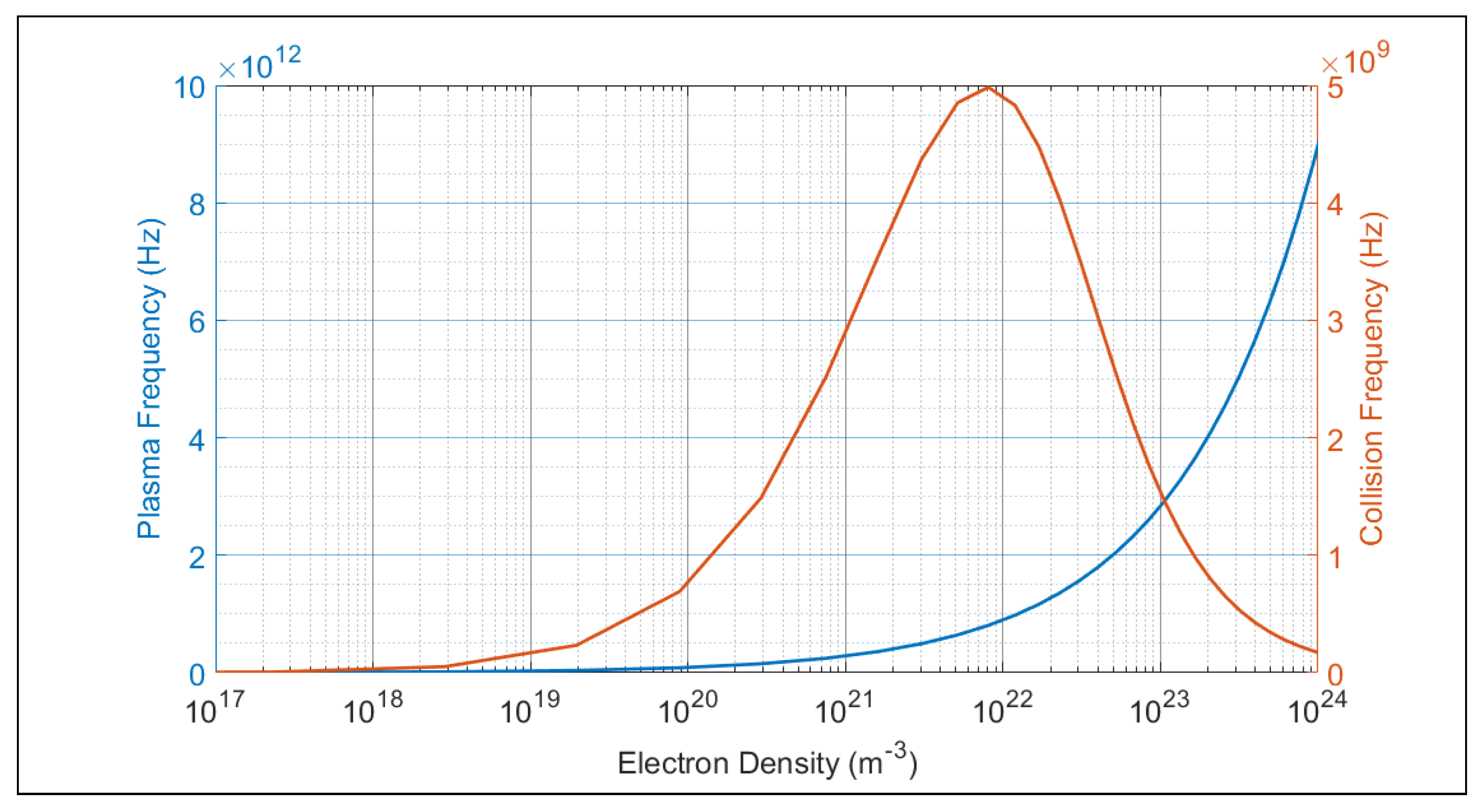
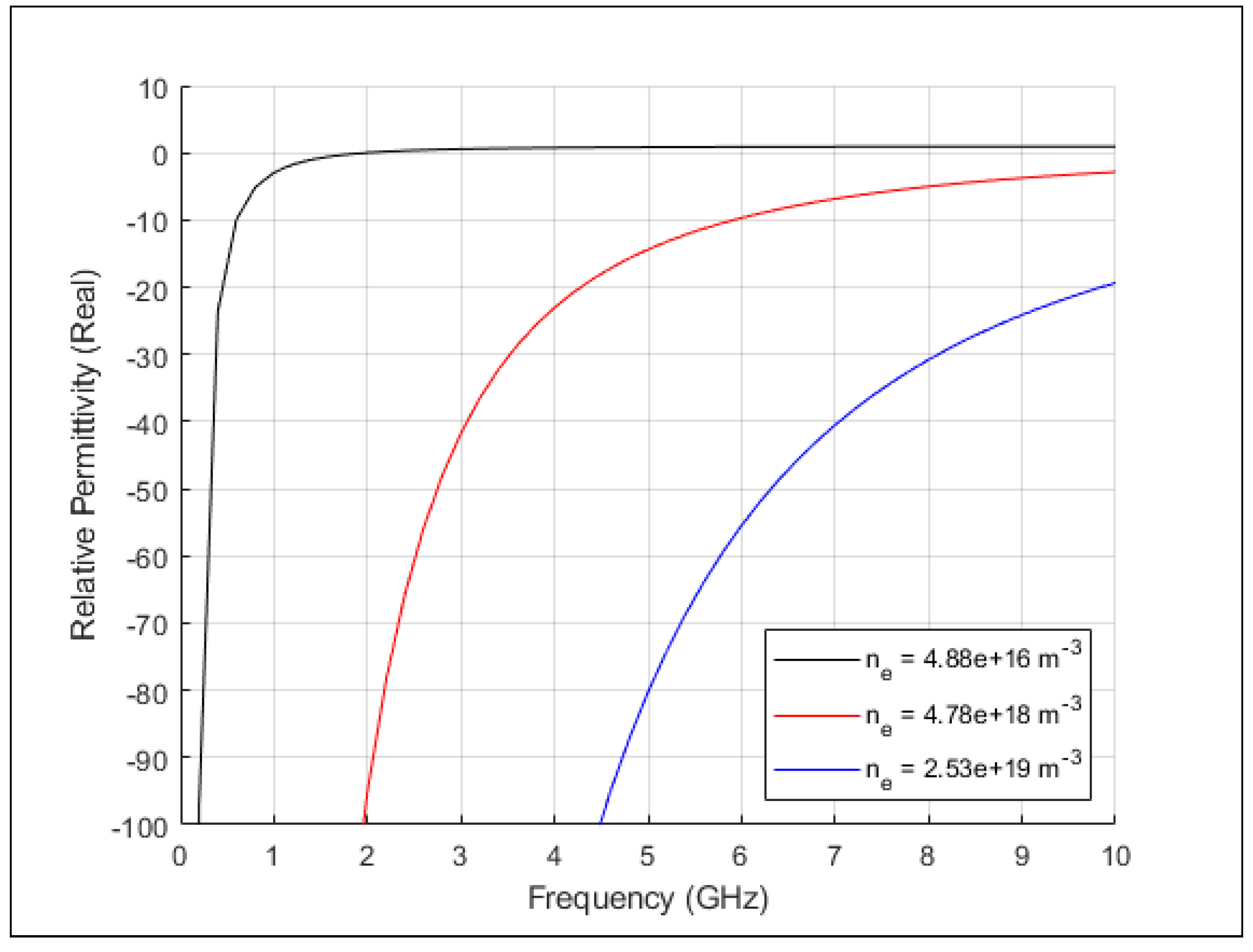
Assuming the electron density is known, the plasma and collision frequencies can be calculated. The real part of the relative permittivity versus frequency can then be computed from Equation (4). The result is the plot given in Figure 3 with the electron density and the source frequency as the two independent axes. The real part of the permittivity is negative at low frequencies when the electron density is small. As the electron density increases, the negative region of the real permittivity extends into higher frequencies.

Wave Propagation in Complex Media

Wave propagation within a material can be understood through the solutions of the equation [19]:
( 2 γ 2 ) Ψ = 0
where Ψ can be either the electric or magnetic field, and γ is the complex constant:
γ = α + j β
where α is the attenuation constant and β is the propagation constant. Solutions of the one-dimensional version of Equation (5) taken, for example, along the positive z-axis that are not growing are simply Ψ = A exp ( γ z ) = A exp ( α z ) exp ( j β z ) , where A is a complex constant. Traveling (evanescent) wave solutions of Equation (5) are defined as solutions whose propagation constant β is real (imaginary). Evanescent waves are then simply decaying within the material.
From Maxwell’s equations it is well-known that β = ω μ ε . Consequently, an ENG medium, i.e., a medium in which μ > 0 and ε < 0 , has β = j ξ , where ξ is a real number, and thus has only decaying fields in it. Similarly, a MNG medium, i.e., a medium in which μ < 0 and ε > 0 , also has β = j ξ and similarly has only decaying fields in it. On the other hand, both a double positive (DPS) medium, i.e., a medium in which μ > 0 and ε > 0 so that β = + ω | μ | | ε | is real, and a double negative (DNG) medium, i.e., a medium in which μ < 0 and ε < 0 so that β = ω | μ | | ε | is real, have propagating fields in them [16]. Therefore, as the permittivity in a plasma becomes negative when a wave whose frequency is below the plasma frequency interacts with it, β is imaginary in it and the corresponding waves are evanescent. Consequently, a plasma only allows evanescent waves at those frequencies, and an electromagnetic signal in it will be attenuated. These features have been verified experimentally by NASA [20].

4. MNG-ENG Layered Structure

To explore overcoming the attenuation associated with the ENG nature of the reentry plasma, a MNG layer is introduced between the electromagnetic radiator and the plasma region. The combined MNG-ENG layers act as a DNG medium, allowing wave propagation through it. Tuning the MNG layer to match the ENG one enhances the overall transmission level.

4.1. Tunable MNG Medium

In 1999, Pendry et al. reported a way to create, by design, an artificial media that acts with a negative permeability [21]. The MNG effect was achieved using highly sub-wavelength resonant structures, i.e., split-ring resonators (SRRs), as inclusions in a dielectric background. The SRRs work by creating small loop currents when an incident magnetic field is correctly oriented to create flux through them or an incident electric field is parallel to its face and drives the current directly. The resulting loop current acts as a magnetic dipole, affecting the material’s permeability in a manner similar to an electric dipole affecting the material’s permittivity. It was recognized that a non-resonant closed loop produces a much smaller response than the resonant open one. The SRR can be designed for a desired operating frequency. The capacitances between its two split rings and in the gaps of each ring along with the inductances of each split ring act as a resonant L-C element, whose resonance frequency can be tuned by design. When many split rings are combined in a planar or volumetric array, they can be arranged to act coherently to yield a negative permeability above the resonance frequency as shown in Figure 4.
The layout of a C-band SRR is shown in Figure 5. The metallized rings combine to give the effective inductance L s . All of the gaps combine to yield the effective capacitance C s . The resulting LC tank circuit has the resonance frequency: f 0 = L s C s / 2 π [22]. Introducing a varactor across both of the open gaps of the split rings facilitates the realization of a total capacitance that is tunable. Consequently, the resonant response of the SRR-based metamaterial permeability is tunable.

4.2. Wave Propagation through the MNG-ENG 2-Layered Structure

As simulated in [15], it is possible to build a DNG material by combining alternating layers of MNG and ENG materials. Care must be taken to establish a match between the ENG and MNG regions in order to maximize the transmission through their combination. The ENG medium is assumed to be lossless to simplify the discussion. It became evident while studying the reentry plasma scenarios that the plasma density, and therefore the relative permittivity of the ENG region changes, over the reentry trajectory as the temperature near the exterior of the vehicle increases. Therefore, to maintain matching with a plasma whose permittivity is changing, it becomes desirable to have the resonance of the permeability of the MNG layer be tunable to move the negative region into the frequency range of the negative permittivity. Hence, a tunable SRR-based metasurface is needed.
The ability of the tunable SRR-based MNG layer to be matched to the plasma’s ENG response is demonstrated by studying two cases in which the same SRR design is used to match the SRR-based negative permeability to the plasma’s negative permittivity simply by changing the voltages applied to the varactors. The response of an infinite layer of the SRR unit cells in Figure 5 on a 1.0 mm thick RogersTM 5880 material whose relative permittivity is ε r = 2.2 and whose loss tangent tan δ = 0.009 combined with a 1.0 mm thick bulk ENG material representing the plasma layer was simulated for a normally incident electromagnetic wave. The simulations were performed in CST Microwave Studio (MWS) using a unit cell configuration, i.e., perfect electric and magnetic boundaries were introduced in the x- and y-directions to yield a normally incident, x-polarized plane wave. Ports were implemented at both of the surfaces with z-directed normals. The phase reference plane for each port was adjusted to the corresponding nearest surface of the two-layered material to attain the correct reflection and transmission coefficients. The geometry of the CST model is shown in Figure 6.
The adjustable capacitance in the CST model was added as a discrete component in the SRR gaps as shown in Figure 6. Both cases of the electric field being oriented across the SRR gaps (parallel to the varactor orientation) and orthogonal to it were simulated. Only the former (parallel) case induces the desired resonant currents in the SRRs whose resonance frequency can be tuned by adjusting the varactors’ effective capacitance.
The simulated S-parameter results for the parallel case are given in Figure 7 and Figure 8. They show a narrow nearly-complete passband response that depends on both the ENG permittivity and the SRR’s capacitance. The variation in the S-parameters as the ENG material’s permittivity becomes more negative while the resonance of the effective permeability is fixed at 4.4 GHz is displayed in Figure 7. The maximum transmission loss for each case is −0.32 dB at 4.47 GHz when ε = 2.0 , −0.36 dB at 5.02 GHz when ε = 4.0 , and −0.38 dB at 5.20 GHz when ε = 6.0 . These results show that the passband moves up in frequency as the plasma frequency increases, i.e., the permittivity becomes more negative in the targeted C-band. On the other hand, Figure 8 illustrates that as the SRR capacitance is increased with the plasma frequency fixed at 8.838 GHz and the collision frequency fixed at 300 MHz, the resonance frequency of the MNG layer decreases, i.e., the passband moves down in frequency. The maximum transmission loss for each case is −0.40 dB at 5.22 GHz for 1.0 pF, −0.38 dB at 4.79 GHz for 2.0 pF, and −0.37 dB at 4.54 GHz at 4.0 pF. The −3 dB bandwidths of the passbands are all approximately 360 MHz, a 7.2% fractional bandwidth at 5.0 GHz. Both results illustrate that the MNG-ENG two layered medium supports a nearly complete, finite passband that can be tuned to a desired frequency.
It is also noted that as considered here, the MNG layer would have to be integrated into the surface of the reentry vehicle or airframe as it is the interface with the plasma. Consequently, its SRRs and embedded varactors would necessarily have to be on the interior side of it. Moreover, a metal-clad ceramic material, which can readily survive the indicated temperatures, would have to replace the Duroid substrate from a practical point of view. The SRR-based design is very amenable to the modifications that would be necessary to accommodate these practical considerations.

4.3. Propagation Losses through a Plasma

The loss experienced by a wave propagating in the plasma region can be calculated with the imaginary part of the permittivity in Equation (4), i.e.,
Im [ ϵ r ( ω ) ] = j [ ω p 2 / ( Γ e ω ) 1 + ( ω / Γ e ) 2 ]
As expected, the plasma frequency (Equation (1)) figures prominently in the calculation. The collision frequency Γ e is generally at least an order of magnitude smaller than the plasma frequency as seen in Figure 2. As the plasma frequency is determined from the electron density, the plasma losses are directly proportional to the plasma density. However, the plasma density varies greatly depending on the airframe and the speed and angle of reentry [23].
The predicted electron density can vary dramatically from near the capsule’s or airframe’s surface to the surrounding plasma sheath to the region beyond as has been reported in a variety of works [24,25,26,27]. For our studies, an electron density of 10 18 m 3 was chosen as a reasonable intermediate value. This choice results in a plasma frequency of 8.927 GHz. A plasma temperature of 2000 K is chosen for Equation (2) which results in a 42.5 MHz collision frequency. This temperature choice is not necessarily indicative of the maximum temperature of a reentry plasma, but rather an average temperature seen along the path of the electromagnetic wave traveling through the plasma. The basis for this choice can be understood from Figure 1. The intense plasma formed by the shock wave associated with the “heat shield” portion of the reentry capsule or the nosecone at the front of an airframe can reach temperatures exceeding 10,000 K. However, knowing the expected characteristics of the vehicle’s atmospheric trajectory, any communications or GPS antenna would be placed away from those hot-spot regions, i.e., these antennas would be placed in the indicated “lower density” region near it. Thus, the indicated plasma temperature is then a highly reasonable value. The resulting collision frequency and attenuation values also are consistent with previous studies of the reentry plasma [28]. The values associated with these choices give ϵ r = 2.06 + j 0.026 at the 5.1 GHz operating frequency. The real part of ϵ r is rounded down to −2.0 in order to simplify the ensuing discussion.
To explore the magnitude of the propagation losses in such a plasma as a function of its thickness, an analytical one-dimensional multi-layer model was developed and modeled with the transfer matrix method (TMM) [29] implemented in MATLAB. The multilayer model is shown in Figure 9a. Regions 1 and 4 are free space. Region 2 represents the MNG layer and Region 3 represents the ENG layer, i.e., the plasma. As a representative example, consider the relative permeability value of the MNG layer to be chosen to be a conjugate match to the ENG layer as described in [15]. In particular, setting μ 1 r = μ 2 r , ϵ 1 r = ϵ 2 r , and d 1 = d 2 = 1.0 mm, the TMM code calculated S-parameter results as a functions of the frequency are shown in Figure 9b. They clearly indicate that little to no reflection and nearly complete transmission occurs for this matched case near the operating frequency, 5.1 GHz. Thus, the attenuation of the fields radiated by an antenna in Region 1 that would be accumulated after propagating through this structure, i.e., as they reach the output face of Region 3 and enter the free-space Region 4, would be due primarily to the attenuation they experienced after passing the 1.0 mm depth as they propagated through the plasma region.
Using the TMM model further, the thickness of the ENG (plasma) layer was varied from 1.0 mm to 100 mm (10.0 cm), while leaving the MNG layer at the designed 1.0 mm thickness. To verify these TMM results and to confirm the efficacy of the CST software for this class of problems, simulations of the same problems were compared. The CST S-parameter data was imported into MATLAB and the differences with the TMM data were calculated. Both lossless and lossy plasma cases were studied. Both cases were simulated with the real part of the permittivity being Re [ ϵ r ] = 2.0 . Both lossy cases were simulated with the corresponding conductivity [18]:
σ = ε o ω p 2 / Γ 1 + ω 2 / Γ 2
i.e., with σ = 0.073 S/m.
The TMM-calculated transmission coefficient results as a function of the thickness of the plasma are shown in Figure 10a. Figure 10b shows the difference in dB between the TMM and CST results. These differences are quite small. The maximum difference is in the lossy plasma case, being 0.15 dB, which is well within acceptable limits for the discretization level used in the CST simulations.
The exponential loss shown in Figure 10a varies from 0.004 to −124 dB. However, in a very dynamic environment such as atmospheric reentry, the losses typically reach a maximum of about −40 dB because of the variations in the plasma density in the sheath [23,28]. With further simulations, the attenuation realized simply by the evanescent nature of the fields as they propagate beyond the matched distance dominate the losses. The additional loss associated with taking into account the loss term Im [ ϵ r ] in Region 3 is shown in Figure 11. It is insignificant in comparison to the evanescent decay associated with the imaginary part of the wave number in the plasma and thus will be ignored for the remaining aspects of this study.

5. Antenna Performance in the Presence of the 2-Layer MNG-ENG Structure

The unit cell (i.e., the planar, periodic, transversely infinite) simulations demonstrated the proof of concept that a MNG-based metasurface can be designed to enable a passband in the presence of an electron plasma (i.e., an ENG medium). As an antenna on a reentry or hypersonic vehicle is ideally positioned within rather than on the structure for aerodynamic and structural integrity purposes, the MNG metasurface would be integrated as a window in the surface of the vehicle with the application antenna being located behind it relative to the exterior. Thus, simulations of the response of an antenna radiating in free space from the MNG side of the MNG-ENG structure were performed. The results demonstrate that the antenna–MNG metastructure can be designed to achieve application-significant transmission through the ENG-based plasma, e.g., for communications purposes.

5.1. Dipole Performance

Simulations with an idealized electrically small dipole antenna first illustrate this concept. The standard dipole antenna pattern is well known [30]. The peak gain is 1.76 dBi. 
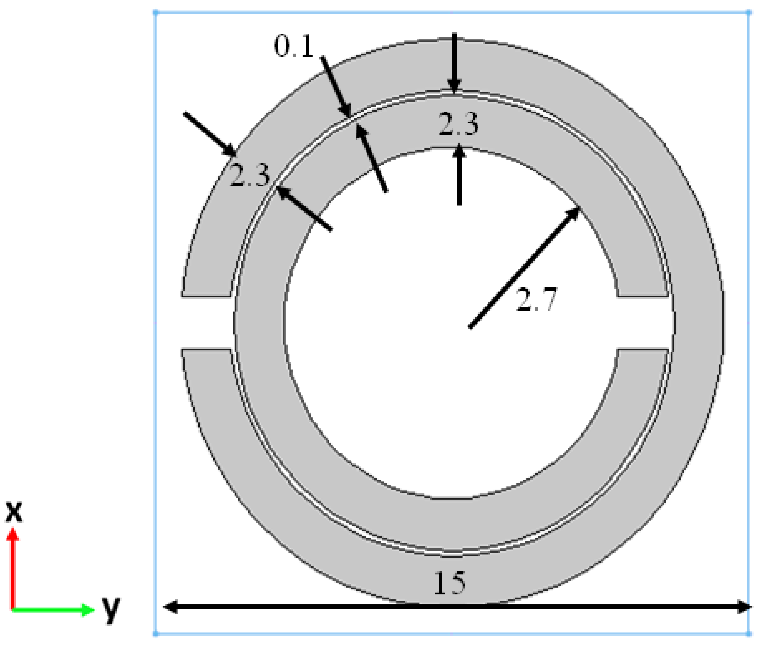
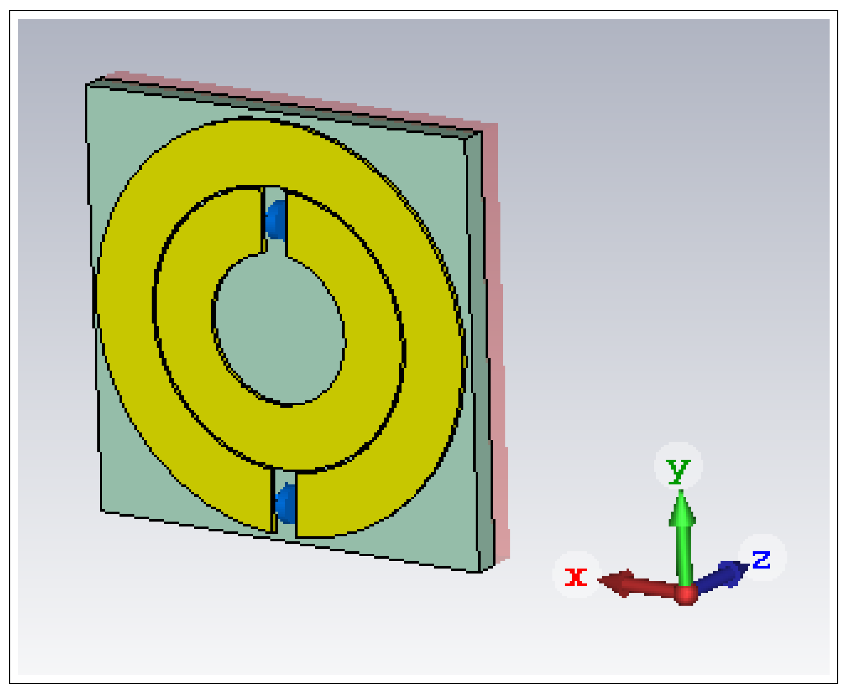
Figure 12 shows the simulation model in the presence of the two-layer metastructure. A finite-sized MNG-based metasurface that consists of nine SRR unit cells is introduced on the antenna side of the ENG (plasma) layer. The thicknesses of the Duroid substrate and the plasma region were again fixed at 1.0 mm. The dipole antenna is centered along the y-axis at the origin and has the total length 11.8 mm. The dipole was implemented using 0.6 mm diameter cylinders with a 2.0 mm gap between them driven by a 50 Ω discrete port. The finite-sized SRR material is located 10.0 mm away ( λ / 5.88 at 5.1 GHz, slightly beyond the reactive near field of the dipole, λ / 2 π ). This offset distance from the metasurface is sufficient for this short dipole to effectively illuminate a significant portion of it directly, exciting its steady state MNG response. Note that the ENG material is located on the free space side opposite to that of the antenna as it would be for the reentry scenario. Also note that the linearly polarized dipole antenna is oriented along the x-axis. Consequently, its broadside electric field is also oriented along the x-axis, which is the optimal configuration, i.e., the electric field is oriented across the gaps of the two split rings in each SRR element to maximize the response of the metasurface.
The ENG region’s relative permittivity was set at ε r = 2.0 and its relative permeability was set at μ r = 1.0 
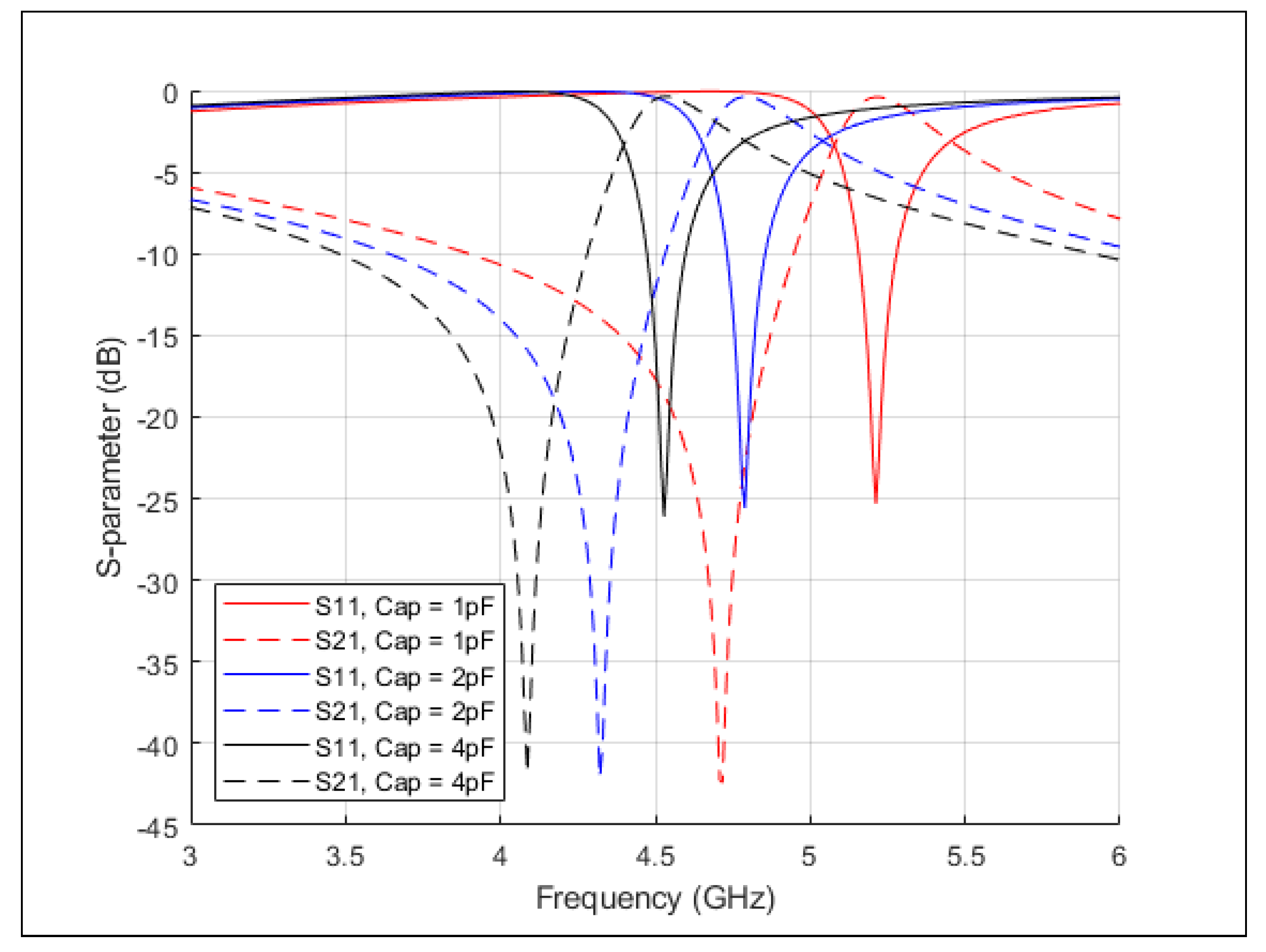
. The unit cell design of the MNG metasurface was the same as the infinite periodic case; it was matched to the ENG region to obtain the passband at 5.1 GHz shown in Figure 7 by specifying the capacitance value to be 1.0 pF. Because the metasurface is now finite in size, the actual transmission values are not identical to the infinite periodic case. Any reflection or absorption effects associated with this fact will now be exposed with comparisons of the far-field performance characteristics of the antenna in free space and in the presence of the layered MNG-ENG metastructure.
The far-field directivities of the dipole in its E- and H-planes are presented in the Figure 13. Its frequency, 5.1 GHz, is matched to the passband of the MNG-ENG structure. Moreover, the size of the dipole is small relative to the overall size of the metasurface as is its distance from it. Consequently, there is very little leakage of the radiated field diffracted around it. The dipole was artificially matched to its idealized source to yield its best performance. The maximum directivity in the “exterior” (“interior”) free space region shown in the E-plane in Figure 13a is 4.07 dBi (4.45 dBi) in the broadside +z (-z) direction. The higher than free-space broadside directivity in the ϕ = 0 plane is an immediate consequence of the significant narrowing of the field pattern brought about by the inherent enhanced response of the metastructure to the x-directed electric field. On the other hand, the expected omnidirectional directivity pattern in the H-plane in Figure 13b only shows a bit of distortion along the y-directions. This distortion is the direct result of the magnetic fields of the finite-sized dipole, which are no longer parallel to the metasurface but rather, are obliquely incident on it. Thus, they impact the performance of the SRR elements, which in fact have a bi-anisotropic response. Nonetheless, the results demonstrate that the effective DNG metastructure does provide an passband window for signals radiated by the dipole antenna. Nevertheless, the dipole itself, being a bidirectional radiator, directs slightly more than half of its radiated power into the source region. In particular, the realized gain in the broadside, +z-direction is 2.48 dBi and is 2.85 dBi in the -z-direction.

5.2. Huygens Design Performance

Ultimately, a unidirectional antenna is highly desired for any “sub-exterior surface” antenna system. The electrically small Huygens dipole antennas developed in [31,32,33,34] are advantageous in this regard. The linearly-polarized Huygens antenna is made up of three major components: a capacitively loaded loop (CLL), an Egyptian axe dipole (EAD), and a smaller dipole that excites these near-field resonant parasitic (NFRP) elements by coupling energy into them. In free space they are electrically small systems that radiate a broad beamwidth, unidirectional cardioid pattern with basically a 3 dB peak directivity enhancement over that of an equivalent sized dipole antenna. The Huygens design in [
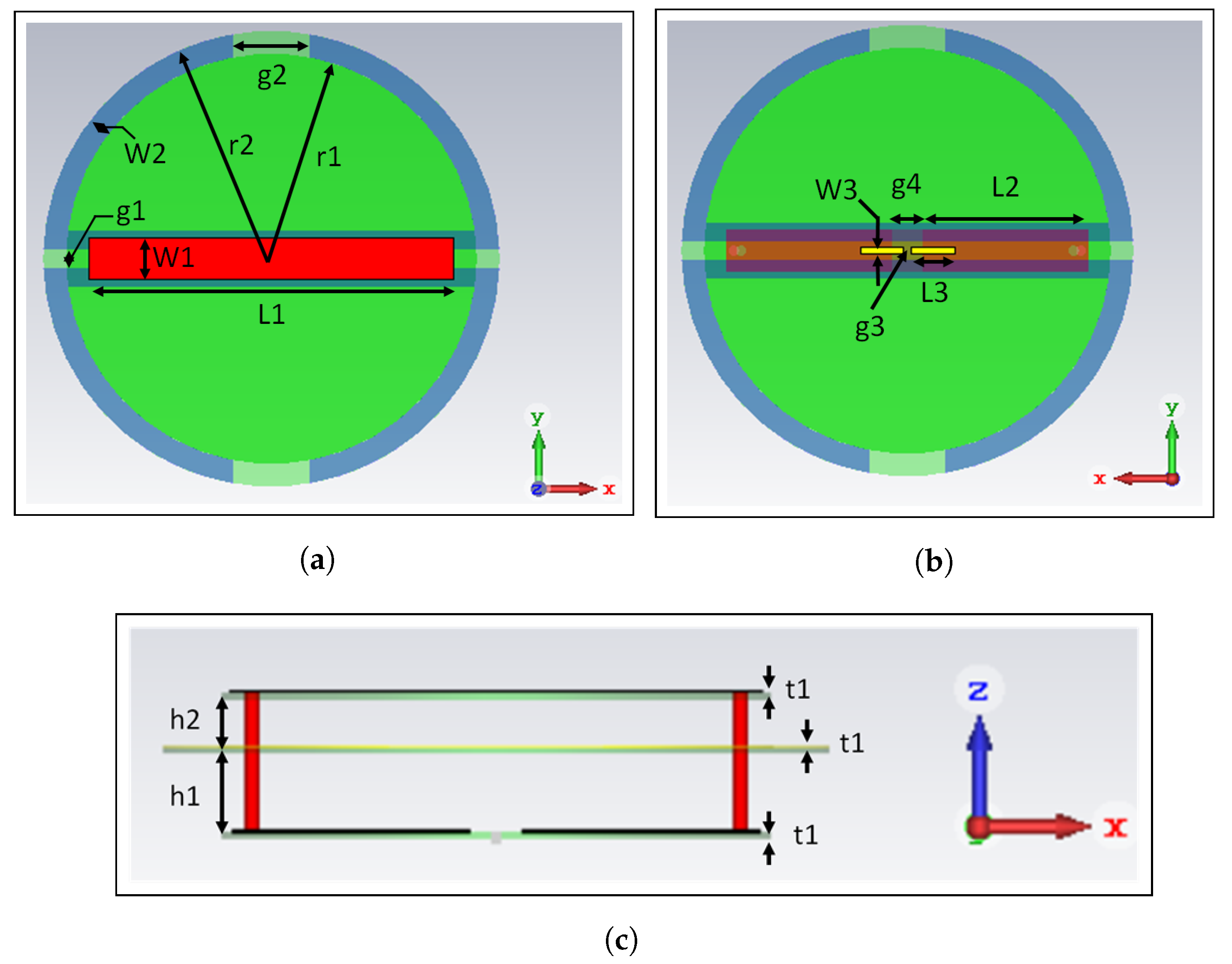
31] was modified to have the same operating frequency as that of the dipole case, 5.1 GHz. The modified design is shown in Figure 14, and the design parameters are shown in Table 1.
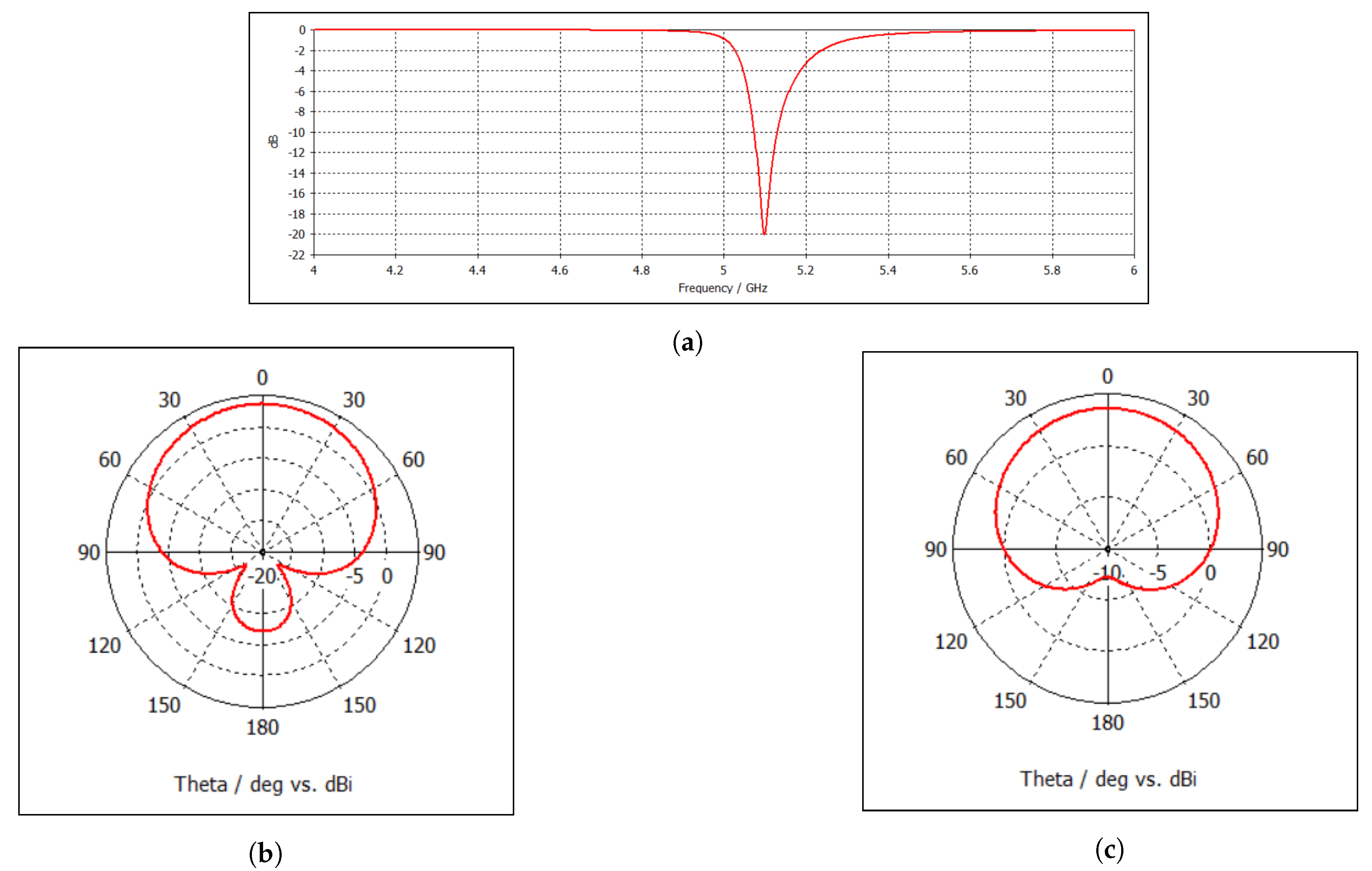
Its performance was verified first in free space. The CST simulation results are shown in Figure 15. The cardioid nature of the patterns is immediately recognized. The peak directivity, 4.15 dBi, at 5.1 GHz is in the broadside +z direction; the corresponding front-to-back ratio (FTBR) is 10.9 dB. The corresponding peak realized gain value is 3.58 dBi. The associated minimum FTBR is 10.9 dB. The radiation efficiency is 88.6%.
The same MNG-ENG metastructure used in the dipole case was then introduced. As the Huygens antenna is also linearly polarized, it was also oriented with its electric NFRP element oriented along the x-axis as shown in Figure 14a to maximize the response of the MNG metasurface. Moreover, as with the dipole antenna, it was located 10 mm from the front surface of the MNG layer.
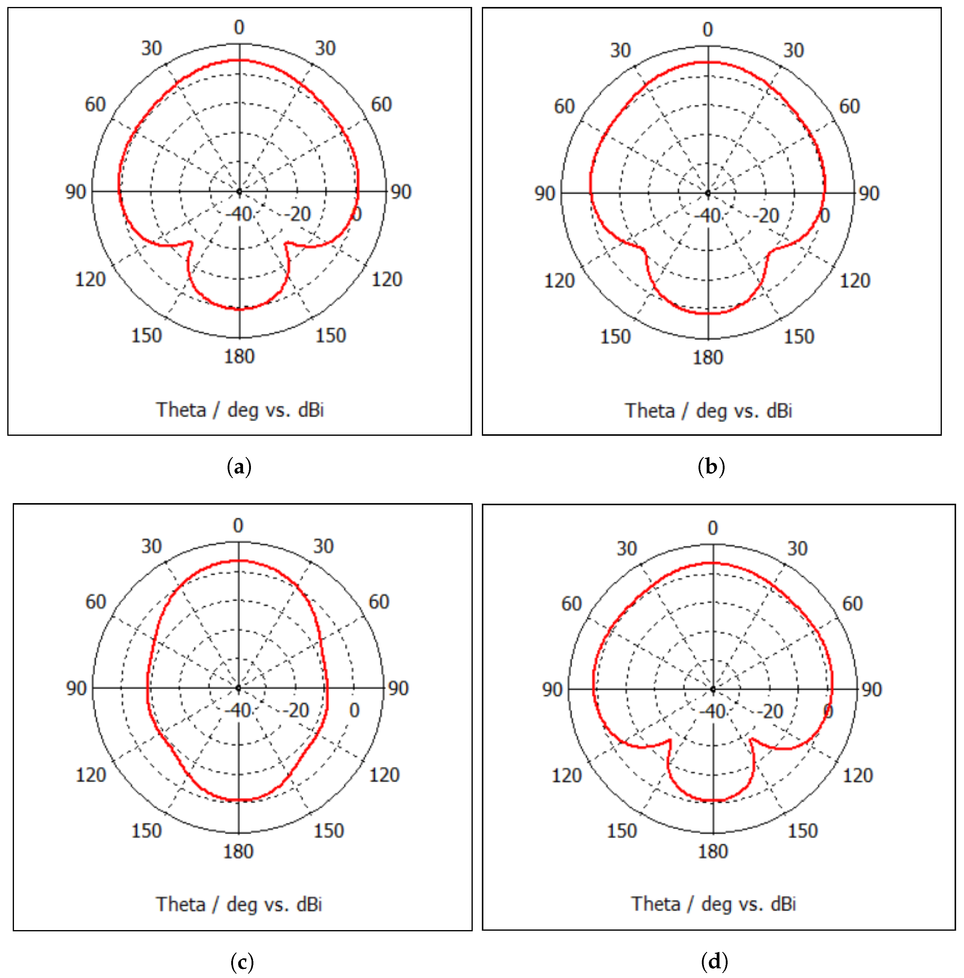
The corresponding realized gain patterns in the two principal planes, ϕ = 0 and ϕ = 90 , at 5.1 GHz of the Huygens dipole antenna in the presence of the MNG-ENG layered metastructure with ε r = −2.0 in the plasma layer and the capacitor = 1.0 pF to attain the MNG layer with μ r = 2.0 , are shown in Figure 16a. The peak directivity, 5.87 dBi, at 5.1 GHz remains in the broadside +z direction; the corresponding FTBR is 4.7 dB. The associated peak realized gain in the +z-direction is 3.40 dBi, and the radiation efficiency is 92.9%.
Note that the cardioid nature of the patterns is distorted from their free space shape but its resemblance is still recognizable. The MNG-ENG structure has unbalanced the relative electric and magnetic dipole responses of the free-space Huygens design. Nevertheless, the results clearly demonstrate that significant field levels are radiated into the exterior, free space region. In fact, these results compare favorably with the free space ones. They clearly demonstrate that the combination of the metastructure and a Huygens dipole antenna could potentially be successful in mitigating the plasma blackout problem.
Moreover, note that there was an unexpected directivity improvement in the +z-direction along with some narrowing in the patterns in both the ϕ = 0 and ϕ = 90 planes. It is associated with the fact that the MNG-ENG pair in this case is a conjugate match. In particular, the MNG-ENG metastructure is nearly transparent at every incident angle. However, due to the anisotropic nature of the SRRs in the realistic MNG layer, its response does vary away from the broadside direction. It was found that this effect actually causes the MNG-ENG metastructure to act as a lens, directing more power into the broadside direction with a corresponding narrowing of the realized gain patterns.
Another consequence of the lensing effect is that the beamwidth in the ϕ = 90 plane can be adjusted at the cost of realized gain by varying the distance between the metastructure and the Huygens dipole antenna. The results of a parameter study of the pattern quality as the distance between the antenna and the metastructure was varied are summarized in Table 2. The general effects are clearly seen in the comparison between the 5.5 mm spacing results shown in Figure 16b and the 10.0 mm spacing results in Figure 16a.
Moving the antenna away from the metastructure narrows the −3 dB beamwidth while increasing the realized gain in the +z direction and generally reducing the associated FTBR value. On the other hand, moving the antenna closer to the metastructure generally broadens the beamwidth while decreasing the realized gain and increasing the FTBR. While the lensing effect is more severe and particularly noticeable in the ϕ = 0 plane, where the SRRs have their strongest response, the beamwidth remains relatively constant between 50 to 60 despite the dramatic visual narrowing of the pattern. It is found that if the antenna is moved too close to the metastructure, the beamwidth in the ϕ = 90 plane becomes much larger than 180 and the FTBR decreases as the overall pattern tends to become essentially fan-like. The 5.5 mm and 7.0 mm spacing choices yield both acceptable realized gain and FTBR values. Comparing the realized gain patterns in Figure 16, the differences in the peak directivity and FTBR features are now understood.

6. Parameter Studies

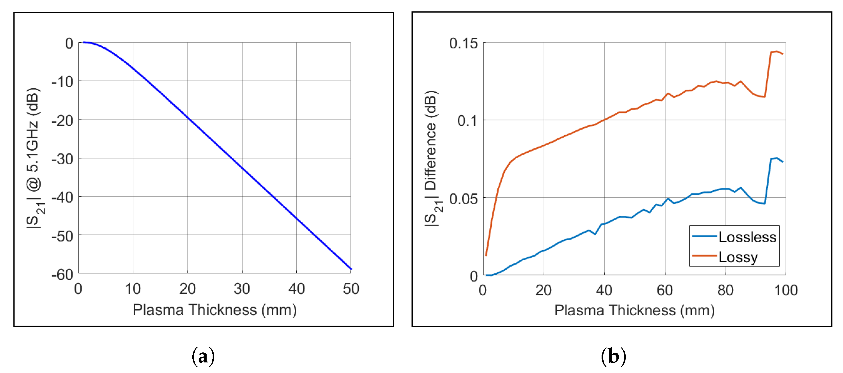
With these very positive directivity results in hand, the thickness of the plasma and its impact on the magnitude of the field radiated past it into free space became yet another interesting issue. Returning to the TMM code, variations of the plasma thickness and incident angle were investigated to understand how the attenuation changes as the incident angle does. The results are shown in Figure 17.
As the plasma thickness increases, the attenuation increases quickly for large off-axis angles. The effect causes the beam to narrow as the plasma thickness increases. This narrowing outcome supports the desire to have a more directive antenna for the application. The previous results for the antenna-MNG layer distance of separation then suggest that this off-axis angle effect might be somewhat counteracted by moving the antenna farther away to increase the resulting directivity and narrowing the beam further. On the other hand, depending on where the receiving antenna is relative to the location of the antenna system in the reentry vehicle, one might want to move the antenna closer to the MNG interface to enhance the probability of receiving the transmitted signal knowing that this separation distance will widen the beamwidth even though an increased attenuation penalty would occur. A system engineering design analysis as to whether or not the position of the antenna should be movable to take advantage of this physics may be advantageous.
As demonstrated in [15], a conjugate match requires that k 1 d 1 = k 2 d 2 or equivalently with μ 1 r = ϵ 2 r d 2 / d 1 for the Region 3 and 4 material properties that we have assumed. Consequently, with the Region 3 permittivity set to ϵ 2 r = 2.0 , this means that if μ 1 is varied linearly with the plasma thickness as μ 1 r = 2 d 2 / d 1 , the conjugate match should be maintained. As the SRR design is frequency tunable, the actual value of | μ 1 | could be increased simply by moving its resonance point closer to the operating frequency.
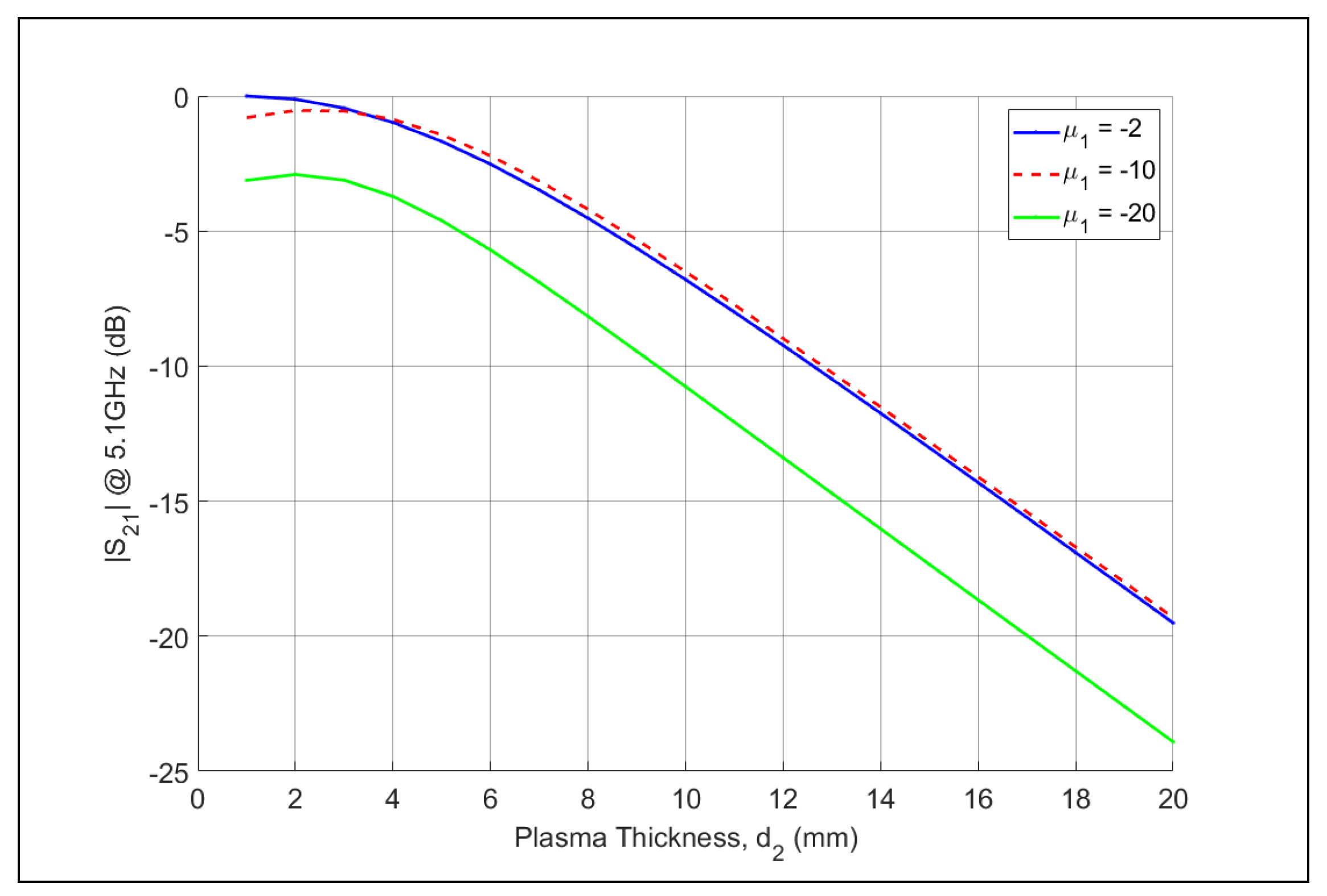
To investigate if there would be any advantage to adjusting its value in anticipation of a particular thickness, the TMM code was used to calculate the attenuation experienced by the fields with the MNG-layer permeability adjusted for the thickness of the plasma. The results obtained by setting d 1 = 1.0 mm and ϵ 2 r = 2.0 are shown in Figure 18 for d 2 again varying from 1.0 to 20.0 mm for three different values of μ 1 r . While they appear to show some slight advantage at further distances, the results actually indicate that the initial level of the field in the plasma region is negatively affected by not matching the plasma next to the vehicle. There is no means to recoup the signal level once it has entered into the plasma region. This result confirms that the best strategy is to match the MNG layer to the permittivity of the ENG layer as it begins.
As discussed in many recent reentry plasma studies [23,
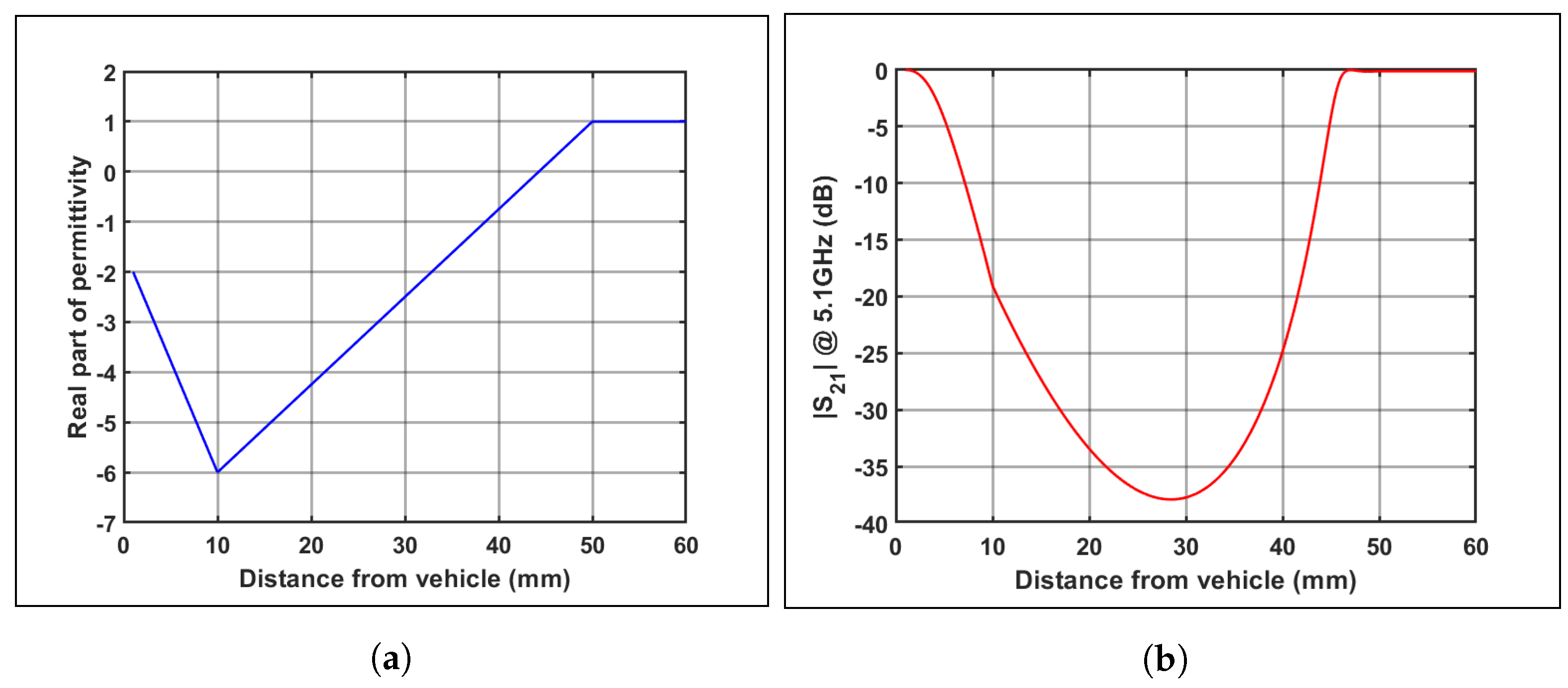
24], the plasma density of the plasma layer is not constant as the distance from the reentry vehicle increases, i.e., the permittivity of the plasma has a profile. As noted above, it depends on many factors such as the actual vehicle shape, its angle of attack entering the atmosphere, and its speed. To understand the impact of the profile on the transmitted signal, the four region problem was considered with the simple profile for Region 3 shown in Figure 19a. The permittivity has ϵ 2 r = −2.0 in the 1.0 mm thick layer at the reentry vehicle’s surface and assumes a plasma density in the sheath that reaches its maximum at 30.0 mm away from it and then reaches free space at a distance of 50.0 mm. The calculated transmission coefficient with μ 1 r = −2.0 is shown in Figure 19b.
The main takeaway from this result is that the attenuation level reaches a maximum value that is just slightly less than −40 dB for this profile and then begins to decrease to zero at the outer boundary of the plasma. As noted above, the signal would thus experience a decrease of around that maximum value. While it seems to be a large decrease, even larger attenuation levels are encountered in existing practical systems. For example, the up and down links for satellite communications to and from the earth experience path losses from 100–200 dB each way depending on the signal frequencies, weather, and satellite altitudes [35,36]. These large propagation losses explain why large reflector antennas with extremely high directivities are required to counteract them in such communication scenarios. Again, the analysis indicates that a proper matching of the permeability of a single MNG layer to the permittivity of the plasma next to the reentry vehicle leads to a potential, practical engineering solution.
Nevertheless, instead of restricting oneself to a single MNG layer that may require a rather large negative permeability value to counteract a high plasma density region next to the vehicle, one could consider replacing the single layer with a multilayer structure that alternates artificially realized ENG and MNG layers [15] until the initial layer of the plasma region is reached to obtain an effective k 1 d 1 value to match the anticipated plasma thickness or negative permittivity value, and therefore its associated larger k 2 d 2 value. In this sense, the plasma layer is always instantiated as the last layer, with the rest of the layers being optimized to provide the conjugate match and the consequent DNG metastructure. This multilayer approach requires the thickness of each layer, d m , for m = 1 , . . . , M , to be less than about 1/8th of the wavelength in each layer, i.e., d m λ source / [ Re n m ] , where n m is the index of refraction in the m-th layer. By changing d m , the multilayer structure can be designed to act as a bandpass filter with the thickness d m determining the center frequency of the filter. This response is well-known; it is what is encountered in one-dimensional periodic structures [37,38] such as Bragg mirrors [39,40].
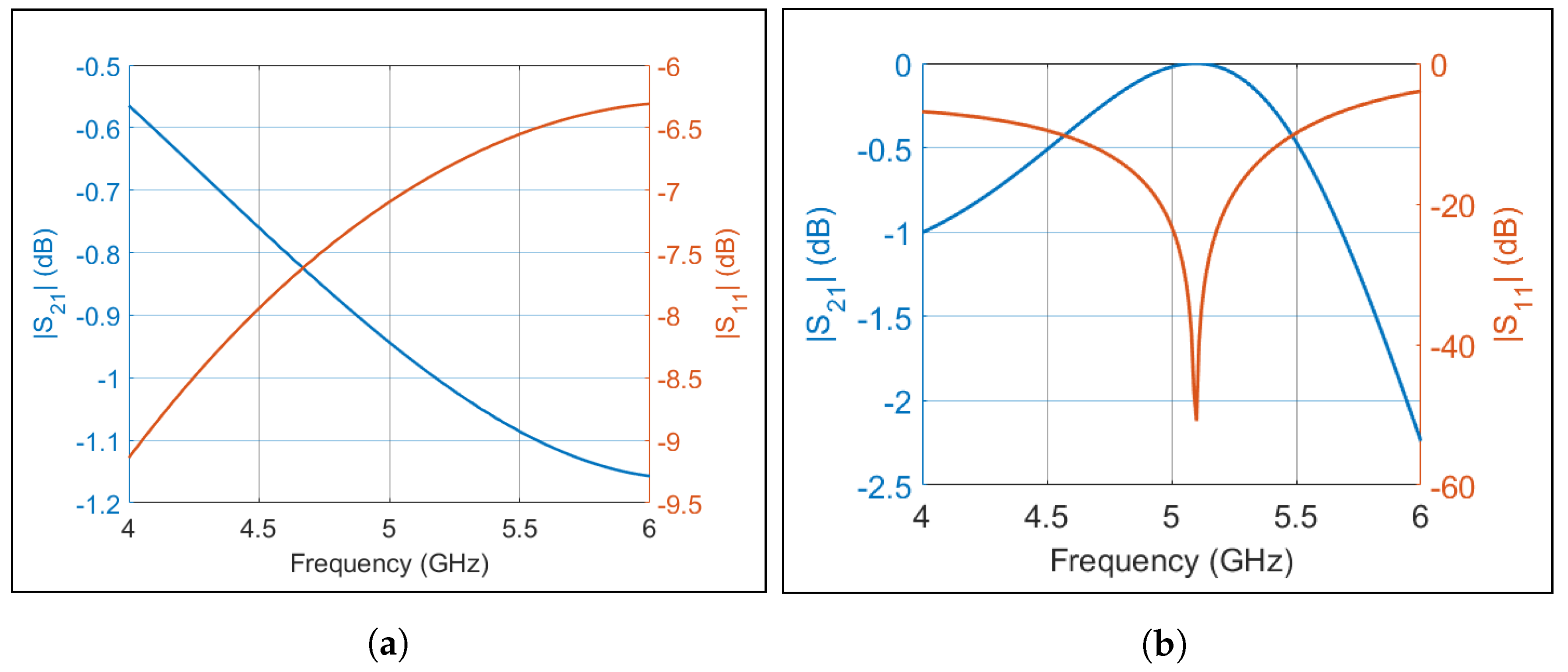
The S-parameters of a representative 10-layer structure of alternating ϵ r = 2.0 and μ r = 2.0 layers for 2 different layer and plasma thicknesses, d m = 3.0 mm 0.072 λ e f f , and d m = 5.23 mm 0.126 λ e f f , where λ e f f = 41.57 mm is the wavelength in each layer at 5.1 GHz, are shown in Figure 20a,b, respectively. The band pass response at the desired operating frequency is clearly obtained in the 5.23 mm case. Note that if the dielectric thickness, d m , was increased much beyond a fifth of the source wavelength, then the dramatic evanescent wave decay shown with the previous two layer cases takes over. Even though its response may become quite narrow in bandwidth because the plasma layer may be thick, by designing the resulting Bragg filter to have its maximum transmission at the desired operating frequency, i.e., to have it tuned to the resonance frequency of the Huygens dipole antenna and completely encompass its narrow bandwidth, a relatively strong signal—even a Morse code signal at a specific frequency—could be inserted into the plasma region with a significant chance of reaching the free space region with strong enough signal strength to establish even rudimentary communications during reentry. Similarly, the narrow bandwidth signal emitted by a GPS satellite could reach a well-placed receiving antenna in the vehicle.

7. Conclusions

The design of a metasurface and a Huygens dipole antenna to facilitate the transmission of signals through a reentry plasma was examined. A 1.0 mm thick SRR-based MNG metasurface was developed whose properties are tunable. It was combined with the plasma layer to form a two-layer MNG-ENG metastructure that produced a passband with very high transmission levels. The DNG properties of this metastructure overcame the deleterious evanescent field behavior when only the ENG plasma layer is present. It was demonstrated with both electrically small dipole and Huygens dipole antennas that significant power could be radiated into the the plasma region with an appropriately configured MNG-ENG metastructure. The MNG-ENG structure was specifically designed to be a conjugate match for the base case with a 1.0 mm thick plasma with ε r = 2.0 next to the reentry vehicle, i.e., the MNG layer was designed to have μ 1 r = 2.0 at the C-band operating frequency, 5.1 GHz. The peak realized gain with the Huygens dipole antenna was up to 2.01 dBi higher than the simple dipole reference case.
Further adaptability of the MNG-ENG metastructure was demonstrated on the basis of the anisotropic nature of the SRRs to facilitate a narrowing of the beamwidth of the radiated fields along the direction orthogonal to the linear polarization direction of the antennas while essentially maintaining a consistent beamwidth, but narrower overall pattern in the parallel direction. Moving the Huygens dipole antenna closer to the metastructure creates a broader beam at the expense of some broadside peak realized gain and vice versa. This feature to narrow or widen the beamwidth could help the applicability of the reported approach. It also could allow the pattern of a single system to transition dynamically between a wide and narrow beamwidth if the position of the antenna was allowed to change physically relative to the metastructure.
Several different properties of the complex media system were explored to understand the level of attenuation a radiated signal would face under different plasma conditions. Both constant and profiled plasma permittivity issues were investigated. The results indicated that the best approach was to conjugately match the MNG layer to the properties of the plasma layer next to the reentry vehicle. While the resulting attenuation corresponding to a plausible plasma profile associated with a reentry scenario was considerable, the maximum level nevertheless was not perceived to be insurmountable in practice.
This work has identified a path to potentially overcome the blackout problem faced by reentry spacecraft and hypersonic aerial vehicles. While the tunable two layer MNG-ENG metastructure was proven to be effective for the assumed plasma thickness, extending the range and properties of the metastructure, such as with the multilayer Bragg filter design to conjugately match the plasma permittivity and thickness, is currently under investigation. The simple varactor-based tunability of the MNG metasurface illustrates that it could be readily matched to the various plasma regions that might be faced during reentry. Moreover, it was demonstrated that the Huygens dipole antenna design could be modified to adapt to the projected plasma conditions and resulting MNG-ENG structure. Thus, the developed approach could significantly extend the communication window of the aerial vehicle with its mission control center by crucial seconds or minutes depending on the trajectory and speed of the aerial vehicle as it propagates through the atmosphere.

Author Contributions

Conceptualization, R.W.Z.; investigation, B.A.W.; software, B.A.W. and R.W.Z.; validation, B.A.W. and R.W.Z.; writing, B.A.W. and R.W.Z. All authors have read and agreed to the published version of the manuscript.

Funding

This research received no external funding.

Conflicts of Interest

The authors declare no conflict of interest.

References

  1. Anderson, J.D. Compressible flow: Some preliminary aspects. In Fundamentals of Aerodynamics, 3rd ed.; McGraw-Hill Education: New York, NY, USA, 2001; pp. 456–457. [Google Scholar]
  2. Wolverton, M. Piercing the plasma. Sci. Am. 2009, 301, 28–30. [Google Scholar] [CrossRef]
  3. Hartunian, R.A.; Stewart, G.E.; Fergason, S.D.; Curtiss, T.J.; Seibold, R.W. Causes and Mitigation of Radio Frequency (RF) Blackout during Reentry of Reusable Launch Vehicles; The Aerospace Corporation: Los Angeles, CA, USA, 2007. [Google Scholar]
  4. Boyle, A. Genesis Space Capsule Crashes. Available online: http://www.nbcnews.com/id/5942268/ns/technology_and_science-space/t/genesis-space-capsule-crashes/ (accessed on 1 February 2020).
  5. Rausch, V.L.; McClinton, C.R.; Crawford, J.L. Hyper-X: Flight Validation of Hypersonic Airbreathing Technology; NASA Langley Research Center: Hampton, VA, USA, 1997.
  6. Belov, I.F.; Borovoy, V.Y.; Gorelov, V.A.; Kireev, A.Y.; Korolev, A.S.; Stepanov, E.A. Investigation of remote antenna assembly for radio communication with reentry vehicle. J. Spacecr. Rockets 2001, 38, 249–256. [Google Scholar] [CrossRef]
  7. Kim, M.; Keidar, M.; Boyd, I.D. Analysis of an electromagnetic mitigation scheme for reentry telemetry through plasma. J. Spacecr. Rockets 2008, 45, 1223–1229. [Google Scholar] [CrossRef]
  8. Schroeder, L.C.; Russo, F.P. Flight Investigation and Analysis of Alleviation of Communications Blackout by Water Injection during Gemini 3 Reentry; NASA TM X-1521; Technical Report; NASA: Washington, DC, USA, 1968.
  9. Minseok, J.; Kihara, H.; Abe, K.-I.; Takahashi, Y. Reentry blackout prediction for atmospheric reentry demonstrator mission considering uncertainty in chemical reaction rate model. Phys. Plasmas 2018, 25, 013507. [Google Scholar]
  10. Rotman, W. Plasma simulation by artificial dielectrics and parallel-plate media. IRE Trans. Antennas Propag. 1962, 10, 82–95. [Google Scholar] [CrossRef]
  11. Pendry, J.B.; Holden, A.J.; Robbins, D.J.; Stewart, W.J. Low frequency plasmons in thin-wire structures. J. Phys. Condens. Matter 1998, 10, 4785–4809. [Google Scholar] [CrossRef]
  12. Smith, D.R.; Padilla, W.J.; Vier, D.C.; Nemat-Nasser, S.C.; Schultz, S. Composite medium with simultaneously negative permeability and permittivity. Phys. Rev. Lett. 2000, 84, 4184–4187. [Google Scholar] [CrossRef] [Green Version]
  13. Shelby, R.A.; Smigh, D.R.; Schultz, S. Experimental verification of a negative index of refraction. Science 2001, 92, 77–79. [Google Scholar] [CrossRef] [Green Version]
  14. Erentok, A.; Luljak, P.L.; Ziolkowski, R.W. Characterization of a volumetric metamaterial realization of an artificial magnetic conductor for antenna applications. IEEE Trans. Antennas Propag. 2005, 53, 160–172. [Google Scholar] [CrossRef]
  15. Alù, A.; Engheta, N. Pairing an epsilon-negative slab with a mu-negative slab: Resonance, tunneling and transparency. IEEE Trans. Antennas Propag. 2003, 1, 2558–2571. [Google Scholar] [CrossRef] [Green Version]
  16. Engheta, N.; Ziolkowski, R.W. Introduction, History, and Selected Topics in Fundamental Theories of Metamaterials. In Metamaterials Physics and Engineering Explorations, 1st ed.; IEEE Press: Piscataway, NJ, USA, 2006; pp. 5–9. [Google Scholar]
  17. Chen, F.F. Diffusion and Resistivity. In Introduction to Plasma Physics and Controlled Fusion, 3rd ed.; Springer Publishing: Heidelberg, NY, USA, 2016; pp. 167–169. [Google Scholar]
  18. Rumpf, R.C. Lorentz and Drude Models. Available online: https://empossible.net/wp-content/uploads/2018/03/Lecture-2-Lorentz-and-Drude-models.pdf (accessed on 1 January 2020).
  19. Balanis, C.A. Wave Equation and Its Solutions. In Advanced Engineering Electromagnetics, 2nd ed.; John Wiley and Sons: Hoboken, NJ, USA, 2012; pp. 101–109. [Google Scholar]
  20. Balanis, C.A. Reflection and Transmission. In Advanced Engineering Electromagnetics, 2nd ed.; John Wiley and Sons: Hoboken, NJ, USA, 2012; p. 230. [Google Scholar]
  21. Pendry, J.B.; Holden, A.J.; Robbins, D.J.; Stewart, W.J. Magnetism from conductors and enhanced nonlinear phenomena. IEEE Trans. Microw. Theory Tech. 1999, 47, 2075–2084. [Google Scholar] [CrossRef] [Green Version]
  22. Baena, J.D.; Bonache, J.; Martin, F.; Sillero, R.M.; Falcone, F.; Lopetegi, T.; Laso, M.A.G.; Garcia-Garcia, J.; Gil, I.; Portillo, M.F.; et al. Equivalent-circuit models for split-ring resonators and complementary split-ring resonators coupled to planar transmission lines. IEEE Trans. Microw. Theory Tech. 2005, 53, 1451–1461. [Google Scholar] [CrossRef]
  23. Savino, R.; D’Elia, M.E.; Carandente, V. Plasma effect on radiofrequency communications for lifting reentry vehicles. J. Spacecraft Rockets 2015, 52, 417–425. [Google Scholar] [CrossRef] [Green Version]
  24. Bai, B.W.; Li, X.P.; Liu, Y.M.; Xu, J. Effects of reentry plasma sheath on mutual-coupling property of array antenna. Int. J. Antenn. Propag. 2015, 2015, 542392. [Google Scholar] [CrossRef]
  25. Bai, B.W.; Li, X.P.; Liu, Y.M.; Xu, J.; Shi, L.; Xie, K. Effects of reentry plasma sheath on the polarization properties of obliquely incident EM waves. IEEE Trans. Plasma Sci. 2014, 42, 3365–3372. [Google Scholar] [CrossRef]
  26. Ryback, J.; Churchill, R.J. Progress in reentry communications. IEEE Trans. Aerosp. Electron. Syst. 1971, 7, 879–894. [Google Scholar] [CrossRef]
  27. Chen, X.; Shen, F.F.; Liu, Y.; Ai, W.; Li, X. Improved scattering-matrix method and its application to analysis of electromagnetic wave reflected by reentry plasma sheath. IEEE Trans. Plasma Sci. 2018, 46, 1755–1767. [Google Scholar] [CrossRef]
  28. Statom, T.K. Plasma parameters from reentry signal attenuation. IEEE Trans. Plasma Sci. 2018, 46, 494–502. [Google Scholar] [CrossRef]
  29. Rumpf, R. Improved formulation of scattering matrices for semi-analytical methods that is consistent with convention. Prog. Electromagn. Res. B 2011, 35, 241–261. [Google Scholar] [CrossRef] [Green Version]
  30. Balanis, C.A. Linear Wire Antennas, In Antenna Theory: Analysis and Design, 4th ed.; John Wiley and Sons: Hoboken, NJ, USA, 2016; pp. 145–158. [Google Scholar]
  31. Tang, M.-C.; Wang, H.; Ziolkowski, R.W. Design and testing of simple, electrically small, low-profile, Huygens source antennas with broadside radiation performance. IEEE Trans. Antennas Propag. 2016, 64, 4607–4617. [Google Scholar] [CrossRef]
  32. Tang, M.-C.; Shi, T.; Ziolkowski, R.W. A study of 28 GHz, planar, multi-layered, electrically small, broadside radiating, Huygens source antennas. IEEE Trans. Antennas Propag. 2017, 65, 6345–6354. [Google Scholar] [CrossRef] [Green Version]
  33. Tang, M.-C.; Wen, Z.; Shi, T.; Zeng, H.; Lin, W.; Ziolkowski, R.W. Dual-linearly polarized, electrically small, low-profile, broadside radiating, Huygens dipole antennas. IEEE Trans. Antennas Propag. 2018, 66, 3877–3885. [Google Scholar] [CrossRef]
  34. Lin, W.; Ziolkowski, R.W.; Huang, J. Electrically small, low-profile, highly efficient Huygens dipole rectennas for wirelessly powering Internet-of-Things devices. IEEE Trans. Antennas Propag. 2019, 67, 3670–3679. [Google Scholar] [CrossRef]
  35. Glover, D.R. Satellite Radio Communications Fundamentals and Link Budgets. In Handbook of Satellite Applications, 2nd ed.; Part I, Satellite Communications; Springer: New York, NY, USA, 2017; pp. 431–462. [Google Scholar]
  36. Popescu, O. Power budgets for cubesat radios to support ground communications and inter-satellite links. IEEE Access 2017, 5, 12618–12625. [Google Scholar] [CrossRef]
  37. Meade, R.D.; Winn, J.N.; Joannopoulos, J.D. Photonic Crystals: Molding the Flow of Light; Princeton University Press: Princeton, NJ, USA, 1995. [Google Scholar]
  38. Balanis, C.A. Reflection and Transmission of Multiple Interfaces. In Advanced Engineering Electromagnetics, 2nd ed.; John Wiley and Sons: Hoboken, NJ, USA, 2012. [Google Scholar]
  39. Wang, S. Principles of distributed feedback and distributed bragg-reflector lasers. IEEE J. Quantum Electron. 1974, 10, 413–427. [Google Scholar] [CrossRef]
  40. Xifre-Perez, E.; Marsal, L.F.; Ferre-Borrull, J.; Pallares, J. Porous silicon omnidirectional mirrors and distributed Bragg reflectors for planar waveguide applications. J. Appl. Phys. 2007, 102, 063111. [Google Scholar] [CrossRef]
Figure 1. Illustration of the plasma sheath surrounding a reentry vehicle (modified version of the figure in [2], original figure credit: Krishnendu Sinha, IIT Bombay).
Photonics 07 00088 g001
Figure 2. Plasma and collision frequencies as functions of the density of a plasma in thermal equilibrium.
Photonics 07 00088 g002
Figure 3. Real part of the relative permittivity versus the source frequency and the electron density of the plasma.
Photonics 07 00088 g003
Figure 4. Real and imaginary parts of the relative permeability of a SRR material.
Photonics 07 00088 g004
Figure 5. SRR unit cell designed for a C-band resonance (units in mm).
Photonics 07 00088 g005
Figure 6. DNG unit cell simulation.
Photonics 07 00088 g006
Figure 7. Passband variation with changes in the magnitude of the negative permittivity.
Photonics 07 00088 g007
Figure 8. Passband variation with changes to the effective capacitance value of the varactors.
Photonics 07 00088 g008
Figure 9. TMM simulation analysis. (a) Problem configuration. (b) S-parameter results.
Photonics 07 00088 g009
Figure 10. TMM and CST calculated attenuation of the field as it enters Region 4 in the four region problem as the thickness of Region 3, the plasma, increases. (a) TMM values. (b) Difference between the TMM and CST values (dB).
Photonics 07 00088 g010
Figure 11. Attenuation difference between assuming the plasma is lossless and including the loss term Im [ ϵ r ] .
Photonics 07 00088 g011
Figure 12. Dipole orientation and location in relation to the 9 SRR unit cell planar metastructure backed by an ENG layer of the same thickness.
Photonics 07 00088 g012
Figure 13. 2D directivity patterns at 5.1 GHz in the planes (a) ϕ = 0 and (b) ϕ = 90 for the MNG-ENG structure with the ENG region having ε r = 2.0 and the capacitors of the tunable SRR-based MNG metasurface being set at 1.0 pF and the dipole antenna oriented along the x-axis.
Photonics 07 00088 g013
Figure 14. Huygens antenna designed for 5.1 GHz in free space. (a) Top view. (b) Bottom view. (c) Side view.
Photonics 07 00088 g014
Figure 15. Linearly polarized Huygens antenna designed for 5.1 GHz in free space. (a) | S 11 | values as a function of the source frequency. Realized gain patterns (dBi) at 5.1 GHz with θ varying in the (b) E- and (c) H- planes.
Photonics 07 00088 g015
Figure 16. Huygens antenna realized gain patterns at 5.1 GHz for different distances from the metastructure. (a) 10 mm spacing, ϕ = 0 . (b) 10 mm spacing, ϕ = 90 . (c) 5.5 mm spacing, ϕ = 0 . (d) 5.5 mm spacing ϕ = 90 .
Photonics 07 00088 g016
Figure 17. Attenuation due to the incident angle as the plasma thickness, d 2 , is varied.
Photonics 07 00088 g017
Figure 18. Transmission as the plasma thickness, d 2 , increases for different values of μ 1 r .
Photonics 07 00088 g018
Figure 19. Transmission through a plasma region with varying plasma density. (a) Permittivity profile. (b) Transmission coefficient at the 5.1 GHz operating frequency.
Photonics 07 00088 g019
Figure 20. S-parameters for a 10-layer structure consisting alternating MNG ( μ r = 2.0 ) and ENG ( ϵ r = 2.0 ) layers. (a) Thickness of each layer, including the plasma layer, is 3.0 mm, approximately 0.072 of the wavelength in each layer. (b) Thickness of each layer is increased to 5.23 mm, approximately 0.126 of the wavelength in each layer, to align the bandpass response with the 5.1 GHz operating frequency.
Photonics 07 00088 g020
Table 1. Huygens antenna design parameters.
LabelLength (mm) Description
r15.2top & bottom dielectric radius
r26.3middle dielectric radius
L110.0CLL top conductor length
L24.5CLL bottom conductor length
L31.35dipole length
W11.0CLL top and bottom conductor width
W21.0EAD conductor width
W30.15dipole conductor width
g10.5via clearance gap
g24.0EAD gap
g30.2dipole gap
g41.0CLL gap
h11.608spacing between bottom & middle dielectrics
h21.042spacing between top & middle dielectrics
t10.127dielectric thickness
th10.017conductor thickness
Table 2. Effects of the distance between the antenna and the metastructure on the Huygens dipole antenna patterns.
Spacing (mm)-3-dB Beamwidth in the ϕ = 0 Plane (Deg)-3-dB Beamwidth in the ϕ = 90 Plane (Deg)Realized Gain (dBi)FTBR (dB)
4.255.3221.92.194.0
5.557.3199.43.404.7
7.057.381.44.004.3
8.057.377.44.293.2
10.056.072.04.493.3
Publisher’s Note: MDPI stays neutral with regard to jurisdictional claims in published maps and institutional affiliations.

