Long-Range, High-Resolution Camera Optical Design for Assisted and Autonomous Driving


Maxim Integrated, San Jose, CA 95134, USA
Photonics 2019, 6(2), 73; https://doi.org/10.3390/photonics6020073
Submission received: 28 May 2019
/
Revised: 18 June 2019
/
Accepted: 21 June 2019
/
Published: 25 June 2019
Abstract
:High-quality cameras are fundamental sensors in assisted and autonomous driving. In particular, long-range forward-facing cameras can provide vital information about the road ahead, including detection and recognition of objects and early hazard warning. These automotive cameras should provide high-resolution images consistently under extreme operating conditions of the car for robust operation. This paper aims to introduce the design of fixed-focus, passively athermalized lenses for next-generation automotive cameras. After introducing an overview of essential and desirable features of automotive cameras and state-of-the-art, based on these features, two different camera designs that can achieve traffic sign recognition at 200 m distance are presented. These lenses are designed from scratch, with a unique design approach that starts with a graphical lens material selection tool and arrives at an optimized design with optical design software. Optical system analyses are performed to evaluate the lens designs. The lenses are shown to accomplish high contrast from °C to 100 °C and allow for a increase in resolution of automotive cameras.
1. Introduction
Accidents, wasted time in traffic jams and the stress of driving are everyday problems of the modern individual. Significant scientific research and engineering development focus on assisted and autonomous driving to overcome social, psychological and economic drawbacks due to human drivers. Cars of the future will obtain high levels of autonomy through joint architecture of advanced sensing, perception, processing, motion planning, vehicle control and actuation systems [1]. Sensing will most likely include sensor-fusion of multiple visible and possibly infrared cameras, LiDAR, radar and ultrasonic sensors in order to accomplish accurate sensing in a wide range of potential driving conditions [2,3].
Cameras for current advanced driver assist systems (ADAS) and next-generation fully autonomous driving systems include rear-facing, surround-view and forward-facing cameras [4]. Through sensor-fusion of multiple cameras with different focal lengths and fields of view, objects near and far can be detected without the need for mechanical movement to achieve zoom or focus adjustment. Rear-facing and surround-view cameras typically provide information about nearby objects. Surround-view cameras are equipped with wide-angle or fisheye lenses and images from these lenses are distortion corrected and digitally combined to get a 360° image [5,6,7]. Forward-facing cameras provide medium and long-range information such as pedestrians, cross-traffic, road conditions ahead, traffic signs and lights. Even though LiDAR is typically considered to be the prime long-range sensor in autonomous driving, due to their lower cost and potential for implementation without moving parts, cameras can also be reliable alternatives for long-range sensors [8]. Two (or more) forward-facing cameras can be implemented for stereo matching and disparity-based depth estimation [9], and the generation of a three-dimensional map of the road ahead.
Current state-of-the-art automotive cameras have resolutions on the order of 1-megapixel (MP) to 2 MP [2,10,11]. Cameras with higher resolution can provide more detailed images of the scene and allow for detection of objects at a longer range. Recently, image sensor companies have introduced automotive image sensors with fourfold increase in resolution to 8 MP [12,13,14]. Designing high contrast lenses that can match the resolution of these new digital sensors and also meet the requirements of automotive components is essential for next-generation automotive cameras.
A typical location for forward-facing cameras in ADAS-equipped vehicles is inside the cabin, between the windshield and the rearview mirror. With the help of air-conditioning, temperature inside the cabin is controlled and has less variation than possible outside. However, given the diverse weather and road conditions in different parts of the world over the entire year, cameras still need to provide sharp images over a wide range of temperatures. In particular, optical system designers should pay special attention to minimization of thermal variations (athermalization) of the camera optics to ensure consistent high-quality imaging. If the camera is to be mounted outside the cabin, athermalization is of higher significance.
The optical system of a camera is typically targeted for a certain operating temperature, and design optimizations are executed to maximize performance for this nominal condition. During system integration of the camera, the image sensor is placed at the sharpest focus for the design temperature [15]. If the camera is operated at a different temperature, lens defocus may result from temperature dependent material changes of lens glasses and housing.
Cameras may incorporate focus adjustment mechanisms such as electrically controlled mechanical actuators for changing the distance between the lens and the image sensor in order to focus on objects at different distances (i.e., variable focus cameras). The actuator can move either the lens or the image sensor to achieve the sharpest image. This focus adjustment can also be employed to refocus in case of temperature defocus. Another alternative is to have a fixed-focus, passively athermalized system in which the optical system is designed such that sharp focus is obtained at the same image plane location (for a given object distance) over a range of temperatures, eliminating the need for an external actuator. Typically, ADAS and autonomous driving cameras are fixed-focus [16], therefore passive athermalization is essential for operation over a wide range of temperatures.
The unique contribution of this paper is the design approach and application-specific optical design of an imaging lens system to meet the functional requirements and desirable features of next-generation, high-resolution automotive cameras for assisted and autonomous driving. In particular, lens designs that do not require moving parts for temperature-related refocusing are presented. As a representative example of the many vision-based potential applications, these lenses are designed to enable traffic sign recognition at 200 m distance. To this end, two original, passively athermalized, high-resolution lenses for long-range automotive cameras are presented. The lenses are designed from scratch, with global and local optimization algorithms provided in two different optical design software packages. Passive athermalization from °C to 100 °C is realized with an optimal selection of lens glasses for a given lens barrel material. The first lens design has an f-number of f/2, only has spherical surfaces and accomplishes a minimum modulation transfer function (MTF) of 0.5 at 111 linepairs/mm (lp/mm) over the temperature range, whereas the second lens design is f/1.6, incorporates two aspherical surfaces and accomplishes a minimum MTF of 0.6 at 111 lp/mm over the temperature range. These lenses can be implemented for use in a wide range of automotive sensing applications, including those that are related to object recognition and camera array applications for 3D map generation.
In the following section, functional requirements and desirable features of next-generation, high-resolution automotive cameras are presented. Based on these, the constraints for the imaging lens design are derived. In Section 3, basic optical parameters of the lens system, such as the focal length and field of view, are derived from the functional requirement of traffic sign recognition at 200 m. In Section 4, the theory behind athermal lens design is introduced and the approach taken for lens design optimization is presented. Two highly optimized lens designs and optical evaluation of them are also presented. In Section 5, the results are critically discussed and areas for future research are suggested. Finally, Section 6 concludes the paper.
2. Automotive Cameras
Cameras provide multitude of information about the surroundings of the car. In addition, being reliable and low-cost, cameras are essential sensors for next-generation automobiles. Key desirable features of automotive cameras include low-light sensitivity, high dynamic range (HDR) operation, accurate color reproduction, high frame rates and functionality over a wide range of temperatures with minimal performance degradation. These features can be accomplished with the joint architecture of the camera including lens, image sensor array, image signal processor (ISP) and interface electronics.
Automotive parts are required to meet strict performance criteria and reliability standards in order to achieve safe and robust operation under a diverse range of conditions. Innovative parts under development for ADAS and autonomous driving systems also need to meet similar high-quality and reliability standards. As a relevant on-going example, IEEE Project 2020 has been started by a group of image quality experts to define a quality standard for vision-based automotive sensing systems [17].
Improved low-light performance is essential for operation under evening or night conditions and can be accomplished with a low-noise image sensor array together with a low f-number (f/#) lens. Typically, large pixels allow for high sensitivity. However, for a given size of the image sensor, larger pixels will result in lower resolution. From an optical perspective, a low f/# lens will have more light throughput compared to a high f/# lens. On the other hand, at low f/#’s, optical aberrations are more pronounced and it is challenging to minimize them at the lens design stage. Therefore, lenses with many elements or aspherical surfaces might be employed for high-resolution imaging at low f/#. The lens designs presented in this paper have f-numbers of 2 and 1.6 to achieve high light throughput and therefore improved low-light performance of the camera.
High dynamic range operation allows for imaging bright and dark regions in a single frame without over or under exposure. With the bright sun in the sky during the day or for conditions such as driving in and out of tunnels, HDR is indispensable. HDR is a feature of the image sensor array. However, the multi-element lens, surface optical coatings and the lens barrel need to be carefully designed to minimize stray light that could originate from the bright light sources and degrade the final image dynamic range.
Accurate color reproduction is crucial for detection and recognition of objects using color information, such as traffic signs or traffic lights. Automotive image sensors can have full color output with a Bayer (red, green, blue) color filter array (CFA) on the pixel array. Another common approach is to have an RCCC (red and clear) CFA pattern, in which one of four pixels has a red filter and the others do not have color filters. RCCC sensors typically allow for higher light transmission, as Bayer filters block about of the visible light hitting the image sensor. If the image sensor array has a Bayer filter, color processing such as demosaicing and automatic white balance (AWB) can be achieved on an ISP (image signal processor). This ISP can either be integrated on the image sensor chip or provided as a companion chip. Calibration and tuning of the ISP is important for accurate color reproduction. Chromatic aberrations of the lens design and optical coatings on lens surfaces can also influence color reproduction accuracy. The lens designs presented in this paper are chromatically corrected to achieve accurate color reproduction.
Rolling shutter image sensors expose and read out pixels sequentially (typically line by line), whereas global shutter image sensors expose all pixels at the same time. With high-speed objects or abrupt movement of the camera, rolling shutter sensors can introduce motion artifacts and blur. This can impair subsequent object detection and recognition steps. Therefore, global shutter image sensors are more desirable for automotive cameras. However, due to the simpler pixel design, high-resolution image sensors typically have a rolling shutter [18].
Support for high camera frame rates is required for a high-speed response from the subsequent computer vision software and real-time operation. To achieve this, the image sensor should allow high frame rates, and a high-speed readout interface needs to be implemented. Serial link chips from semiconductor companies such as Maxim Integrated or Texas Instruments can achieve more than gigabits-per-second speeds [19,20], and transfer high-resolution video frames at high speed.
With the growth in camera-based ADAS and autonomous driving systems, many image sensor companies are introducing high-resolution sensors for automotive applications which have some of the presented key features. As listed in Table 1, recently introduced high-resolution image sensors designed for automotive cameras have resolutions on the order of 8-MP and pixel sizes of 2.1 m or 2.25 m. OnSemi’s AR0820AT has an aspect ratio of 16:9, whereas Sony IMX324 and Samsung S5K2G1 have aspect ratios of 2:1 [12,13,14]. Since these sensors have similar array sizes and resolutions, a single lens design can be compatible with all three sensors.
3. Camera Design Parameters
An important use case for high-resolution cameras in cars is vision-based object detection, recognition and tracking. Through a computer vision approach, lane departure warning (LDW), forward collision warning (FCW), highway drive assist (HDA), automatic emergency braking (AEB), speed limit sign and traffic sign recognition (TSR), and traffic light recognition (TLR) systems can be implemented. One traditional example of TSR is automatic recognition of a stop sign.
Accurate traffic sign recognition depends on the recognition algorithm as well as the digital resolution of the captured traffic sign image. With a given camera, a TSR algorithm that can recognize traffic signs from small image patches would result in recognition at a long distance. Torresen et al. used a template matching approach for speed limit sign recognition, with template resolutions as low as 32 × 32 pixels [21]. Sermanet et al. used a convolutional network approach to recognize traffic signs with 99.17% accuracy on image patches of 32 × 32 resolution [22].
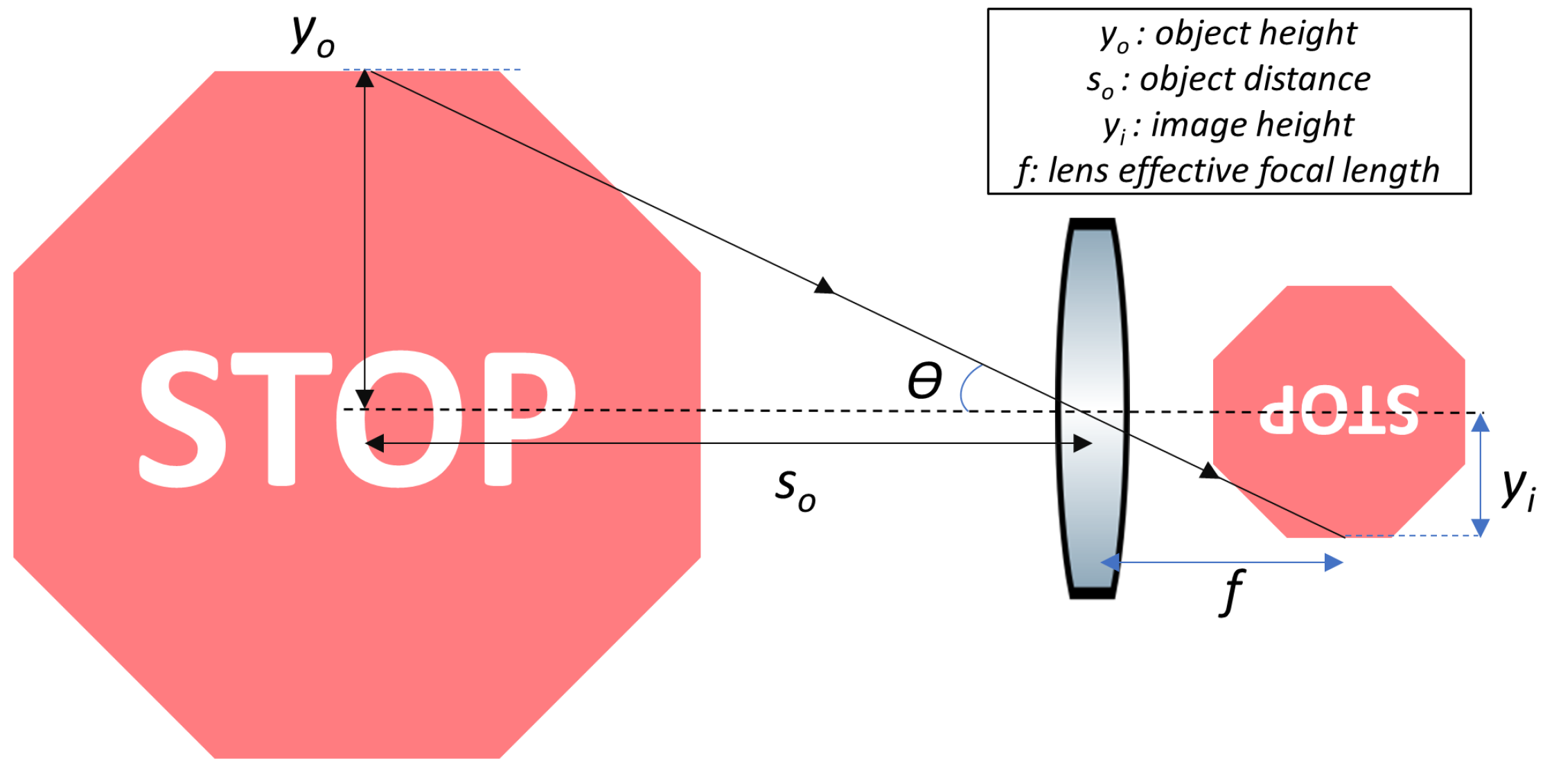
The camera design presented in this paper sets the goal of traffic sign recognition at 200 m. If the image of a traffic sign is to occupy 32 × 32 pixels on the image plane, the physical size of this image patch should be 72 m × 72 m for the Sony IMX324 sensor or 67 m × 67 m for the other two aforementioned automotive image sensors. To be compatible with all three sensors, the pixel size of m and the array size of the Sony sensor are selected as the reference design parameters. If an object distance of 200 m is assumed, for a traffic sign with 0.75 m × 0.75 m dimensions, the effective focal length of the lens should be 19.2 mm, as calculated using the trigonometric relationship shown in Figure 1. This results in a diagonal field of view of about 26.5° with the Samsung S5K2G1 image sensor or 28.3° with the Sony IMX324 image sensor.
With 19.2 mm effective focal length and a pixel size of m, the hyperfocal distance for an f/2 lens is 82 m and 102 m for an f/1.6 lens. When focused at the hyperfocal distance, these lenses can provide sharp images from 41 m to infinity (f/2 lens) or from 51 m to infinity (f/1.6 lens). Thus, these fixed-focus lenses provide long-range imaging.
4. Athermal Lens Design
When temperature changes, several parameters that determine the optical properties of a multi-element lens also change. Most significant are the change of refractive index of lens materials, expansion or contraction of a lens element’s physical dimensions and change in the distances between lens elements. These effects are due to dependence of refractive index on temperature (known as ), and coefficient of thermal expansion (CTE) of lens and spacer materials. Thermal effects on lenses are more pronounced in the infrared region, as of infrared materials are typically orders of magnitude larger than those of visible glasses [23].
As a representative example, a single positive lens made of Schott N-BK7 glass can be considered [24]. The CTE for N-BK7 is 7 ppm/°C and is 3 ppm/°C. As temperature increases, lens radii scale up and the glass refractive index increases. As the lens radii increase, optical power of the lens reduces, increasing the focal length. With an increase in the refractive index, lens optical power increases, reducing the focal length. The net effect is an increase in the lens focal length (a reduction in optical power) at a rate of about 4 ppm/°C [25].
With a multi-element lens, there are spacers that define the distances between lens elements. Due to the CTE of the spacer materials, the spacings between the lens elements can change with temperature variations. This change in distances between elements might result in altering the lens design and the overall optical performance.
4.1. Athermal Glass Map
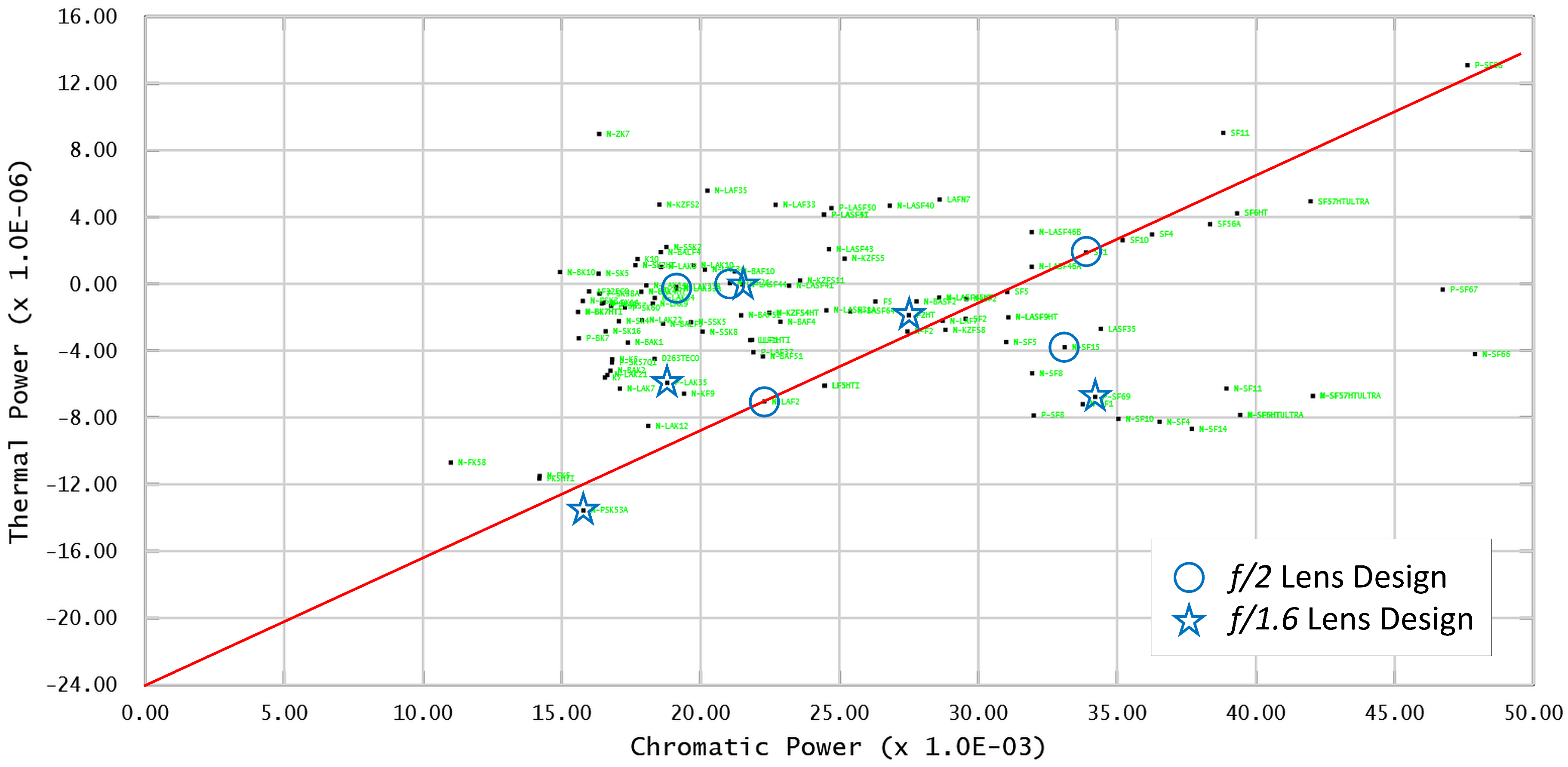
One approach for designing an athermal and also achromatic multi-element lens is through selecting the glasses from an athermal glass map [26,27]. An athermal glass map can be generated by plotting thermal dispersive power (, Equation (1)) of glasses on the y-axis and the chromatic dispersive power (, Equation (2)), which is the inverse of Abbe number V, on the x-axis [27].
In the thermal dispersive power equation, is the derivative of refractive index at the reference wavelength () with respect to the reference temperature, and is the coefficient of thermal expansion for the glass. In the chromatic dispersive power equation, is the refractive index at the short wavelength, and is the refractive index at the long wavelength. In this paper, since the lenses operate over the visible spectrum, , and are 486 nm, 588 nm and 656 nm, respectively (Fraunhofer FdC wavelengths).
An athermal glass map for Schott preferred glasses [24] is shown in Figure 2. Using this plot, a line that has a thermal power axis intercept value set to the negative of the selected barrel material and also passing through two glasses can be drawn. The two glasses on this line satisfy athermal and achromatic conditions for the selected lens barrel material. Optimally, the two glasses should have a large Abbe number difference, i.e., long separation on the chromatic power axis, to achieve lenses with large radii and therefore reduced aberrations. This graphical method is useful for designing an achromatic and athermal doublet housed in a lens barrel, assuming thin lenses in contact [27].
An achromatic lens design is one that brings two wavelengths of light (typically red and blue for lenses operating in the visible spectrum) to the same focus. However, in order to realize a high-resolution imaging system, axial and lateral color should be minimized over the entire spectrum of interest. For a lens design with more than two elements, more than two types of glasses (with different refractive indices and Abbe numbers) can be selected to minimize chromatic aberration over the entire wavelength range.
Modern optical design software packages typically have built-in tools for automatically selecting optimal lens materials during design optimization. Zemax OpticStudio has a glass substitution tool that can perform this material selection during Global Optimization or Hammer Optimization [28]. Similarly, CODE V has a glass selection algorithm called Glass Expert [29]. After constructing an initial lens setup with multi-configuration thermal pickups, global optimization algorithms might be able to deliver a high-resolution, athermal lens design solution.
An optimal lens design solution can be obtained quickly and efficiently if the optimization starting point is close to the final design. Therefore, using the graphical method to select two lens materials that can satisfy some level of thermal invariance and chromatic correction is very beneficial. This provides a good starting point that can be further optimized in optical design software.
4.2. Lens Design Optimization
To meet the resolution and athermal operation requirements for the long-range automotive camera, a 5-element lens with Schott preferred glasses [24] was designed. The camera is to operate over the visible spectrum, therefore Fraunhofer FdC wavelenghts were defined for the lens. Aluminum was assumed as the lens barrel material and has a CTE of about 24 ppm/°C. The general design goals and parameters for the lens are summarized in Table 2.
4.3. Lens Design with Spherical Surfaces
On the athermal glass map, a straight line can be drawn between glasses N-LAF2 and SF1 with a thermal power axis intercept value of , as shown in Figure 2. This means that with aluminum as the lens barrel and spacer material, N-LAF2 and SF1 can be used to design an athermal and achromatic lens. After determining the two glass materials that satisfy the athermal and achromatic properties, a global search in the solution space was performed with SYNOPSYS [30] optical design software’s internal DSEARCH global optimization algorithm using only these two glasses. For this global search, the system temperature was set at 20 °C. Once an initial solution was found, the design was transferred to Zemax OpticStudio [28] for further optimization. In Zemax, a multi-configuration system with the default configuration (20 °C) and additional thermal pickups for °C and 80 °C was generated. With a multi-configuration lens, different configurations are co-optimized to minimize the merit function value for each configuration. The multi-configuration lens was optimized with Hammer Optimization in Zemax with glass substitution enabled. In this mode, as part of the optimization the optimizer is permitted to substitute the lens glasses from a pre-determined glass list.
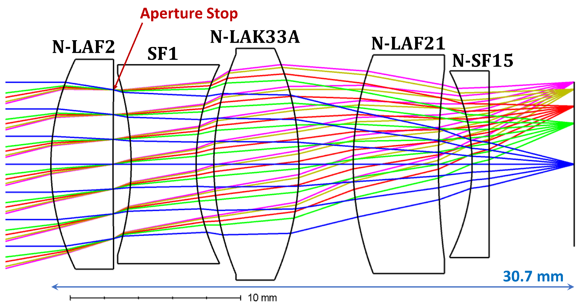
Even though the two initial glasses satisfy achromatic condition, in order to achieve high-resolution imaging over the full visible spectrum, different glasses can be used to minimize secondary color. As shown in Figure 3, the last three lens elements were optimally selected to have different glasses than the initial design during Hammer Optimization. These three glasses (N-LAK33A, N-LAF21 and N-SF15) have anomalous partial dispersion, and therefore help with secondary color correction.
The final, optimized lens design is shown in Figure 3. The lens is f/2, and all surfaces are spherical. The aperture stop is placed on the back surface of the first lens. The distance from the first surface vertex to the image plane (i.e., total track length, TTL, in Zemax) is 30.7 mm, and the lens has less than 1% optical distortion.
The optical performance is evaluated on-axis, and at 0.5, 0.7, 0.9 field locations at the image plane. Modulation transfer function (MTF) plot for the lens at the nominal temperature (20 °C) is shown in Figure 4. On-axis, MTF is 0.68 at 111 lp/mm (Nyquist/2 frequency for the Sony IMX324 sensor) and 0.44 at 222 lp/mm (Nyquist frequency for the Sony IMX324 sensor). At the corner (0.9-field), minimum MTF is 0.54 at 111 lp/mm, and 0.29 at 222 lp/mm.
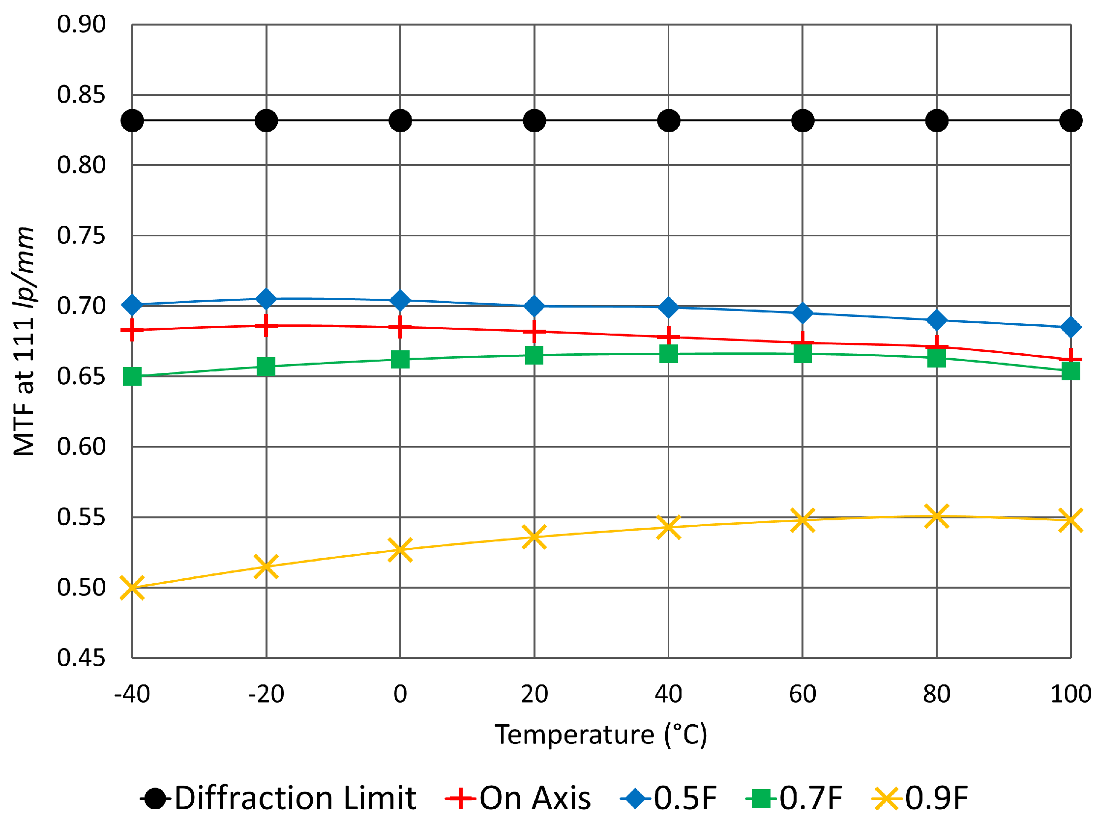
To demonstrate athermal performance, minimum MTF at 111 lp/mm is plotted at different field locations for the temperature range of °C to 100 °C, as shown in Figure 5. Temperature variation is very small for field angles up to 0.7-field, however corner performance (0.9-field) starts degrading at low temperatures. Nonetheless, MTF is greater than 0.65 up to 0.7-field and greater than 0.5 up to the 0.9-field over the entire temperature range. This means sharp, high-resolution images can be formed with the designed lens with minimal temperature influence.
4.4. Lens Design with Two Aspherical Surfaces
After designing the initial lens with only spherical surfaces, the lens was further optimized to increase light throughput, that is the f/# was reduced from f/2 to f/1.6. To deliver high-resolution at the reduced f/#, two lens surfaces were sequentially converted to aspheres as the optimization progressed. Once again, the lens was a multi-temperature, multi-configuration system and glass materials were also allowed to vary during Hammer Optimization in Zemax.
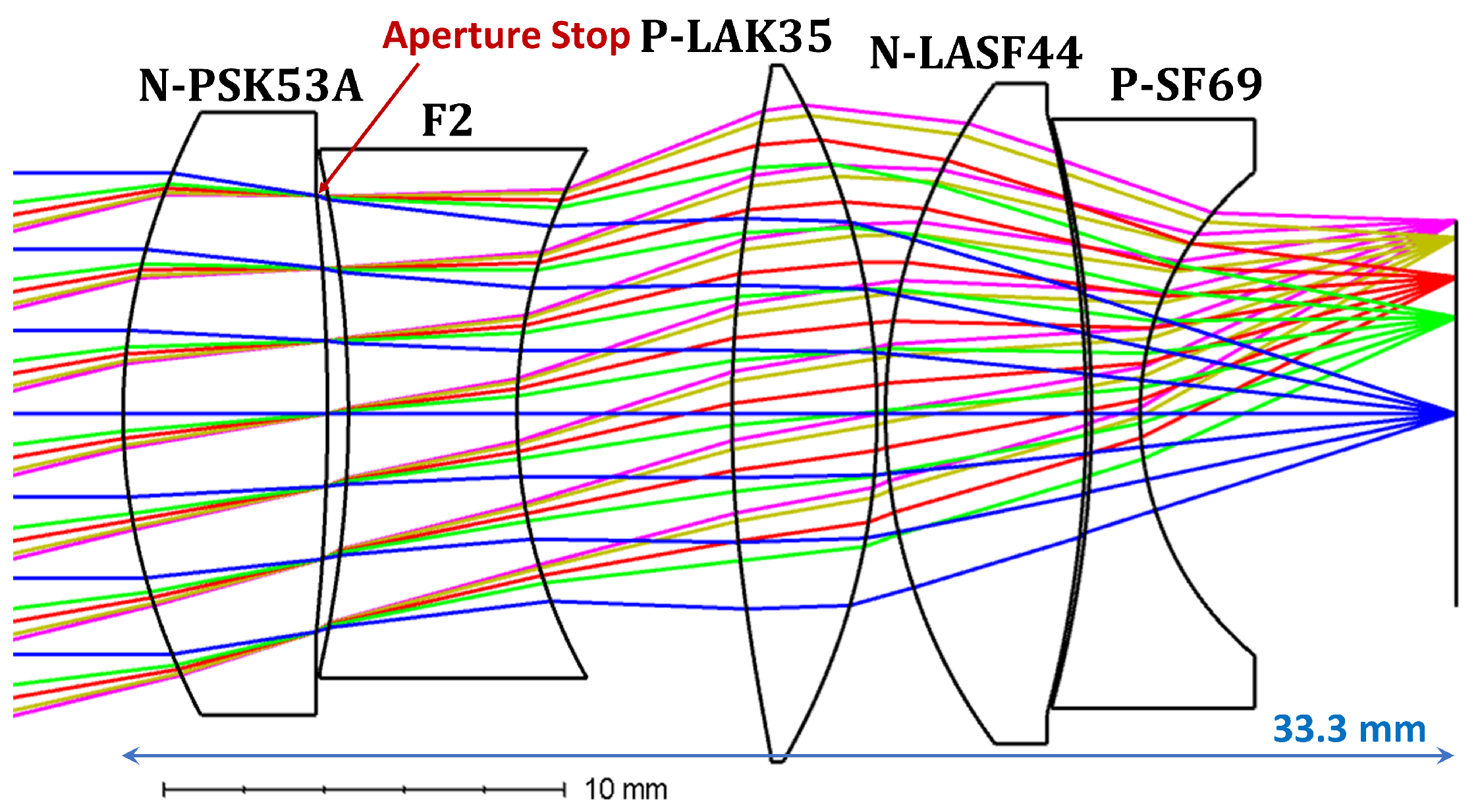
The final, optimized f/1.6 lens design is shown in Figure 6. The front surface of the first lens and the front surface of the third lens are aspherical surfaces, and the aperture stop is again on the back surface of the first lens. The distance from the first surface vertex to the image plane is 33.3 mm, and the lens has less than 1% optical distortion.
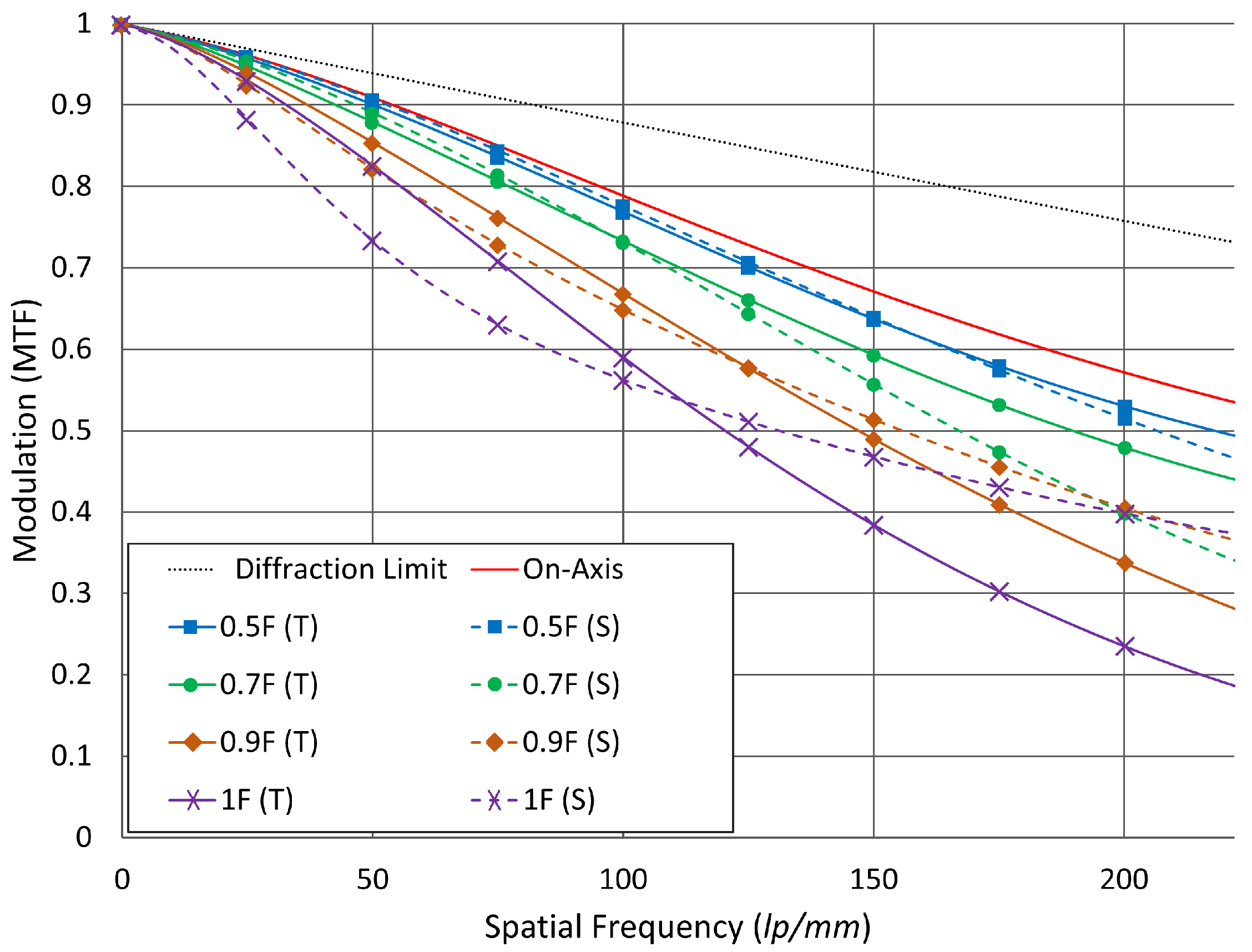
The optical performance is evaluated at on-axis, 0.5, 0.7 and 0.9 field locations at the image plane. MTF plot for the lens at the nominal temperature (20 °C) is shown in Figure 7. On-axis, MTF is 0.76 at 111 lp/mm and 0.53 at 222 lp/mm. At the corner (0.9-field), minimum MTF is 0.62 at 111 lp/mm, and 0.28 at 222 lp/mm.
To demonstrate athermal performance, minimum MTF at 111 lp/mm is plotted at different field locations for the temperature range of °C to 100 °C, as shown in Figure 8. Temperature variation is very small for all field angles up to 0.9-field. MTF is greater than 0.6 over the entire temperature range up to the 0.9-field. Introducing the two aspherical surfaces allowed for achieving better MTF at the mid frequencies and also better athermalization together with increased light throughput.
5. Discussion
Accurate object detection and recognition with computer vision algorithms depend on many factors, such as the optical and digital resolution of the image patch, illumination level of the environment and the object, and image noise. For traffic sign recognition, recognition distance might change depending on the algorithm. Considering the lens designs presented in this paper, if one algorithm can recognize traffic signs from 64 × 64-pixel (digital resolution) image patches, the range would be about 100 m. With an algorithm that can recognize traffic signs from 16 × 16-pixel image patches, the detection range would be about 400 m. The sharpness of the digital images also effects the recognition success rate. Even though the presented lenses provide high MTF up to the chosen spatial sampling frequency, the success rate needs to evaluated for any given computer vision algorithm. Simulated images can be utilized for initial evaluation, and once the lenses are built, as-built lenses can be tested in real-life conditions.
The two lenses presented in this paper are optimized to have minimal performance degradation from °C to 100 °C, with nominal operation at 20 °C. For the design optimization, the default glass parameters for CTE and were used, as provided in Zemax. The refractive index, Abbe number and thermal dispersive power values for the glass materials used in the lens designs are listed in Table 3. The temperature coefficients for refractive index (supplied by Schott), can be used to calculate the refractive index in the temperature range from °C to 140 °C [31]. However, the CTE parameter is quoted for a range of temperatures. Schott typically supplies two different CTE values for the ranges °C to 70 °C and 20 °C to 300 °C. The glass catalog in Zemax has the CTE value corresponding to the °C to 70 °C range.
It is important to note that the athermal behavior of the as-implemented, compound lenses will be heavily influenced by the accuracy of the supplied CTE values for the glasses of which the lens elements are made. It may be that these CTE values may not be accurate beyond the °C to 70 °C range. To achieve mass production and wide adoption of these multi-element lenses, it is necessary for pre-production prototypes to be tested at the extremes of the specified temperature ranges to verify athermal behavior.
With high tolerance lens element manufacturing and accurate assembly, as-built optical systems typically provide excellent agreement with the modeling results implemented in optical design software. Nonetheless, as the next step, the presented lenses will be produced, characterized and tested in a wide range of operating conditions.
6. Conclusions
Computer vision-based driver assistance and autonomous driving systems are invaluable for a range of applications including recognition of road conditions and early warning. Automotive cameras are typically fixed-focus, and forward-facing automotive cameras generally need relatively long focal lengths to provide information about distant objects. The optical system for these cameras should provide high-resolution, and also operate over a wide range of environmental conditions. Accordingly, development of passively athermalized lenses is crucial.
In this paper, two passively athermalized, visible spectrum lens designs for next-generation, long-range automotive cameras are presented. The camera design parameters are derived from the functional requirement of traffic sign recognition at 200 m distance. The lenses are designed from scratch using a multitude of design tools and software; including a graphical glass selection method for athermal and achromatic lens design, a fast global optimization algorithm (DSEARCH algorithm in SYNOPSYS) for an optimized design with two different glass types and finally global and local optimization (with Hammer and Local Optimization algorithms in Zemax OpticStudio) to arrive at high-resolution, athermal lens designs. Both lenses are athermalized from °C to 100 °C.
The first lens design has five glass elements with only spherical surfaces. The lens is f/2 and has an MTF of greater than 0.5 at 111 lp/mm over the entire temperature range. The second lens design has five glass elements and two of the lens surfaces are aspheres. The lens is f/1.6 and has an MTF of greater than 0.6 at 111 lp/mm over the temperature range.
With an f/# value of f/1.6, using preferred glasses from Schott, and obtaining high MTF contrast over the entire image with minimal performance degradation from °C to 100 °C, the lens design shown in Figure 6 meets requirements of both assisted and fully autonomous driving. It can be integrated with an 8-MP image sensor array to form a long-range, high-resolution automotive camera that can be mass-produced and widely employed in modern vehicles, and achieve resolution of current automotive cameras.
Funding
This research received no external funding.
Conflicts of Interest
The author declares no conflict of interest.
References
- Taş, Ö.Ş.; Kuhnt, F.; Zöllner, J.M.; Stiller, C. Functional system architectures towards fully automated driving. In Proceedings of the 2016 IEEE Intelligent Vehicles Symposium (IV), Gotenburg, Sweden, 19–22 June 2016; pp. 304–309. [Google Scholar]
- Rudolph, G.; Voelzke, U. Three Sensor Types Drive Autonomous Vehicles. Available online: https://www.sensorsmag.com/components/three-sensor-types-drive-autonomous-vehicles (accessed on 24 April 2018).
- Bronzi, D.; Zou, Y.; Villa, F.; Tisa, S.; Tosi, A.; Zappa, F. Automotive three-dimensional vision through a single-photon counting SPAD camera. IEEE Trans. Intell. Transp. Syst. 2016, 17, 782–795. [Google Scholar] [CrossRef]
- Ors, A. RADAR, Camera, LiDAR and V2X for Autonomous Cars. Available online: https://blog.nxp.com/automotive/radar-camera-and-lidar-for-autonomous-cars (accessed on 24 April 2018).
- Sahin, F.E.; Tanguay, A.R. Distortion optimization for wide-angle computational cameras. Opt. Express 2018, 26, 5478–5487. [Google Scholar] [CrossRef] [PubMed]
- Hamada, K.; Hu, Z.; Fan, M.; Chen, H. Surround view based parking lot detection and tracking. In Proceedings of the 2015 IEEE Intelligent Vehicles Symposium (IV), Seoul, Korea, 28 June–1 July 2015; pp. 1106–1111. [Google Scholar]
- Sahin, F.E. Fisheye lens design for sun tracking cameras and photovoltaic energy systems. J. Photonics Energy 2018, 8, 035501. [Google Scholar] [CrossRef]
- Dagan, E.; Mano, O.; Stein, G.P.; Shashua, A. Forward collision warning with a single camera. In Proceedings of the 2004 IEEE Intelligent Vehicles Symposium, Parma, Italy, 14–17 June 2004; pp. 37–42. [Google Scholar]
- Bajracharya, M.; Moghaddam, B.; Howard, A.; Brennan, S.; Matthies, L.H. A fast stereo-based system for detecting and tracking pedestrians from a moving vehicle. Int. J. Robot. Res. 2009, 28, 1466–1485. [Google Scholar] [CrossRef]
- Mody, M. ADAS Front Camera: Demystifying Resolution and Frame-Rate. Available online: https://www.eetimes.com/author.asp?section_id=36&doc_id=1329109# (accessed on 24 April 2018).
- Belcarz, K.; Białek, T.; Komorkiewicz, M.; Żołnierczyk, P. Developing autonomous vehicle research platform—A case study. In IOP Conference Series: Materials Science and Engineering; IOP Publishing: Bristol, UK, 2018; Volume 421, p. 022002. [Google Scholar]
- OnSemi AR0820AT Image Sensor Product Overview. Available online: http://www.onsemi.com/PowerSolutions/product.do?id=AR0820AT (accessed on 24 April 2018).
- Samsung S5K2G1 Automotive Image Sensor Webpage. Available online: http://www.samsung.com/semiconductor/image-sensor/automotive-image-sensor/S5K2G1/ (accessed on 24 April 2018).
- Sony Releases the Industry’s Highest Resolution 7.42 Effective Megapixel Stacked CMOS Image Sensor for Automotive Cameras. 2017. Available online: https://www.sony.net/SonyInfo/News/Press/201710/17-094E/index.html (accessed on 24 April 2018).
- Sahin, F.E. Lens design for active alignment of mobile phone cameras. Opt. Eng. 2017, 56. [Google Scholar] [CrossRef]
- Wittpahl, C.; Zakour, H.B.; Lehmann, M.; Braun, A. Realistic image degradation with measured PSF. Electron. Imaging 2018, 2018. [Google Scholar] [CrossRef]
- IEEE PROJECT 2020—Standard for Automotive System Image Quality. Available online: https://standards.ieee.org/develop/project/2020.html (accessed on 24 April 2018).
- Lauxtermann, S.; Lee, A.; Stevens, J.; Joshi, A. Comparison of global shutter pixels for CMOS image sensors. In Proceedings of the 2007 International Image Sensor Workshop, Ogunquit, ME, USA, 7–10 June 2007; p. 8. [Google Scholar]
- MAX9291/MAX9293 3.12Gbps GMSL Serializers for Coax or STP Output and HDMI Input. Available online: https://datasheets.maximintegrated.com/en/ds/MAX9291-MAX9293.pdf (accessed on 24 April 2018).
- Lehtonen, S. Diagnostics on Gigabit Speed SerDes Video Links. Master’s Thesis, Chalmers University of Technology, Gothenburg, Sweden, 2017. [Google Scholar]
- Torresen, J.; Bakke, J.W.; Sekanina, L. Efficient recognition of speed limit signs. In Proceedings of the 7th International IEEE Conference on Intelligent Transportation Systems, Washington, DC, USA, 3–6 October 2004; pp. 652–656. [Google Scholar]
- Sermanet, P.; LeCun, Y. Traffic sign recognition with multi-scale convolutional networks. In Proceedings of the 2011 International Joint Conference on Neural Networks (IJCNN), San Jose, CA, USA, 31 July–5 August 2011; pp. 2809–2813. [Google Scholar]
- An Introduction to Passive Athermalization. Available online: https://www.edmundoptics.com/resources/application-notes/optics/an-introduction-to-passive-athermalization/ (accessed on 19 January 2019).
- Schott Corp. Schott Optical Glass Collection Datasheets; Schott Corp.: Elmsford, NY, USA, 2017. [Google Scholar]
- Rogers, J. Engineering Design Study: A Lens Athermalized over a Wide Range of Temperatures. In Proceedings of the CODE V User Group Meeting, Pasadena, CA, USA, 3 October 2013. [Google Scholar]
- Tamagawa, Y.; Tajime, T. Expansion of an athermal chart into a multilens system with thick lenses spaced apart. Opt. Eng. 1996, 35, 3001–3007. [Google Scholar] [CrossRef]
- Schwertz, K.; Dillon, D.; Sparrold, S. Graphically selecting optical components and housing material for color correction and passive athermalization. In Proceedings of the Current Developments in Lens Design and Optical Engineering XIII, San Diego, CA, USA, 13–15 August 2012; Volume 8486, p. 84860E. [Google Scholar]
- Zemax LLC. OpticStudio User Manual; Zemax LLC.: Kirkland, WA, USA, 2017. [Google Scholar]
- Synopsys Inc. CODE V Reference Manual; Synopsys Inc.: Mountain View, CA, USA, 2015. [Google Scholar]
- Dilworth, D. The SYNOPSYS Lens Design Program; Optical Systems Design Inc.: East Boothbay, ME, USA, 2009. [Google Scholar]
- Schott Corp. TIE-19: Temperature Coefficient of the Refractive Index; Schott Corp.: Elmsford, NY, USA, 2016. [Google Scholar]
Figure 1.
Simplified imaging geometry of a stop sign. (Not drawn to scale.)

Figure 2.
Athermal glass map for Schott preferred glasses [24]. Lens glasses used in the two designs presented in this paper are highlighted. The straight line has a thermal power axis intercept value of , which is the negative of aluminum’s CTE. Zemax has a built-in function called “Athermal Glass Map” that can generate similar plots [28].

Figure 3.
Schematic drawing of the multi-element lens design. The lens is f/2 and with only spherical surfaces.
Figure 3.
Schematic drawing of the multi-element lens design. The lens is f/2 and with only spherical surfaces.

Figure 4.
Modulation transfer function (MTF) plot for the designed f/2 lens (as shown in Figure 3) at nominal temperature of 20 °C. Tangential (T) components are shown with solid lines, sagittal (S) components are shown with dashed lines.
Figure 4.
Modulation transfer function (MTF) plot for the designed f/2 lens (as shown in Figure 3) at nominal temperature of 20 °C. Tangential (T) components are shown with solid lines, sagittal (S) components are shown with dashed lines.

Figure 5.
Minimum MTF at 111 lp/mm for the designed f/2 lens (as shown in Figure 3) at different temperatures. For off-axis fields, smaller of the tangential or sagittal MTF value at each temperature is plotted.
Figure 5.
Minimum MTF at 111 lp/mm for the designed f/2 lens (as shown in Figure 3) at different temperatures. For off-axis fields, smaller of the tangential or sagittal MTF value at each temperature is plotted.

Figure 6.
Schematic drawing of the multi-element lens design. The lens is f/1.6 and with two aspherical surfaces (L1S1 and L3S1).
Figure 6.
Schematic drawing of the multi-element lens design. The lens is f/1.6 and with two aspherical surfaces (L1S1 and L3S1).

Figure 7.
Modulation transfer function (MTF) plot for the designed f/1.6 lens (as shown in Figure 6) at nominal temperature of 20 °C. Tangential (T) components are shown with solid lines, sagittal (S) components are shown with dashed lines.
Figure 7.
Modulation transfer function (MTF) plot for the designed f/1.6 lens (as shown in Figure 6) at nominal temperature of 20 °C. Tangential (T) components are shown with solid lines, sagittal (S) components are shown with dashed lines.

Figure 8.
Minimum MTF at 111 lp/mm for the designed f/1.6 lens (as shown in Figure 6) at different temperatures. For off-axis fields, smaller of the tangential or sagittal MTF value at each temperature is plotted.
Figure 8.
Minimum MTF at 111 lp/mm for the designed f/1.6 lens (as shown in Figure 6) at different temperatures. For off-axis fields, smaller of the tangential or sagittal MTF value at each temperature is plotted.


Table 1.
Key parameters of commercially available, high-resolution automotive image sensors.
| Image Sensor | OnSemi AR0820AT [12] | Sony IMX324 [14] | Samsung S5K2G1 [13] |
|---|---|---|---|
| Resolution | |||
| Pixel Size (m) | 2.1 | 2.25 | 2.1 |
| Nyquist Frequency (lp/mm) | 238 | 222 | 238 |
| Pixel Array Size (mm) | |||
| Array Diagonal Size (mm) | 9.28 | 9.69 | 9.02 |
Table 2.
Specifications of the long-range automotive camera lens.
| Parameter | Specification |
|---|---|
| Elements | 5 glass elements |
| Image Size | 9.687 mm |
| Field of View | ±14.2° (diagonal) |
| Wavelength Range | Visible |
| Distortion | <1% optical distortion |
| Image Clearance | >5 mm |
| Lens Barrel | Aluminum (CTE = 24 ppm/°C) |
| Temperature Range | °C to 100 °C |
Table 3.
Refractive index (n), Abbe number (V) and thermal dispersive power () values for the glass materials used in the lens designs presented in this paper [24].
Table 3.
Refractive index (n), Abbe number (V) and thermal dispersive power () values for the glass materials used in the lens designs presented in this paper [24].
| Glass | Refractive Index | Abbe Number | Thermal Dispersive Power (10) |
|---|---|---|---|
| N-LAF2 | 1.744 | 44.85 | −7.04 |
| SF1 | 1.717 | 29.51 | 1.87 |
| N-LAK33A | 1.754 | 52.27 | −0.3 |
| N-LAF21 | 1.788 | 47.49 | 0.04 |
| N-SF15 | 1.699 | 30.20 | −3.8 |
| N-PSK53A | 1.618 | 63.39 | −13.57 |
| F2 | 1.620 | 36.37 | −1.88 |
| P-LAK35 | 1.694 | 53.20 | −5.93 |
| N-LASF44 | 1.804 | 46.50 | −0.03 |
| P-SF69 | 1.723 | 29.23 | −6.77 |
© 2019 by the author. Licensee MDPI, Basel, Switzerland. This article is an open access article distributed under the terms and conditions of the Creative Commons Attribution (CC BY) license (http://creativecommons.org/licenses/by/4.0/).
Share and Cite
MDPI and ACS Style
Sahin, F.E. Long-Range, High-Resolution Camera Optical Design for Assisted and Autonomous Driving. Photonics 2019, 6, 73. https://doi.org/10.3390/photonics6020073
AMA Style
Sahin FE. Long-Range, High-Resolution Camera Optical Design for Assisted and Autonomous Driving. Photonics. 2019; 6(2):73. https://doi.org/10.3390/photonics6020073
Chicago/Turabian StyleSahin, Furkan E. 2019. "Long-Range, High-Resolution Camera Optical Design for Assisted and Autonomous Driving" Photonics 6, no. 2: 73. https://doi.org/10.3390/photonics6020073
Note that from the first issue of 2016, this journal uses article numbers instead of page numbers. See further details here.