Communication

Hybrid Resonator 1319 nm Nd:YAG InnoSlab Laser

1
National Institute of Metrology of China, Beijing 100029, China
2
School of Optoelectronics, Beijing Institute of Technology, Beijing 100081, China
*
Author to whom correspondence should be addressed.
These authors contributed equally to this work.
Photonics 2023, 10(6), 652; https://doi.org/10.3390/photonics10060652
Submission received: 17 April 2023 / Revised: 22 May 2023 / Accepted: 26 May 2023 / Published: 5 June 2023

Abstract

:
The InnoSlab laser has the advantages of excellent thermal management and high overlapping efficiency. In this work, we report an InnoSlab laser with high efficiency at 1319 nm end-pumped 0.6at.% Nd:YAG by 808 nm. The hybrid stable–unstable resonator was adopted. For a cavity length of 17.9 mm and absorbed pumped power of 423.5 W, the output power of 81 W was obtained at T = 5%, exhibiting an optical conversion efficiency of 19.13% and a slope efficiency of 29.80%.

1. Introduction

High-power diode pump solid-state lasers operating at 1319 nm have plenty of applications in the fields of sodium beacons, optical communication, and laser medical treatment, owing to the minimum dispersion for silica optical fiber and good absorption of water molecules [1,2]. Generally, the Nd:YAG laser pumped by 808 nm laser diode (LD) is an efficient alternative to achieving 1319 nm laser output due to the transitions between stark sub-levels corresponding to 4F3/24I13/2 energy levels of Nd3+ ions [3]. There are various transition ways between energy levels of Nd3+ in Nd:YAG crystal. The 4F3/24I13/2 transition has two overlapped stark transitions irradiating 1319 nm and 1338 nm wavelength, respectively, with approximate effective stimulated emission cross sections and only one-fifth that of the 1064 nm wavelength. Therefore, it is challenging to directly obtain the high-power 1319 nm single-wavelength laser output, attributed to the mode competition effect. In recent years, the exploration of 1319 nm laser output was accelerated by the reasonable design of the laser-cavity mirror coating [1], utilizing the dichroic mirror technology [4,5] or inserting the solid etalon [6,7], suppressing the oscillations of undesired laser lines to realize single wavelength operation.
In the past, most research at 1319 nm was carried out using Nd:YAG crystal rod [8], which would limit the power scaling influenced by the thermal effect of gain media. Such an effect originating from the quantum defect causes the thermal lens effect and thermal depolarization [9]. In order to achieve an efficient output, researchers have tried various methods, such as using an intracavity lens [6] and crystal with a concave end face, decreasing the Stokes shift between the pump and the laser photon energies [7,10], even adopting the double gain host with 90° quartz polarization rotators [6], etc. Moreover, studies about crystal configurations, such as planar waveguides and slabs, provided a new way of improving the 1319 nm output quality [11,12,13]. A quasi-continuous wave Nd:YAG planar waveguide 1319 nm laser amplifier was reported first in 2019, obtaining optical–optical efficiency of 15.4% [4]. Furthermore, an end-pumped 1319 nm Nd:YAG slab amplifier laser with an output power of 51.5 W was obtained [13], which was ascribed to the excellent heat conductivity mechanism of the slab laser.
The LD partially end-pumped slab laser (InnoSlab) with hybrid resonator combines the outstanding thermal management of a slab and the high overlapping efficiency of end-pumping [14,15]. It is effectively used to generate a high-power laser with good beam quality. However, few studies at 1319 nm resonator using Nd:YAG have been reported based on the InnoSlab structure. Zhang’s group obtained 23.2 W of continuous output power using a stable plano-concave resonator in 2022 [16]. Further, higher output of 109.4 W was obtained by Zhang, in which 1 at.% doping Nd:YAG was adopted and beam quality was limited in the horizontal direction of gain media [17]. Moreover, an output pulse energy of 8.24 mJ long-pulse quasi-continuous wave laser at 1319 nm was realized by the InnoSlab amplifier in 2020 [18].
Herein, we report an Nd:YAG InnoSlab laser at 1319 nm using a hybrid stable–unstable resonator. The maximum continuous output power of 81 W at 1319 nm was obtained with an absorbed pump power of 423 W and the transmission T = 5% at a cavity length of 17.9 mm, exhibiting an optical conversion efficiency of 19.13%.

2. Materials and Methods

The experimental schematic of the 1319 nm InnoSlab oscillator is shown in Figure 1. The slab crystal Nd:YAG of the dimension of 24 mm × 12 mm × 1 mm was end-pumped by a commercial pump source with two vertical stacks of six collimated LD bars. The LD stacks can provide 6 W/A peak power at 808 nm. The maximum pump power is about 500 W at the pump current of 80 A. Each LD bar was individually collimated in the fast-axis direction with a micro-lens. Then, the pump output passed through the shaping system, which mainly consisted of two sets of cylindrical lenses, a rectangular waveguide, and a set of spherical lenses. As shown in the schematic in Figure 1, the pump beam was coupled into a waveguide (4 mm in width and 80 mm in length) through the first set of cylindrical lenses. The two large surfaces of the waveguide were adopted to fully homogenize the beam using repeated total reflection. Then, the output from the waveguide was imaged 1:6 on the end face of the crystal in the unstable cavity direction by the second set of cylindrical lenses in company with spherical lenses. In the stable cavity direction, the beam was focused by the last cylindrical lens. Finally, the pump beam was formed into a rectangular pump line (size approx. 0.45 mm × 24 mm) matching the width of the crystal. The beam shaping system possessed a transfer efficiency of 87%.
For 1319 nm laser operation, a hybrid stable–unstable resonator was adopted. The resonator was stable in the plane of small dimension, and the positive-branch off-axis confocal was unstable in the plane of large dimension of the media. The doping level of gain media Nd:YAG was 0.6at.%. A concave mirror, M1, with a radius of 500 mm and a cylindrical mirror, M2, with a radius of −475 mm, were used as cavity mirrors. M1 and M2 were both coated for high transmission at 808 nm and 1064 nm and high reflection at 1319 nm, which increased losses and suppressed oscillations at 1064 nm. Based on the 500 nm/−475 nm lens combination, the transmission of the output coupler was 5%. The length of the cavity was 17.9 mm. As for thermal management, two large surfaces of Nd:YAG were welded tightly with Indium with the water-cooled copper micro-channel heat sink, series connection with LD stacks, and the temperature of the cooling water was kept at 24.5 °C.

3. Results and Discussion
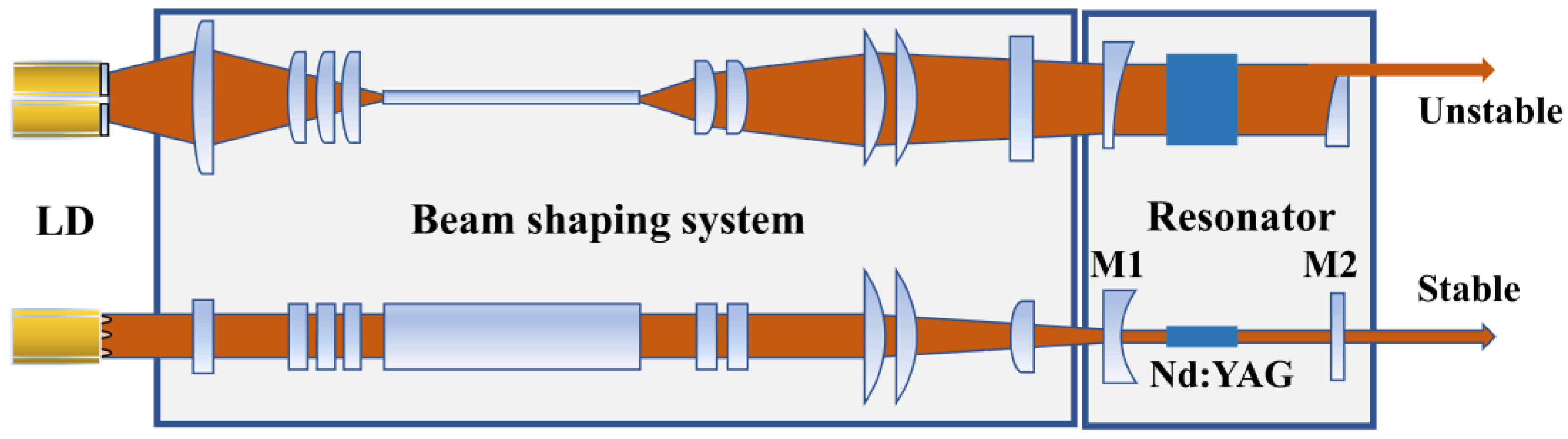
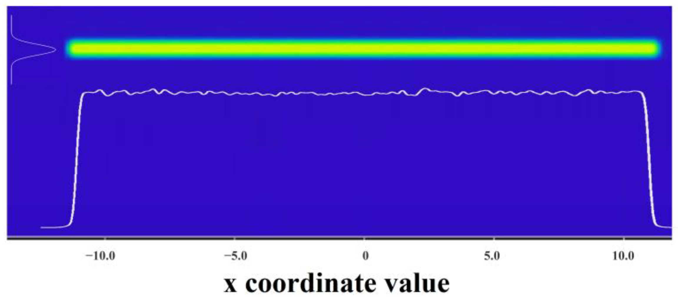
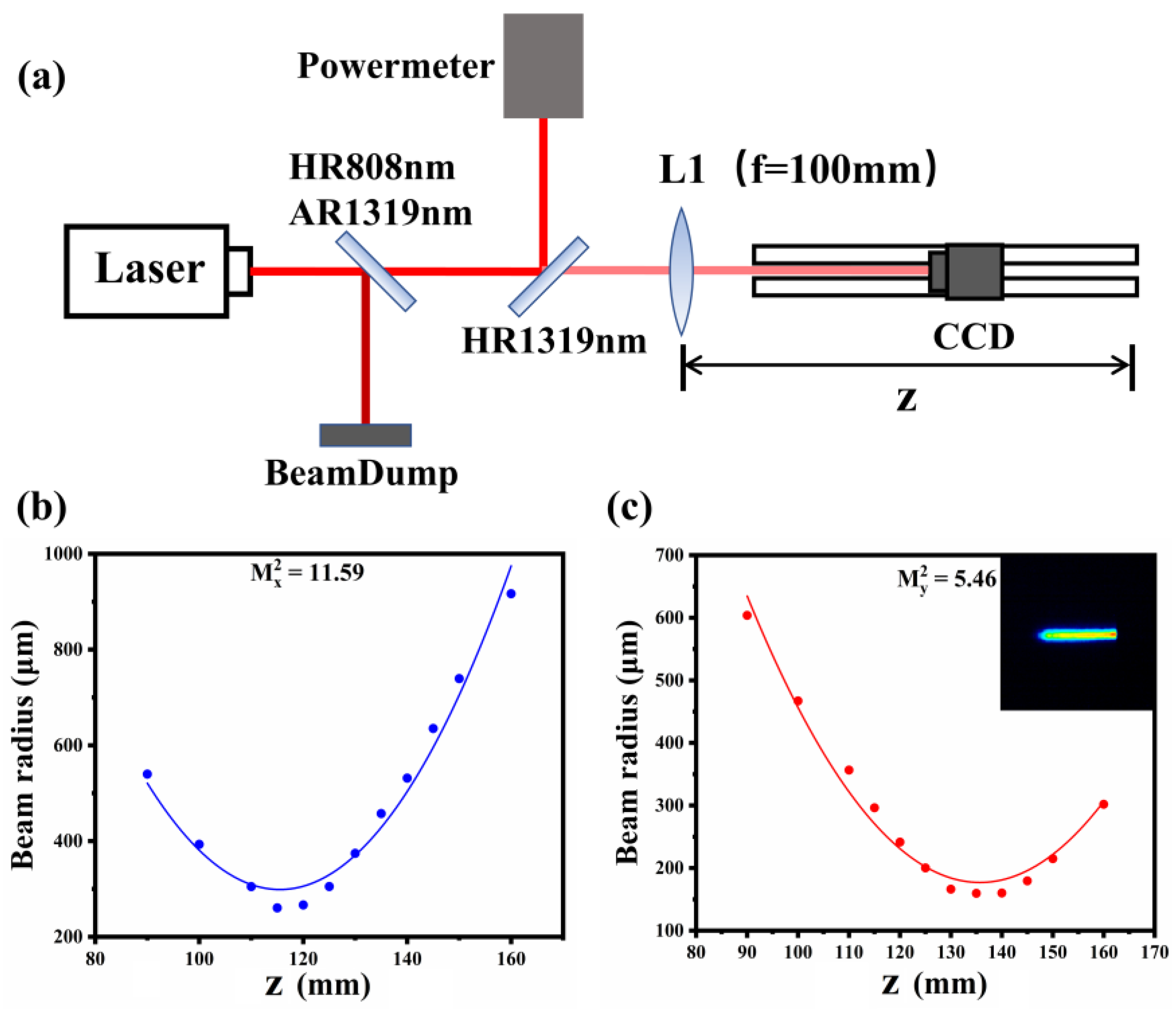
3.1. Shaping System

A pump beam shaping system based on LD was designed and experimentally validated. The pump beam profile and intensity distribution on the end face of the crystal were simulated, as shown in Figure 2. It can be seen that the pump line has a uniform intensity distribution in the horizontal direction with a top-hat of approximately 24 mm in length and a Gaussian distribution with a radius of 227.68 μm in the vertical direction. The output of the beam shaping system was exposed with beam size of ωx ≈ 23,950 μm, ωy ≈ 450 μm, which is pretty close to the simulation results. The shaping coupling efficiency of the shaping system was about 87%.

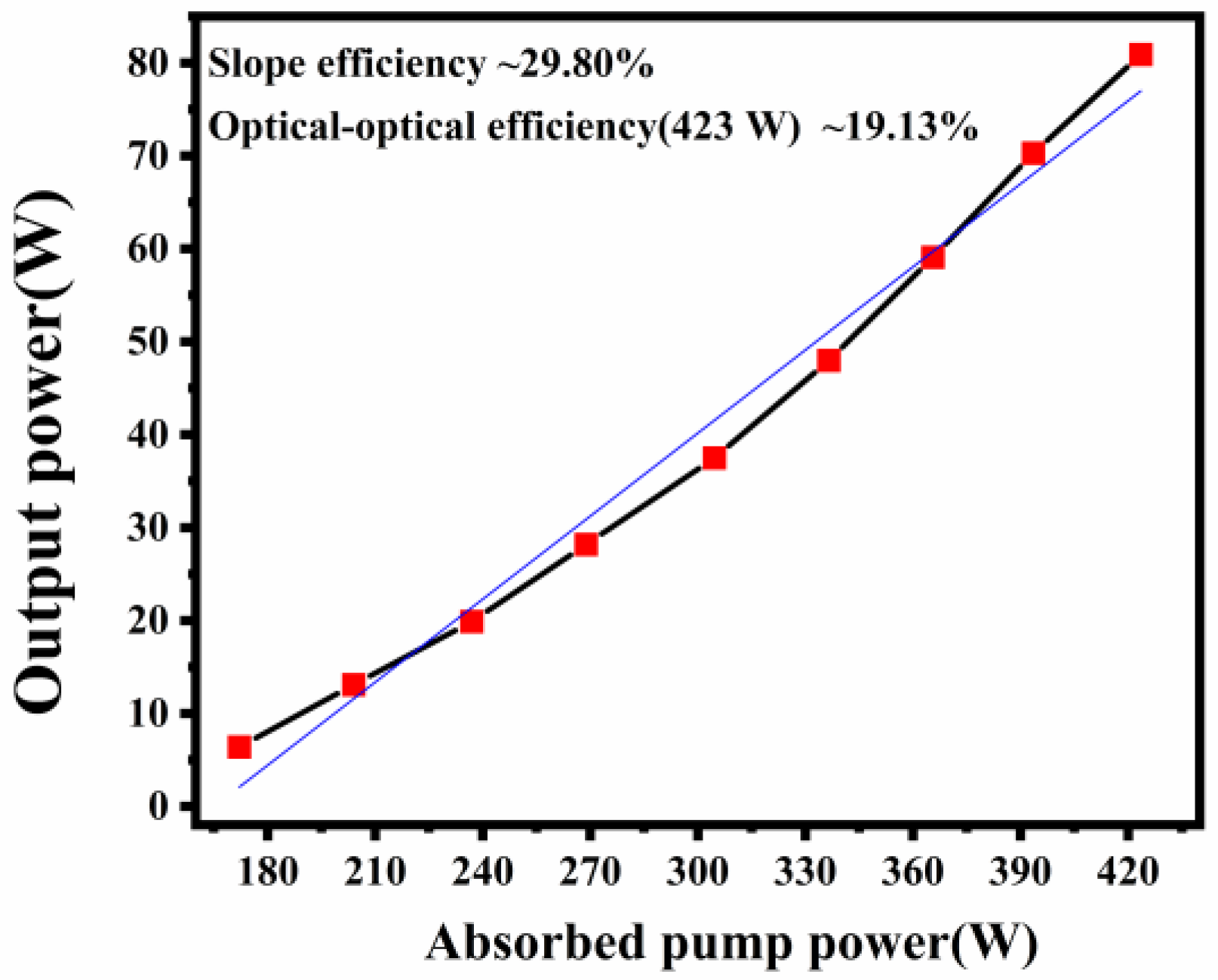
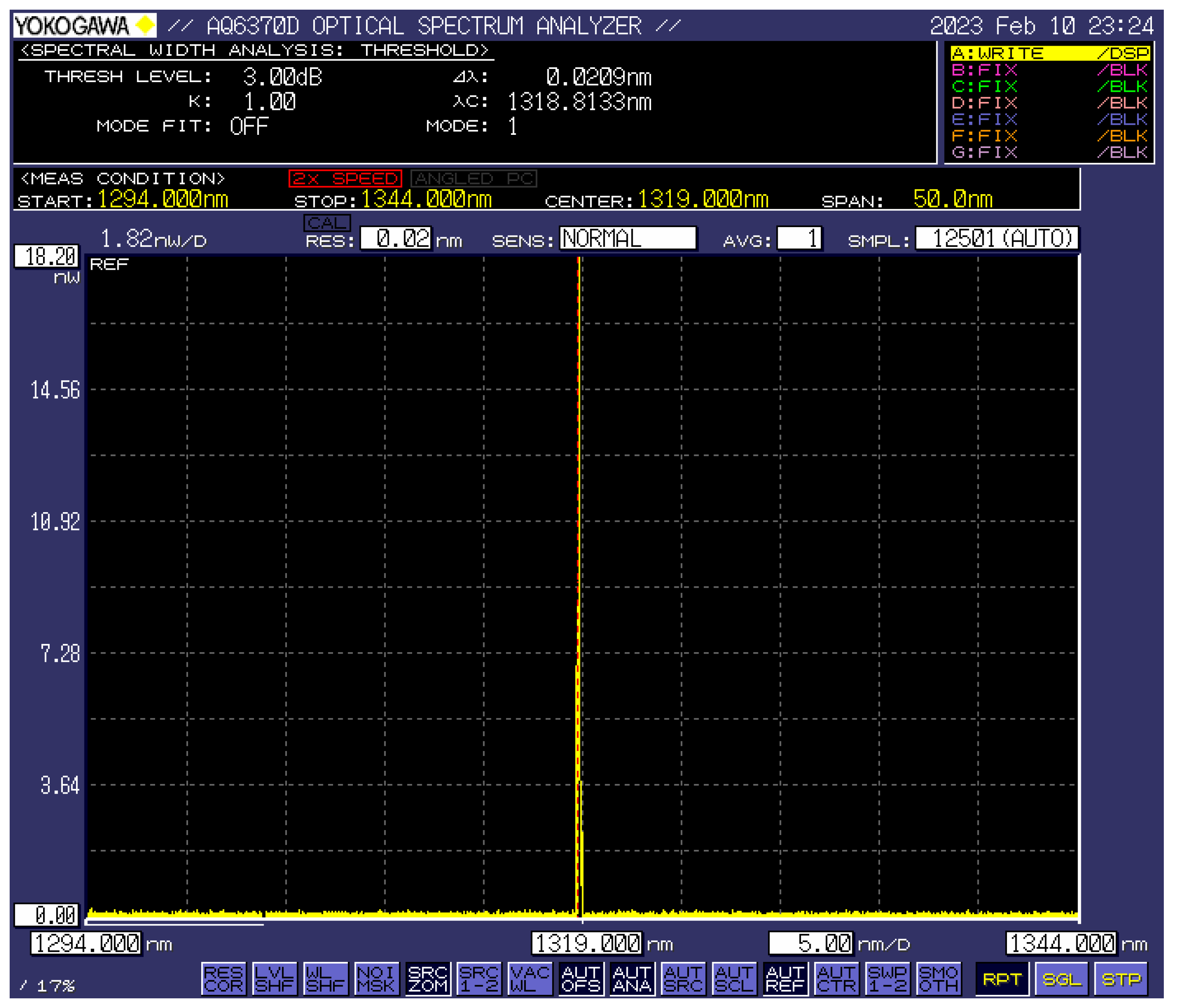
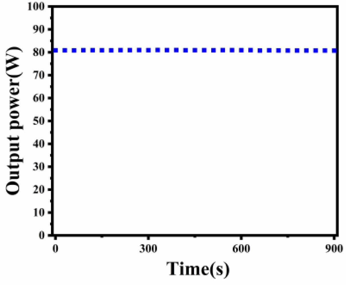
3.2. Characteristics of 1319 nm Nd:YAG InnoSlab Laser

The output power was recorded with an air-cooled power meter. The 1319 nm output power of 81 W was achieved for a cavity length of 17.9 mm and absorbed pumped power of 423.5 W. The system exhibited an optical conversion efficiency of 19.13%. Furthermore, the output was measured in relation to the absorbed pump power, as shown in Figure 3, indicating a slope efficiency of 29.80%. Though saturation of output power was not observed, higher output was limited by pumping power here. The spectrum of the output beam was studied using a spectrum analyzer, demonstrating the laser operation at 1319 nm. It was confirmed that no other lines, including 1338 nm, were output in the range from 1294 nm to 1344 nm, as shown in Figure 4.
We characterized the beam quality factors with a WinCamD CCD and hyperbola fitting method, as shown in the schematic in Figure 5a. A spherical lens, L1, with a focal length of 100 mm, was used to focus the output beam. The results indicated that the output laser possessed the quality of M x 2 = 11.59 and M y 2 = 5.46 in the two orthogonal directions at the output power of 81 W. The inset of Figure 5c is the output beam profile. The generation of higher-order modes in the x-axis was due to the parasitic oscillations originating from the short cavity length, which were not suppressed. Additionally, waist positions on the x-axis located outside the focused position of the lens indicate imperfect collimated output in the x-axis, which provided another access to optimize beam quality. The different waist positions on the X and Y axes were attributed to the focusing lens L1 being out of the Rayleigh length range of the output in the y-axis direction as well as the imperfect collimated output.
In addition, the fluctuation of the output power was measured, and the results are shown in Figure 6. We recorded the output power every 30 s for 15 consecutive minutes at the output of 81 W. The fluctuation of power was less than 0.1%, indicating that the output of the InnoSlab laser was quite stable.

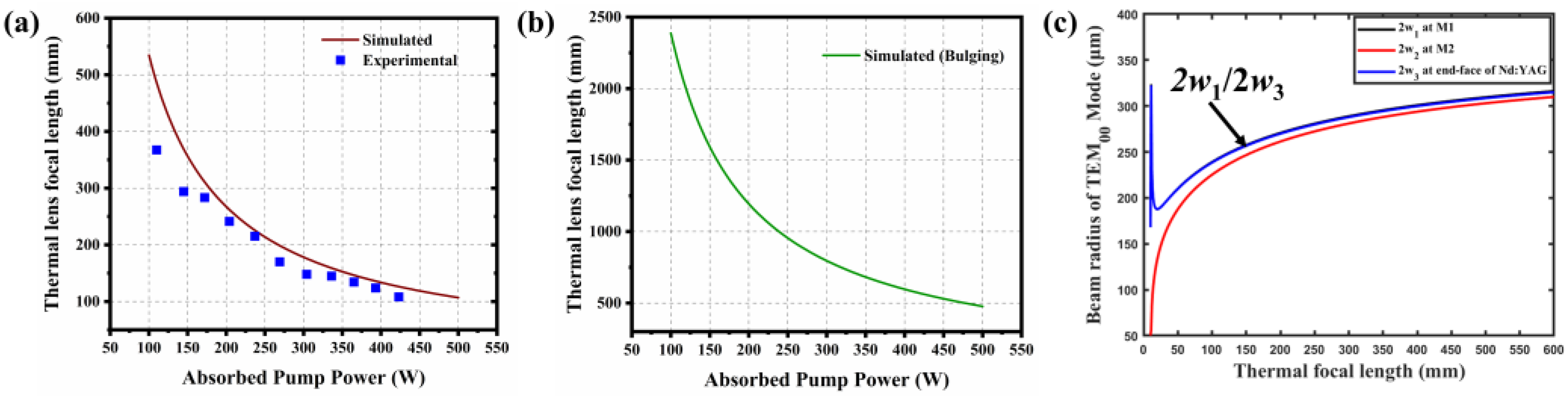
3.3. Theoretical Analysis

In theory, the beam quality and stability were affected by the thermal effects inside the gain media and in a defined resonant cavity. With regard to the InnoSlab laser, the thermal lens effect only occurred in the vertical direction (fast-axis) of the crystal, while an approximately uniform thermal distribution appeared in the horizontal direction due to the uniform intensity distribution of the pump line. According to the ref. [19], the optical thermal lens of the end-pumped slab can be calculated by the combination of the temperature and stress distributions. The thermal lens focal length of slab gain media was determined with different pumped power:
f t 1 = P ( 1 λ p / λ s ) k d w × { d n d T × [ 1 exp ( α L ) ] + 2 α α z d ( n 0 1 ) + ε s }  
where k is the thermal conductivity of the Nd:YAG along the z-axis, d and w indicate the dimensions of the pumped beam in the fast and slow axis, respectively, P is the pumped power, (dn/dT) is the thermal-optic coefficient of YAG, λp and λs are the pump and laser wavelengths, respectively, α is the absorption coefficient at 808 nm, and α z is the thermal expansion coefficient along the z-axis. Here, the focal length of the thermal lens was determined by a combination of the temperature gradient, thermal stress, and thermal deformation of the end face bulge. To simplify the expression, we used ε s to represent the component of the thermal lens introduced by the change in refractive index due to the stress distribution, which was related to the pump polarization direction and always used to employ 3D finite element analysis to achieve an accurate numerical solution. However, according to the results of Koechner’s study [20], for Nd:YAG gain media, the temperature-dependent variation of the refractive index constitutes the major contribution of the thermal lens. The stress-dependent variation of the refractive index modifies the focal length by about 20%. The effect of the bulging of end faces is less than 6%. Therefore, in this work, we only discuss the thermal lens as an expression related to the temperature gradient:
f T = k d w P ( 1 λ p / λ s ) ( d n / d T ) 1 1 exp ( α L )  
We introduced the appropriate materials parameters for Nd:YAG into expression (2). The variation of the thermal lens with absorbed pump power is shown in Figure 7a. The absorbed power corresponded to the product of pump power P and 1 − exp(−αL), and the fractional thermal loading ηh was adopted the theoretical lower limit as ηh = 1 − λps = 0.39. It was observed that the focal length of the thermal lens decreases in the range of 540~120 mm as the pumped power increases within 100~450 W. The thermal length was 126 mm at a maximum output of 81 W.
In addition, the thermal lens caused by the bulging of end faces was simulated according to expression (3) [19].
f 1 = k w P ( 1 λ p / λ s ) α α z ( n 0 1 )  
As shown in Figure 7b, the results indicated that the focal length of the thermal lens induced by the bulging of end faces was distributed in the range of 2500~500 mm, which was negligible compared to the component introduced by the temperature gradient.
Further, we performed experimental measurements on the thermal lens. A collimated probe light was injected into the gain media in the presence of pump light, and then the focal length of the thermal lens was determined by measuring the focused position. The results are plotted in Figure 7a. It was shown that the experimental and simulation results were mostly consistent, indicating the rationality of the approximation of Equation (2). This approximation also resulted in an overall slightly higher simulation curve than the measured results. The significant difference under low pump power was attributed to the fact that the fractional thermal loading ηh under nonlasing conditions was larger than 1 − λp/λs [20].
Figure 7c shows the simulation results for the fundamental mode radius at the cavity mirrors M1, M2, and end of slab crystal as a function of thermal focal length, represented by ω1, ω2, and ω3, respectively. The results demonstrated the significant variation of the radius of TEM00 with thermal focal length under high pumped power. The poor mode matching resulted in a beam quality of 5.46 at the maximal output power. Therefore, optimization of beam quality in the y-axis requires a reasonable design of the cavity parameters to improve the mode-matching of the resonator. Meanwhile, the unstable cavity should ensure collimated output while suppressing the generation of parasitic oscillations.

4. Conclusions

A single-wavelength 1319 nm InnoSlab laser operation pumped by 808 nm was achieved with a hybrid resonator. Through the reasonable design of cavity mirror coating, laser oscillation of other lines was simultaneously suppressed. We obtained as much as 81 W of output power by pumping a slab Nd:YAG doping of 0.6at.%, performing a high optical conversion efficiency of 19.13% and a slope efficiency of 29.80%. The beam quality with M x 2 = 11.59 and M y 2 = 5.46 was obtained. Further increases in beam quality should be possible by increasing the mode-matching of the resonator and suppressing the generation of parasitic oscillations. The laser will be valuable for many applications, such as frequency conversion to red and blue wavelengths, as well as laser therapeutics.

Author Contributions

Conceptualization, S.Z. and X.L.; methodology, S.Z. and T.C.; validation, S.Z. and T.C.; formal analysis, H.Z.; investigation, T.C., S.Z., J.W. and H.G.; writing—original draft preparation, S.Z. and T.C.; writing—review and editing, X.L.; supervision, X.L.; project administration, S.Z.; funding acquisition, X.L. All authors have read and agreed to the published version of the manuscript.

Funding

This research was funded by Ministry of Science and Technology of the People’s Republic of China, grant number 2022YFF0610804.

Institutional Review Board Statement

Not applicable.

Informed Consent Statement

Not applicable.

Data Availability Statement

No new data were created or analyzed in this study. Data sharing is not applicable to this article.

Conflicts of Interest

The authors declare no conflict of interest.

References

  1. Zhu, H.Y.; Zhang, G.; Huang, C.H.; Wei, Y.; Huang, L.X.; Chen, J.; Chen, W.D.; Chen, Z.Q. Diode-side-pumped 131 W, 1319 nm single-wavelength cw Nd:YAG laser. Appl. Opt. 2007, 46, 384–388. [Google Scholar] [CrossRef]
  2. Bian, Q.; Bo, Y.; Zuo, J.W.; Yuan, L.; Gao, H.W.; Peng, Q.J. High-power wavelength-tunable and power-ratio-controllable dual-wavelength operation at 1319 nm and 1338  nm in a Q-switched Nd:YAG laser. Photon. Res. 2022, 10, 2287. [Google Scholar] [CrossRef]
  3. Saha, A.; Ray, A.; Mukhopadhyay, S.; Sinha, N.; Datta, P.K.; Dutta, P.K. Simultaneous multi-wavelength oscillation of Nd laser around 1.3 µm A potential source for coherent terahertz generation. Opt. Express 2006, 14, 4721–4726. [Google Scholar] [CrossRef]
  4. Wang, J.T.; Lin, W.P.; Zhang, L.; Zhou, T.J.; Lu, Y.H.; Gao, Q.S. 1319 nm Nd:YAG Planar Waveguide Laser Amplifier with an optocal to optical Efficiency of 15%. In Proceedings of the Laser Applications Conference, Vienna, Austria, 29 September–3 October 2019. [Google Scholar]
  5. Xiao, Q.; Pan, X.; Guo, J.; Wang, X.; Wang, J.; Jiang, X.; Li, G.; Lu, X.; Wang, X.; Zhou, S.; et al. High-stability, high-beam-quality, and pulse-width-tunable 1319 nm laser system for VISAR applications in high-power laser facilities. Appl. Opt. 2020, 59, 6070–6075. [Google Scholar] [CrossRef] [PubMed]
  6. Inoue, Y.; Fujikawa, S. Diode-Pumped Nd:YAG Laser Producing 122-W CW Power at 1.319 μm. IEEE J. Quantum Elect. 2000, 36, 751–756. [Google Scholar] [CrossRef]
  7. Li, M.L.; Zhao, W.F.; Zhang, S.B.; Guo, L.; Hou, W.; Li, J.M.; Lin, X.C. 1.86 W cw single-frequency 1319 nm ring laser pumped at 885 nm. Appl. Opt. 2012, 51, 1241–1244. [Google Scholar] [CrossRef] [PubMed] [Green Version]
  8. Lu, J.; Lu, J.; Murai, T.; Takaichi, K.; Uematsu, T.; Xu, J.; Ueda, K.-I.; Yagi, H.; Yanagitani, T.; Kaminskii, A.A. 36-W diode-pumped continuous-wave 1319-nm Nd:YAG ceramic laser. Opt. Lett. 2002, 27, 1120–1122. [Google Scholar] [CrossRef] [PubMed]
  9. Park, D.; Jeong, J.; Hwang, S.; Lee, S.; Cho, S.; Yu, T.J. Performance Evaluation of Solid-State Laser Gain Module by Measurement of Thermal Effect and Energy Storage. Photonics 2021, 8, 418. [Google Scholar] [CrossRef]
  10. Lavi, R.; Jackel, S.; Tal, A.; Lebiush, E.; Tzuk, Y.; Goldring, S. 885 nm high-power diodes end-pumped Nd YAG laser. Opt. Commun. 2001, 195, 427–430. [Google Scholar] [CrossRef]
  11. Zheng, J.K.; Bo, Y.; Xie, S.Y.; Zuo, J.W.; Wang, P.Y.; Guo, Y.D.; Liu, B.L.; Peng, Q.J.; Cui, D.F.; Lei, W.Q. High Power Quasi-Continuous-Wave Diode-End-Pumped Nd:YAG Slab Amplifier at 1319 nm. Chin. Phys. Lett. 2013, 30, 074202. [Google Scholar] [CrossRef]
  12. Chen, Z.Z.; Xu, Y.T.; Guo, Y.D.; Wang, B.S.; Xu, J.; Xu, J.L.; Gao, H.W.; Yuan, L.; Yuan, H.T.; Lin, Y.Y. 8.2 kW high beam quality quasi-continuous-wave face-pumped Nd:YAG slab amplifier. Appl. Opt. 2015, 54, 5011–5015. [Google Scholar] [CrossRef]
  13. Guo, C.; Zuo, J.; Bian, Q.; Xu, C.; Zong, Q.; Bo, Y.; Shen, Y.; Zong, N.; Gao, H.; Lin, Y. Compact, high-power, high-beam-quality quasi-CW microsecond five-pass zigzag slab 1319 nm amplifier. Appl. Opt. 2017, 56, 3445–3448. [Google Scholar] [CrossRef]
  14. Du, K.; Liao, Y.; Loosen, P. Nd:YAG slab laser end-pumped by laser-diode stacks and its beam shaping. Opt. Commun. 1997, 140, 53–56. [Google Scholar] [CrossRef]
  15. Du, K.; Clarkson, W.A.; Hodgson, N.; Shori, R.K. Unique performances and favourable applications of INNOSLAB lasers. Proc. SPIE 2009, 7193, 71932B. [Google Scholar] [CrossRef]
  16. Li, X.; Javed, F.; Zhang, H.; Liu, X.; Chen, T.; Yang, S.; Zang, T.; Jiang, Y.; Jiang, J. High power diode end-pumped 1.3 μm Nd:YAG InnoSlab laser. Results Phys. 2022, 37, 105468. [Google Scholar] [CrossRef]
  17. Zang, T.; Yang, S.; Liu, L.; Wang, W.; Meng, S.; Jiang, J.; Zhang, H. LD end-pumped 1319 nm Nd:YAG slab laser. Chin. J. Lasers 2022, 49, 2116001. [Google Scholar]
  18. Zhang, X.; He, T.; Luo, X.; Chen, X.; Zhang, L.; Xu, X.; Ren, H.; Xu, L.; Lu, Y.; Sun, J.; et al. Study of long-pulse quasicontinuous wave INNOSLAB amplifier at 1319 nm. Opt. Eng. 2020, 59, 056112. [Google Scholar] [CrossRef]
  19. Ma, Z.; Li, D.; Gao, J.; Wu, N.; Du, K. Thermal effects of the diode end-pumped Nd:YVO4 slab. Opt. Commun. 2007, 275, 179–185. [Google Scholar] [CrossRef]
  20. Koechner, K. Thermo-Optic Effects, in Solid-State Laser Engineering, 6th ed.; Rhodes, W.T., Ed.; The Springer Series in Optical Sciences: Georgia, GA, USA, 2005; pp. 442–479. [Google Scholar]
Figure 1. The schematic representation of the experimental setup.
Photonics 10 00652 g001
Figure 2. The simulated pump beam profile after shaping system.
Photonics 10 00652 g002
Figure 3. Output power against the absorbed pump power at T = 5%. The blue line represents the linear fitting line.
Photonics 10 00652 g003
Figure 4. The spectrum of output laser.
Photonics 10 00652 g004
Figure 5. M2 measurements of 1319 nm beam under the maximal output power: (a) The schematic of M2 measurements; (b) Results of M2 measurements in the x-axis direction and (c) y-axis direction.
Photonics 10 00652 g005
Figure 6. Stability of the output laser power.
Photonics 10 00652 g006
Figure 7. (a) Simulated and experimental thermal lens focal lengths at different absorbed pump powers. (b) Simulated thermal lens focal length originating from bulging of end faces. (c) Fundamental mode radius against the thermal focal length.
Photonics 10 00652 g007
Disclaimer/Publisher’s Note: The statements, opinions and data contained in all publications are solely those of the individual author(s) and contributor(s) and not of MDPI and/or the editor(s). MDPI and/or the editor(s) disclaim responsibility for any injury to people or property resulting from any ideas, methods, instructions or products referred to in the content.

