Article

Optical Engine Design for a Compact, High-Luminance DLP Projector Using Four-Channel LEDs and a Total Internal Reflection Prism

1
State Key Laboratory of Electronic Thin Films and Integrated Devices, School of Optoelectronic Science and Engineering, University of Electronic Science and Technology of China, Chengdu 610054, China
2
XGIMI Technology Co., Ltd., Chengdu 610095, China
*
Authors to whom correspondence should be addressed.
Photonics 2023, 10(5), 559; https://doi.org/10.3390/photonics10050559
Submission received: 17 April 2023 / Revised: 3 May 2023 / Accepted: 5 May 2023 / Published: 11 May 2023

Abstract

:
How to obtain higher brightness with a small volume projection engine for 4K resolution digital light processing (DLP) is of great significance. In this paper, we first use the fourth channel serving as a blue pump leading to a 52% gain of green brightness. Secondly, a new inline total internal reflection prism glued with a spherical mirror is constructed to notably reduce the length of the relay illumination system by more than 10 mm, resulting in a more compact optical engine with a volume of 210 × 140 × 36 mm3. Thirdly, a projection lens is optimized with a modulation transfer function higher than 0.6 at 93 lines for a distance of 2125 mm with distortion lower than 1%. As a result, the efficiencies of RGB lights are higher than 60%, and the luminance and uniformity on the screen reach 1412 lm and 94.5% measured by the prototype. Our proposed projection system is significantly helpful for designing a compact and high-luminance 4K DLP projection.

1. Introduction

Recently, domestic portable projection based on digital light processing (DLP) [1,2,3,4], liquid crystal on silicon (LCOS) [5,6,7,8], and liquid crystal display (LCD) technologies [5,9,10] have attracted much attention. The LCD chip utilizes a liquid crystal layer to control the transmission and reflection of light under different voltage biases, while the LCOS chip is a reflective type of LCD chip. Among them, the DLP technology based on Digital Micro-Mirror Device (DMD) [1,2,3,4] is currently the mainstream solution to realizing high brightness, 4K resolution, and small volume, leading to broad market acceptance. As for the engine of the DLP projection, it always consists of three parts [11,12,13,14]: the combiner system (combining the light source and launching the light of RGB colors in sequence), the relay illumination system (illuminating the light on DMD chip with high efficiency and uniformity), and the projection lens (imaging the picture on DMD to the screen with high resolution and low distortion).
How to obtain high luminance on the screen is a vital issue with huge commercial value. The combiner system based on RGB tri-channel LEDs usually determines the brightness of the system [11,15,16,17,18]. In recent years, the luminance on the screen is always lower than 1100 lm at the white coordinate of (0.29, 0.31) for LED projectors, according to market reports [19]. In this study, the fourth channel serving as a blue pump (BP) is added in the combiner RGB channels to excite green fluorescence and obtain about 52% gain of green brightness. Besides, LEDs with higher emitting lumens as P1MR, are adopted to increase the brightness of the optical system.
As for the relay illumination system, it notably influences the width and thickness of the engine [11,13,14,15,16,17,19,20,21,22,23,24,25]. Also, it mainly determines the efficiency and the uniformity of the screen. There are three conventional schemes of the illumination system: RTIR [20,21,22,23,25], TIR [24], and inline TIR prism architecture [19], which have been reported or produced, as shown in Figure 1. For small DMD chip which requires that the rays incident from the short side, both RTIR and TIR prism architectures are a very excellent choice with the advantages of high efficiency and uniformity with small volume. Haonan Jiang constructed a demo using RTIR architecture which exhibited a luminous flux of 220.43 lm and uniformity of 90.22% based on an 0.24-inch (6.096 mm) DMD chip [11]. Xueqiong Bai provided a design method for RTIR prism architecture to achieve an optical efficiency of 67% and illumination uniformity of 97% [22]. However, the P47 DMD chip requires incident lights coming from the long side of the chip, which leads to a significant increase in thickness by RTIR [25] and TIR prism architectures. An inline TIR prism architecture with a flat mirror [19] is more suitable for the volume in this situation, such as the H3S projector produced by Xgimi, as shown in Figure 1c. Obviously, there are usually two relay lenses in these schemes to reshape rays resulting in a wide projector. Considering both the optical performance illuminating on the DMD chip and the processing difficulty of the prism, an improved inline TIR prism architecture is proposed and depicted in detail, as shown in Figure 1d. A glued spherical mirror is used to replace a relay lens and a glued flat mirror. Consequently, it remarkably decreases the width and thickness of the relay illumination system resulting in a more compact optical system. The characteristics of the four architectures are shown in Table 1. As can be seen, compact inline prism architecture has advantages in volume, brightness, contrast and uniformity with high design complexity.
Accordingly, the projection engine is designed based on the compact inline TIR prism using a P47 DMD chip, a combiner system of four channel LEDs and a projection lens with MTF higher than 0.6 at 93 lines. Both the design concepts and optical simulation are carried out. Finally, the performances are evaluated and verified by a prototype.

2. Design of the Projection Engine

It is known that the projection engine usually consists of three parts: a combiner system, a relay illumination system, and a projection lens. The combiner system is used to collect and collimate the lights of the LEDs, then combine the three colors into fly-eye by dichroic mirrors. The relay illumination system is designed to control the light out of the fly-eye onto the DMD chip generating particular spot sizes and incident angles. The projection lens is used to convert the DMD image onto the screen with high resolution and low distortion. The detailed design concept and calculation are demonstrated through three aspects as below.

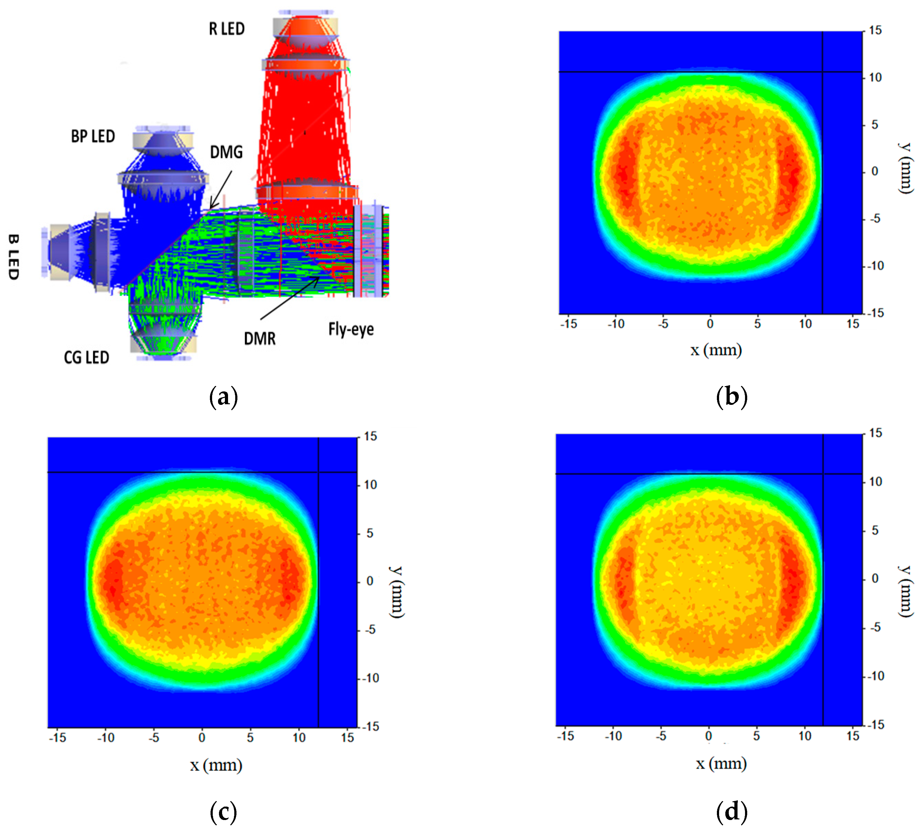
2.1. The Combiner System of 4 Channels

(a)
The design of the BP channel
The four-channel LEDs are useful to obtain high brightness for the projector, including red, converted green (CG), blue and blue pump (BP) LEDs. The CG LED consists of a BP LED chip and a glued green ceramics phosphor with a thickness of 0.15~0.25 mm. The dominant wavelength of BP LED is always from 435 nm to 445 nm, while the blue LED is from 452 nm to 465 nm. Besides the BP LED chips under the CG LED, another BP LED is designed as the fourth channel to excite the green ceramics phosphor from the frontal incidence. Therefore, the phosphors of CG LED are excited both front and back, which proves to be a 52% extra gain of green brightness. As for the fourth channel of BP LED, it is designed to illuminate the phosphor of converted green which seems like imaging BP LED onto CG LED. As shown in Figure 2a, the light from BP LED is collected by a spherical lens and an aspherical lens and then pass through the dichroic mirror of green (DMG) and two collimation lens of the CG channel. As shown in Figure 2a, the spherical lenses close to the light source are used to collect the Lambertian light from LEDs, and then aspherical lenses are adopted to form a collimating lens group to obtain near-parallel lights. Apparently, the inspired green light is reflected by the DMG and forward transmitted along the optical axis to the fly-eye. In this projection, the geometric efficiency η is up to 82% which is defined as η = ΦBP-CG/ΦBP (where ΦBP-CG is the luminous flux on the CG phosphor and ΦBP is the total luminous flux of the fourth channel of BP LED, respectively). As simulated in the system, the spot on the phosphor of CG LED is shown in Figure 2b.
The initial system architecture can be calculated [11,14] and then optimized by LightTools software. In order to reduce costs, a spherical lens is adopted to collect the rays from LEDs, and then an aspherical lens is employed to control the angle of rays. It is worth recommending that molded glass aspheric lens are needed in the CG channel when the LED lumens is high than 1000 lm for reliability. Herein, a glass material as D-ZK2 for the green channel is adopted with the reflective index nd of 1.58095 and a dispersion coefficient of 59.22. The red light collimated by three lenses is reflected by the dichroic mirror of red (DMR), which fold the light path. Similarly, the first lens located close to the Red LED is a spherical lens, while the rest are aspherical lenses in the channel. The schematic for the design of the combiner system and the spots on the fly-eye of red, green, and blue light are displayed in Figure 3. As a result, the geometric efficiency η = Φfly-eyeLED for three channels is up to 98%, where the Φfly-eye is the luminous flux on the Flye-eye and ΦLED is the total luminous flux of the LED. Besides, P1MR LEDs (Osram) with higher emitting lumens are adopted to achieve higher brightness by 25% compared with P1MQ LEDs.

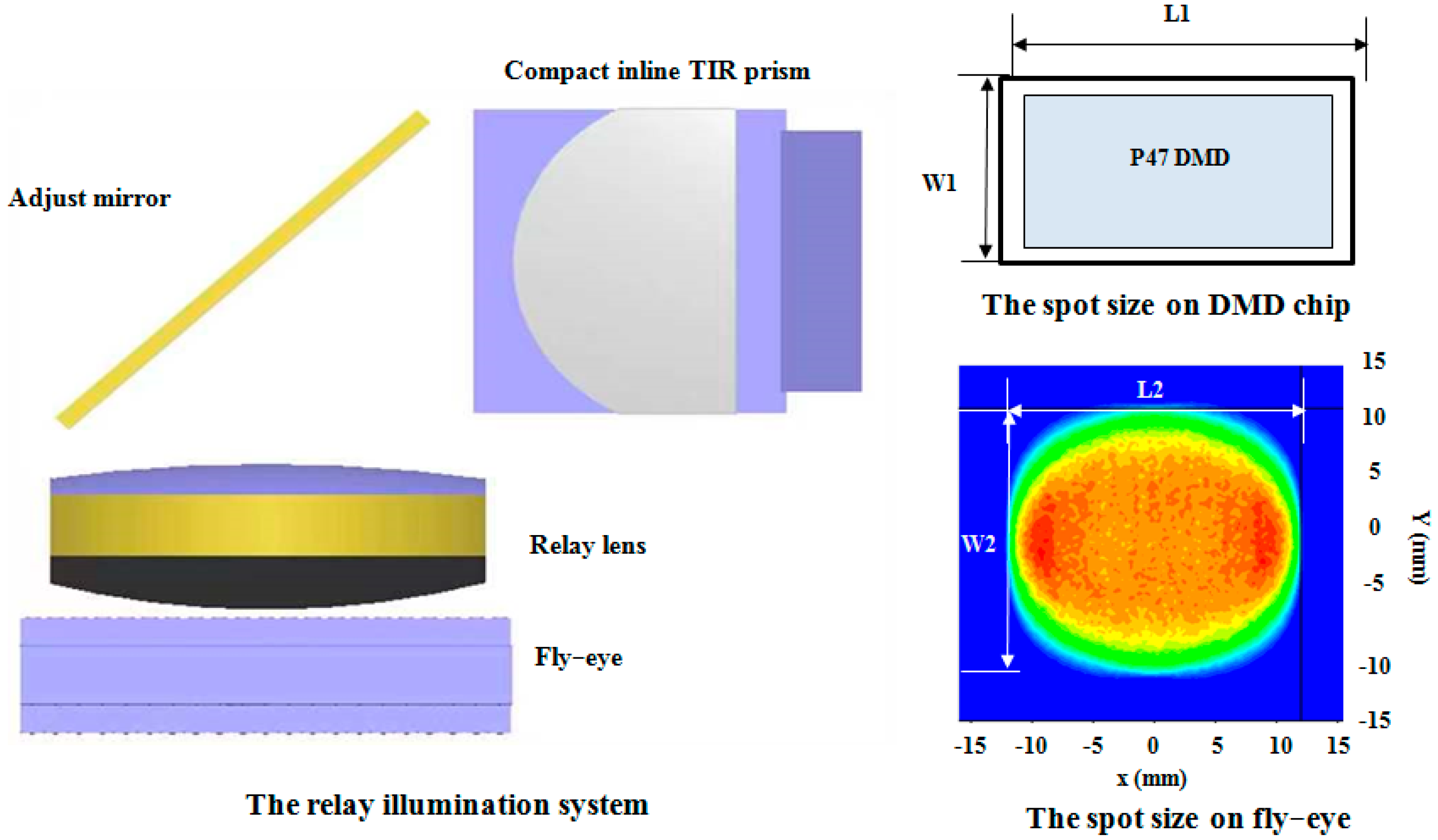
2.2. The Relay Illumination System

(a)
The design of the fly-eye
The fly-eye is an important optical element to connect the combiner system and the relay illumination system with high efficiency and uniformity. There are many rectangle cells with the same radius on both sides of the fly-eye. Every cell is designed to amplify the spot to cover the DMD. The simplified E’tendue conservation law is presented in Equation (1).
E tendue = π S   sin 2 ( θ )
Equation (1) is decomposed into two-dimensional Lach invariants, as follows, to calculate the length and width:
L 2 sin ( θ L ) L 1 sin ( θ D M D )
W 2 sin ( θ W ) W 1 sin ( θ D M D )
where L2 and W2 are the length and width of the spot on the fly-eye, respectively, L1 and W1 are the length and width of the spot on the DMD chip, respectively, and θL and θW represent the incident angles on the fly-eye, which is roughly calculated to obtain the original design goals of combination system. More detailed optimizations will be performed by the LightTools software. The size of the Pico P47 DMD chip is 10.368 × 5.832 mm2. Practically, we must design the spot to more than 10.868 × 6.332 mm2 to cover the cumulative tolerance, including lens dimension tolerance, machining structure tolerance, and assembly tolerance. Most importantly, it is useful to avoid the color band on the screen, which exhibits unexpected color on the edge of the screen. As the specification requirement of the P47 DMD chip by Texas Instruments (TI), the tilt angle of the DMD chip is 17° which means θDMD is 17°. In this projection, the material of the fly-eye is 350R with a refractive index nd is 1.50941 instead of the expensive glass fly-eye. The large area of the fly-eye is useful to reduce the power density and avoid burning up in long-time use. Therefore, the recommended angle is less than 7.6° in length and 5.3° in width with the fly-eye’s size of 24 × 20 mm2. The focus length of the fly-eye can be calculated based on Equation (4) [11,22]:
f = n r 2 ( 1 n ) ( 2 n r n d + d )
where n is the refractive index, r is the radius of the cell, and d is the thickness of the fly-eye. Therefore, we can balance the thickness and radius of fly-eye between the size of the cell without affecting the whole system. It is known that the number of cells should be minimized to decrease the cost of fly-eye. At the same time, the overall fly-eye needs to be larger in order to get lower energy density. In general, a commercial projector needs to take both into account to get a cost-effective product.
(b)
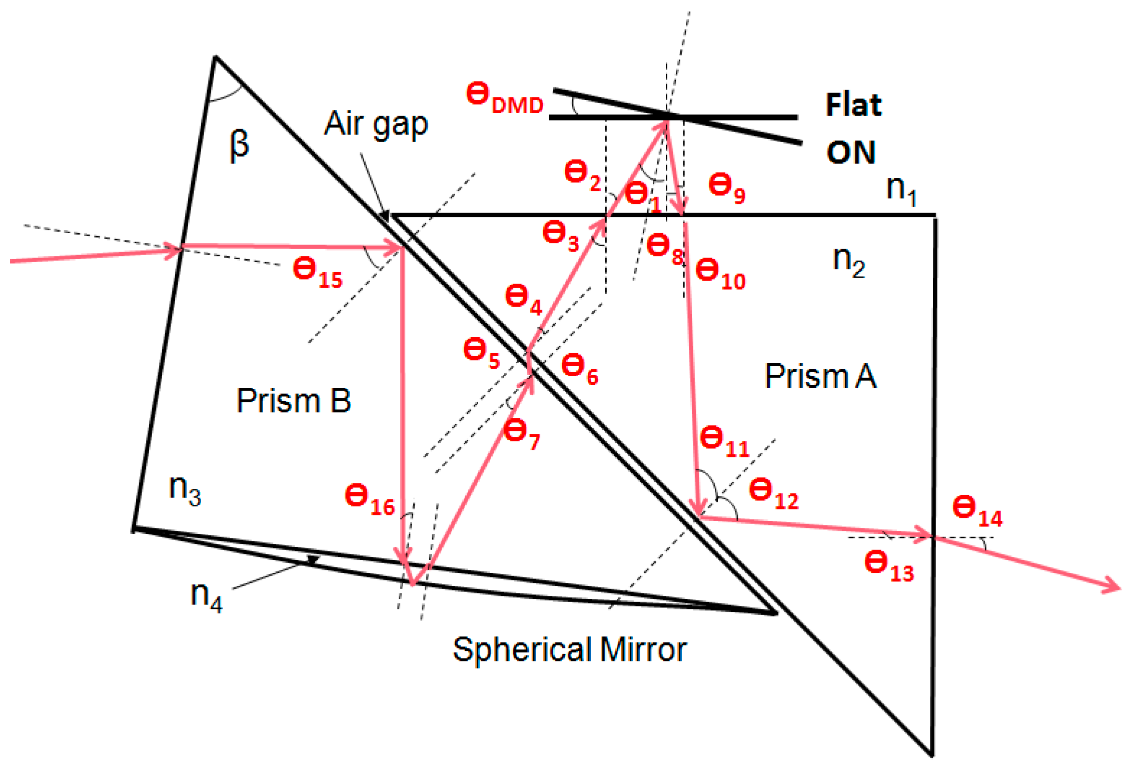
The design of a compact inline TIR prism and relay illumination system
The compact inline TIR prism uses a spherical mirror lens glued on the prism instead of a flat mirror, which effectively reduces a lens L1 on the relay lens group. Generally, the thickness of a lens is about 6 mm, and the spacing between the front and back is about 1 mm, respectively, so the overall system can be reduced by about 8 mm. The optical path length between the lens to DMD also refrains the diameter of the lens. Generally, closer to DMD results in a smaller lens diameter. However, its tolerance will be more sensitive and should be cut and glued carefully. In this system, the diameter of the spherical mirror 1.5168 is 25 mm, and the clear aperture is only half of it. Herein, H-K9L glass with an index of 1.5168 and a dispersion coefficient of 64.2 is selected as the material of the spherical mirror with a reflective coating on the outside. Further, the H-ZF4A glass with an index of 1.7283 is selected as the material of Prism A, where its dispersion coefficient is 28.32. The H-ZLAF53B glass with an index of 1.8340 and dispersion coefficient of 37.21 is selected as the material of Prism B to satisfy the total reflection on the interface. The chief ray trace of the novel prism is drawn succinctly in Figure 4. Obviously, the rays from fly-eye irradiate into a relay lens, the prism B and totally reflect at the interface of prism B and the air gap. They then enter into the spherical mirror avoiding the total reflection between prism B and a spherical mirror, reflected by the outer reflecting film to the DMD chip through the spherical mirror, prism B, air gap, and prism A orderly. Considering the total reflection and batch assembly of prisms, the air gap between prism A and prism B must be greater than 10 μm. Additionally, in order to improve transmittance and reduce reflectivity, glue with a refractive index between 1.45 and 1.60 is filled between the spherical mirror and prism B.
It is worth noting that the angle of the prism is calculated as the restrain condition during the design process [22]. When the F/# of the system is 1.7, cone angle θ is calculated as Equation (5),
F = 1 2 sin ( θ )
As per the specification description of the P47 DMD chip, the angle of θDMD is 17°and the chief ray of illumination is required to be 34°. Thus, the illumination angle of θ1 is 34° ± 17°. Based on the law of total reflection, the total reflection angle is calculated by Equation (6):
N sin ( θ ) = n 1
where N represents the reflective index of the prism, and n1 is the reflective index of air. Thus, we can obtain all the key angles listed as Equations (6)–(11) when the angle θ1 is greater than 2 × θDMD.
θ 3 a r c sin ( n 1 / n 2 sin ( θ 1 ) )
θ 7 a r c sin ( n 2 / n 3 sin ( θ 3 ) )
θ 11 45 ° + a r c sin ( n 1 / n 2 sin ( θ 1 2 θ D M D ) )
θ 15 a r c sin ( n 1 / n 3 )
θ 16 a r c sin ( n 4 / n 3 )
However, when the angle θ1 is smaller than 2 × θDMD, θ9 is on the other side of the interface normal, so Equation (9) can be written as:
θ 11 45 ° a r c sin ( n 1 / n 2 sin ( 2 θ D M D θ 1 ) )
Obviously, the angle of θ3, θ7, and θ16 must be less than the total reflection angle, while θ11 and θ15 must be bigger than the total reflection angle. When the light is not totally reflected but directly through the lens to the screen, the contrast of the projector will be dramatically decayed. Therefore, it is strongly recommended that the angle here has to be more than 2°greater than the total reflection angle.
After careful design and optimization, the relay illumination system is constructed by a relay lens, adjustable mirror, and the compact inline TIR prism, as shown in Figure 5. The DMD chip is placed underneath the prism, which is not drawn in Figure 5. The spot size on fly-eye and DMD chip is plotted, which is used to calculate theoretical goals for the combiner system by Equations (2) and (3). The adjustable mirror is designed to fold the light path into an “L” shape and compensate for the tolerance of structural parts and assembly errors in mass production. The spherical glass lens on prism B requires a small volume due to its proximity to the DMD and improves the transmittance between itself and prism B by the glue water. Consequently, compared with the common system, the relay illumination system uses only one relay lens with low cost and small volume, which exhibits high feasibility and application potential in state-of-the-art commercial projectors.

2.3. The Projection Lens

The L-shaped telecentric system can be easily compatible with a variety of projection lenses, such as short-focal lenses, telephoto lenses, and ultra-short focal lenses. As for the domestic market, the telephoto lens is more economical and practical. Herein, a projection lens is designed and optimized with F/# 1.7, a throw ratio of 1.2, and an imaging range from 60 inches to 120 inches. The total number of lenses in this projection lens is nine, and the total length is 110 mm. The MTF and curvature of the field at the projection distances of 2125 mm for a screen of 80 inches are analyzed and shown in Figure 6a. The corresponding field curvature/distortion diagrams and later color are displayed in Figure 6b. The graphs show that the MTF is higher than 0.6 at 93 lines, while the distortion is lower than 1%. In addition, as for the home application scenario, the offset between the projection lens to the DMD is 100% which is determined as Offset = d1/(H/2), where H is the height of the DMD chip, and d1 is the distance between the center axis of DMD to the axis of the projection lens.

3. System Simulation and Analysis

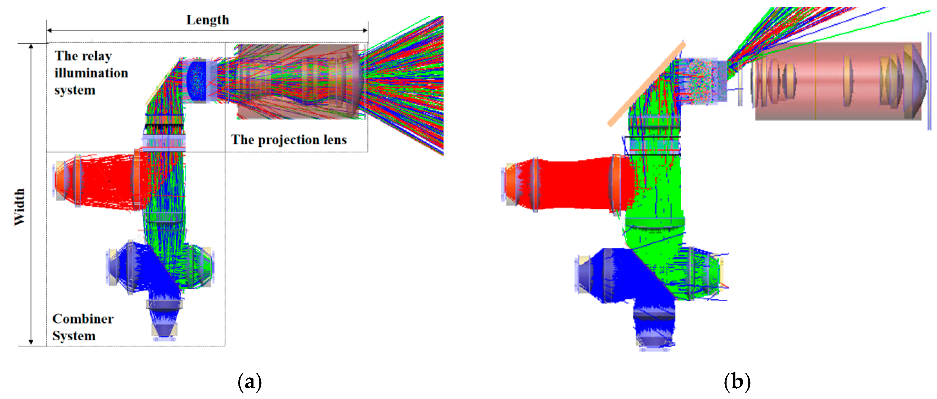
3.1. System Modeling and Simulation

The schematic diagram of the projection system is shown in Figure 7a, which integrates the combiner system, the relay illumination system and the projection lens all together. The RGB rays from the LEDs are collimated by the lenses and incident into the fly-eye, while the fourth channel of BP LED is designed to illuminate and pump the phosphor of CG LED. Then the RGB rays pass through the spherical relay lens, adjust the mirror and the novel inline TIR prism with glued spherical mirror as the relay illumination system to illuminate the DMD chip efficiently and uniformly. When DMD is ON−state as shown in Figure 7a, the rays will be reflected into the projection lens, and so the pictures on the DMD will be imaged on the screen. On the contrary, when DMD is OFF−state as shown in Figure 7b, the rays will be reflected in the specific corner direction and need to be absorbed by the black sprayed main body to avoid it into the lens. Obviously, the width of the engine is determined by the width of the relay illumination system when folded as an “L” shape. The compact inline TIR prism is helpful in reducing the width by about 8 mm by replacing the relay lens with a glued lens in the optical path.

3.2. The Simulation Performance on DMD and Screen

The luminous flux efficiency and uniformity on the DMD and screen are vital to analyzing the projector engine. The optical efficiency of ΦDMDLED reaches 87%, where ΦDMD is the luminous flux on the DMD and ΦLED is the total luminous flux of the LEDs. Meanwhile, it is important to control the color band on the screen, as shown by the border in Figure 8a. However, it needs to balance the optical energy out of the DMD chip lower than 10% to keep the high efficiency on the screen. As for the angle distribution on DMD, the horizontal angle is 17~51°, and the vertical angle is −17~17°, which matches the F/# 1.7 of the projection lens perfectly, as simulated in Figure 8b. After being composed as a whole optical system, the optical efficiencies of R, G, and B lights are 61.6%, 61.5%, and 60.5% on the screen, respectively. In the simulation, the dominant wavelengths we use are 620 nm in red, 550 nm in converted green, and 455 nm in blue. The uniformity is calculated to be 96% on the DMD chip, which shows the uniformity of 94.5% on the screen, as shown in Figure 8c. The uniformity is defined as E5/EAVE, where E5 and Eave are the luminous flux on the center point and the average of nine points on the screen of 80”, respectively.

4. Prototype Verification

Considering the coating transmittance estimation, DMD actual reflectivity and duty loss in the real prototype, the luminous flux efficiency of the whole engine can be estimated. The white color coordinates Wx and Wy will affect the luminous output flux dramatically. Here, (0.29, 0.31) is adopted for the best skin color and image quality. Once the color coordinate of Wx is smaller and the Wy is bigger, the brightness of the system will be higher. The LEDs of P1MR provided by Osram are adopted to get high luminous flux with an emitting area of 5.0 mm2. The chief coefficients of the optical path are listed in Table 2, which presents that the optical system will output the luminous flux of 1420 lm when the four channel LEDs have luminous outputs of 174 lm at 23.3 W for red, 1186 lm at 92.2 W for green, and 60 lm at 34.5 W for blue, respectively. Besides, LED lumens represent the brightness of LEDs at the temperature of 25 degrees. In particular, there is a 52% green light gain as 406 lm contributed by the fourth channel of BP LED. Considering the wall thickness of the main structure and DMD heat sink, the volume of the optical engine is 210 × 167 × 60 mm3. Comparatively, some products that adopt RTIR architecture [25] are produced in the projection market with a width of 175 mm and a thickness of 76 mm. The length of the optical machine is related to the layout of each channel and is generally close to each other. Obviously, this system has significant volume advantages in terms of thickness and width. As for the other points, the brightness of the optical engine in the market [19,25] is about 1100~1300 lm at the same test conditions, and the color gamut is 80~85%, the uniformity is 85~90%, and contrast is about 300:1~400:1. Overall, for the P47 DMD series products, this architecture has the advantages of high brightness, small volume, high contrast, high color gamut and high uniformity which shows excellent application potential in the projection market with high resolution.
In order to test and verify the performance of the projector, a projector prototype is built and measured. As shown in Figure 9a, the white state and uniformity are tested on the measure tooling. Figure 9b shows the color scale and grayscale of the projection. According to the measurement results, the total luminous flux on the screen of 80” is 1412 lm, the uniformity reaches 94.5%, and the color gamut is 84% of NTSC. The 4K resolution of 3840 × 2160 in the projector engine is tested by the picture shown in Figure 9c. It requires all the lines and words to be clear without chromatic aberration, all the displayed colors to be vivid, and the color charts to be smooth. The photo of the prototype without a cover is shown in Figure 9d. The contrast ratio of this prototype is 420:1, which is measured and calculated by the luminance on the center of the white field divided by the black field. The test results show that the prototype has a good display effect and meets practical application needs.
As for the thermal study, due to volume limitations, the temperature of R LEDs is generally controlled at 50 degrees, while the temperature of CG, BP, and B LEDs is generally controlled at 65 degrees in the center of the board. Based on the fluctuation of +/−5 degrees at the reference temperature, the brightness variation curves of R, CG, and B LEDs with temperature are shown in Figure 10. Since the contribution of CG to white field brightness accounting for about 83.5%, the white field brightness variation is about +/−2%.

5. Conclusions

In conclusion, a design of compact and high luminance 4K DLP projection based on a P47 DMD chip produced by Texas Instruments (TI) consisting of four channel combiner system, the relay illumination system, and a projection lens is proposed. As for the combiner system, the fourth channel with BP LED is described in detail, which can realize the optical efficiency of 82% illuminating on converted green (CG) LED and prove to be a 52% gain of green brightness in the prototype. Besides, LEDs with higher emitting lumens as P1MR, are adopted to get more brightness on the screen. In the relay illumination system, a compact inline TIR prism with a spherical mirror is designed in the projection, which is useful to reduce the optical machine width by about 8 mm and the thickness by about 16 mm. After the optimization of the projection lens, the modulation transfer function (MTF) of the projection lens is higher than 0.6 at 93 lines for 80” at the distance of 2125 mm, and the distortion is lower than 1%. By the simulation with 500 W rays, the R, G, and B optical efficiency of the simulated projector is 61.6%, 61.5%, and 60.5% on the screen, respectively. The total luminous flux on the screen is simulated by the total efficiency of the optical projection system and reaches 1420 lm with the input powers of Red LED of 23.3 W, CG LED of 47.0 W, Blue LED of 34.5 W, and BP LED of 45.2 W, respectively. Finally, a 4K DLP projector prototype is built and measured for further verification, which provides a luminous flux of 1412 lm with a uniformity of 94.5% and a volume of 210 × 167 × 60 mm3. Compared with the products in the market [19,25] with 4K resolution, it has significant advantages of high brightness, small volume, high contrast, high color gamut and high uniformity. It proves to be that the proposed optical engine has compact volume and high luminance, which exhibits high feasibility and application potential in the domestic portable projection market.

Author Contributions

Conceptualization, S.P., Z.Z. and Y.L.; methodology, S.P.; validation, S.P.; supervision, Y.L.; writing—original draft preparation, S.P.; writing—review and editing, S.P., Z.Z. and Y.L.; funding acquisition, S.P., Z.Z. and Y.L. All authors have read and agreed to the published version of the manuscript.

Funding

This research was funded by the Project of Science and Technology of Sichuan Province (No. 2020YFG0453) and the Project of Science and Technology of Chengdu (No. 2020YFG0279). This work also was sponsored by the Sichuan Province Key Laboratory of Display Science and Technology.

Institutional Review Board Statement

Not applicable.

Informed Consent Statement

Not applicable.

Data Availability Statement

Not applicable.

Conflicts of Interest

The authors declare no conflict of interest.

References

  1. Cox, M.A.; Drozdov, A.V. Converting a Texas Instruments DLP4710 DLP evaluation module into a spatial light modulator. Appl. Opt. 2021, 60, 465–469. [Google Scholar] [CrossRef] [PubMed]
  2. Gong, C.; Mehrl, D. Characterization of the Digital Micromirror Devices. IEEE Trans. Electron Devices 2014, 61, 4210–4215. [Google Scholar] [CrossRef]
  3. Jia, H.; Zhang, J.; Yang, J.; Li, X.; Hu, W. A novel optical digital processor based on digital micromirror device. Proc. SPIE 2008, 6837, 68370C. [Google Scholar] [CrossRef]
  4. Dudley, D.; Duncan, W.; Slaughter, J. Emerging Digital Micromirror Device (DMD) Applications. Proc. SPIE 2003, 4985, 14–25. [Google Scholar] [CrossRef]
  5. Huang, J.-W. Optical design of ultrashort throw liquid crystal on silicon projection system. Opt. Eng. 2017, 56, 051408. [Google Scholar] [CrossRef]
  6. Lazarev, G.; Bonifer, S.; Engel, P.; Höhne, D.; Notni, G. High-resolution LCOS microdisplay with sub-kHz frame rate for high performance, high precision 3D sensor. Proc. SPIE 2017, 10335, 103351B. [Google Scholar] [CrossRef]
  7. Lin, J.-S.; Hsu, H.-C.; Chang, M.W.; Liu, C.-p. RGB LED illuminator for LCOS panel display. Proc. SPIE 2005, 5942, 59420Y. [Google Scholar]
  8. Yu, Z.; Hao, H.Q. New PBS multilayer design for LCOS projector. J. Appl. Opt. 2012, 33, 153–158. [Google Scholar] [CrossRef]
  9. Catelani, M.; Ciani, L.; Barile, G. A new design technique of TFT–LCD display for avionics application. Microelectron. Reliab. 2012, 52, 1776–1780. [Google Scholar] [CrossRef]
  10. Chen, E.; Zhao, Y.; Lin, S.; Cai, J.; Xu, S.; Ye, Y.; Yan, Q.F.; Guo, T. Design of improved prototype of two-in-one polarization-interlaced stereoscopic projection display. Opt. Express 2019, 27, 4060–4076. [Google Scholar] [CrossRef]
  11. Jiang, H.; Lin, Z.; Li, Y.; Yan, Y.; Zhou, Z.; Chen, E.; Yan, Q.; Guo, T. Projection optical engine design based on tri-color LEDs and digital light processing technology. Appl. Opt. 2021, 60, 6971–6977. [Google Scholar] [CrossRef] [PubMed]
  12. Zhao, X.; Fang, Z.-l.; Cui, J.-c.; Zhang, X.; Mu, G.-g. Illumination system using LED sources for pocket-size projectors. Appl. Opt. 2007, 46, 522–526. [Google Scholar] [CrossRef] [PubMed]
  13. Sun, W.-S.; Chiang, Y.-C.; Tsuei, C.-H. Optical design for the DLP pocket projector using LED light source. Phys. Procedia 2011, 19, 301–307. [Google Scholar] [CrossRef]
  14. Li, D.; Zhang, B.; Zhu, J. Illumination optics design for DMD Pico-projectors based on generalized functional method and microlens array. J. Eur. Opt. Soc.-Rapid Publ. 2019, 15, 11. [Google Scholar] [CrossRef]
  15. Shin, S.; Jung, Y.; Ahn, T.-J.; Jeong, S.; Lee, S.-G.; Choi, K.-Y. The Compact Systems Design Based on DMD and the Straight Line 2-Channel LED for a Mobile Embedded Pico Projector. J. Disp. Technol. 2012, 8, 219–224. [Google Scholar] [CrossRef]
  16. Pan, J.-W.; Wang, C.-M.; Lan, H.-C.; Sun, W.-S.; Chang, J.-Y. Homogenized LED-illumination using microlens arrays for a pocket-sized projector. Opt. Express 2007, 15, 10483–10491. [Google Scholar] [CrossRef]
  17. Pan, J.W.; Tu, S.H.; Wang, C.M.; Chang, J.Y. High efficiency pocket-size projector with a compact projection lens and a light emitting diode-based light source system. Appl. Opt. 2008, 47, 3406–3414. [Google Scholar] [CrossRef]
  18. Boer, D.; Bruls, D.; Jagt, H. High-brightness source based on luminescent concentration. Opt. Express 2016, 24, A1069–A1074. [Google Scholar] [CrossRef]
  19. Xgimi Technology Co., Ltd. Available online: https://shop.xgimi.com/goods/1211100779.html (accessed on 3 May 2023).
  20. Keuper, M.H.; Harbers, G.; Paolini, S. 26.1: RGB LED Illuminator for Pocket-Sized Projectors. SID Symp. Dig. Tech. Pap. 2004, 35, 943–945. [Google Scholar] [CrossRef]
  21. Hung, C.-C.; Sun, J.-H.; Tzeng, Y.-F.; MacDonald, J.; Lai, W.C.; Li, S.-X.; Fang, Y.-C.; Sun, H.-C.; Chen, Y.-L. A study of extended optimization of U-type rod for LED projectors. Optik 2011, 122, 385–390. [Google Scholar] [CrossRef]
  22. Bai, X.; Jing, X.; Liao, N. Design method for the high optical efficiency and uniformity illumination system of the projector. Opt. Express 2021, 29, 12502–12515. [Google Scholar] [CrossRef] [PubMed]
  23. Pan, J.-W.; Lin, S.-H. Achromatic design in the illumination system for a mini projector with LED light source. Opt. Express 2011, 19, 15750–15759. [Google Scholar] [CrossRef] [PubMed]
  24. Texas Instruments (TI). DLP® Discovery Optics 101 Application Note. Available online: http://focus.ti.com/lit/an/dlpa022/dlpa022.pdf (accessed on 3 May 2023).
  25. Dang Bei Technology Co., Ltd. Available online: https://item.jd.com/46337738328.html (accessed on 3 May 2023).
Figure 1. The diagram of relay illumination systems of optical projection engine with RTIR prism architecture (a), TIR prism architecture (b), inline TIR Prism (c), and a compact inline TIR prism (d).
Photonics 10 00559 g001
Figure 2. (a) Schematic of the BP channel and (b) the spot size on the phosphor of CG LED. (b) The RGB channels in the combiner system.
Photonics 10 00559 g002
Figure 3. Schematic for the design of combiner system (a), and the spot size on fly-eye of red (b), green (c), and blue (d) channels.
Photonics 10 00559 g003
Figure 4. Schematic of the compact inline TIR prism.
Photonics 10 00559 g004
Figure 5. Schematic of the relay illumination system.
Photonics 10 00559 g005
Figure 6. Design results of the imaging projection lens group: (a) MTF curves at the screen of 80”, (b) field curvature diagrams, and (c) distortion diagrams.
Photonics 10 00559 g006
Figure 7. System modeling simulation and analysis. The ray tracing of (a) DMD ON-state and (b) DMD OFF-state of the projection engine.
Photonics 10 00559 g007
Figure 8. System modeling simulation and analysis. (a) Illumination distribution on DMD, (b) angle distribution on DMD, and (c) illumination distribution on the screen.
Photonics 10 00559 g008aPhotonics 10 00559 g008b
Figure 9. The prototype testing, (a) white and uniform test, (b) color scale and grayscale test, (c) 4K resolution test, and (d) a photo of the prototype.
Photonics 10 00559 g009
Figure 10. The influence curve of temperature on the brightness of LEDs.
Photonics 10 00559 g010
Table 1. Comparison of RTIR prism, TIR prism, Inline prim, compact Inline Prism architectures.
RTIR prismTIR PrismInline PrismCompact Inline Prism
VolumeBigBigMediumSmall
BrightnessModerateHighHighHigh
ContrastModerateModerateHighHigh
UniformityModerateModerateHighHigh
Design complexityEasyEasyMediumHigh
Table 2. Simulated Total Efficiency of the Projection Optical Engine.
ItemsRedGreenBlue
Duty33%38%29%
LED lumens21138546978
LED power (W)23.347.0 (BP 45.2)34.5
Optical efficiency on the screen61.6%61.5%60.5%
BP pump contribution on CG/152%/
Coating transmittance estimation
(18 lenses and prism)
65%60%54%
DMD actual reflectivity68%
Duty loss96%
Output luminous flux174118660
Color coordinate(0.69, 0.31)(0.33, 0.61)(0.14, 0.03)
Total luminous flux1420
White color coordinate(0.29, 0.31)
Disclaimer/Publisher’s Note: The statements, opinions and data contained in all publications are solely those of the individual author(s) and contributor(s) and not of MDPI and/or the editor(s). MDPI and/or the editor(s) disclaim responsibility for any injury to people or property resulting from any ideas, methods, instructions or products referred to in the content.

