1. Introduction
The interest in optical healthcare sensor technologies has significantly increased in recent years. This research focuses on evaluating non-invasive pulsatile signals from the brain and their correlation to changes in physiological parameters such as intracranial pressure (ICP). The latter is the main clinical parameter evaluated in neurocritical care for several pathologies prone to hypertensive events, such as traumatic brain injury, hydrocephalus, brain tumours, stroke haemorrhages, among others [
1,
2]. The authors consider that changes in intracranial pressure will affect the morphology of the optical pulse, meaning that the rigorous analysis of quantifiable features of the pulsatile signals could enable the development of a computational model to non-invasively estimate the absolute values of intracranial pressure [
3,
4]. As a prerequisite for understanding such a relation between the optical signals and ICP, it was deemed necessary to innovate a controlled in vitro environment comprising an advanced head/brain vascular phantom.
The main contributions of this work are:
A novel brain phantom that enables the frequent and systematic acquisition and evaluation of cerebral pulsatile optical signals utilising non-invasive optical sensors.
An anatomical model that mimics tissues’ optical properties for a reliable interaction with optical sensors.
Bespoke technology that allows the controlled interrogation of the brain under various haemodynamic protocols, especially during cases of increased intracranial pressure, which is the primary focus of this research.
A better understanding of cerebral fluid dynamics and brain–light tissue interaction.
An alternative to studies where no clinical data are available.
A versatile head phantom enabling the simulation of different clinical scenarios that cannot be induced in healthy volunteers or routinely found in patients (e.g., intracranial hypertension).
Up-to-date literature does not provide a detailed description of a complete head model that involves optical tissue properties, the human anatomy, and physiological changes. Authors such as Afshari, Correia and Kurth have reported research outcomes on mimicking the optical properties of some head layers [
5,
6,
7], however, they do not provide an anatomical model of the head or a cerebrospinal fluid (CSF) circulation system. Other researchers have focused their work on replicating the CSF to mimic changes in intracranial pressure [
8,
9], however, these phantoms would not allow the acquisition of optical signals from the forehead as the skulls presented in these studies are pressurised inside a box. Moreover, accurate anatomical models have been created from healthy adult magnetic resonance images [
9], especially for developing MRI-compatible or CT-scan-compatible phantoms [
10,
11,
12]. Other anatomical models such as the Circle of Willis has been copied to a rigid vascular model for phantom studies and the computational analysis of blood flow [
8,
13]. Similarly, other cardiovascular studies have analysed the velocity profiles and pulsatile flow while simulating vessels and blood mechanical properties [
14,
15]. Additionally, additional anatomical structures have been included by other authors, such as ventricles, meninges, scalp, skin and hair [
8,
9,
12]. Although the phantoms presented in the literature successfully achieved their designated purpose, this paper aimed to describe the design, manufacturing process and performance tests of a comprehensive vascular head phantom that allows the acquisition of pulsatile optical signals (Photoplethysmograms (PPGs)) from the cerebral cortex arteries while various physiological parameters are controlled.
2. Materials and Methods
2.1. Skull Development
The head consists of the skull with its coverings and contents, including the brain with a group of meningeal layers at the inside and a scalp layer on top [
16]. The phantom skull was produced using a pre-existing computational model consisting of three parts: the calvaria, the maxilla and the mandible. The model was downloaded from the medical library of a free access site (
www.grabcad.com, accessed on 20 March 2020). The STL files of the calvaria and the maxilla were scaled down to correspond with the size of an adult human skull (67.5% of the original model size). The maxilla model was edited in SolidWorks 2020 to fill the anatomical foramina and canals. The calvaria is the part of the skull formed by the frontal, occipital and parietal bones, where optical measurements, utilising a non-invasive sensor would probably take place. Consequently, the calvaria must replicate the optical properties of a real skull, which is not a requirement for the maxilla, as no optical measurements would be performed in this area. The calvaria was printed using the Form 2 printer from Formlabs (Somerville, MA, USA) in a resin (RS-F2-GPCL-04) that enables a good visibility of the brain. All standard Formlabs’ resins have comparable material properties to those reported in the cranial bone. For instance, evidence reports a tensile strength of the human skull of 67.73 Mpa, which is close enough to the tensile strength of the phantom’s resin (65 Mpa) [
17]. Moreover, according to McElehaney, the human skull elastic modulus ranges between 2.41 and 5.58 GPa; in comparison, Formlabs resin has an elastic modulus of 2.8 GPa, which is in the range reported by McElehaney [
18]. However, other authors have found a higher value for the skull’s elastic modulus (mean: 8.51 Gpa); therefore, the phantom resin would be somewhat more compliant than the actual cranial bone [
19]. The 3D printing of the scalp took approximately 11 h to print, considering a printing resolution of 0.05 mm. After completion, the support structures on the 3D printed part were removed, washed in isopropyl alcohol for 30 min and post-cured in a UV chamber at 60 °C for 15 min. The resin developed a yellowish colour after cure.
As the maxilla dimensions exceeded the Form2 printing volume, this part was manufactured in a bigger 3D printer. Hence, the Objt30 Pro (Stratasys, MN, USA) Printer was used to make the maxilla in a transparent PolyJet™ photopolymer called VeroClear™. This part (maxilla) took approximately 64 h to print, considering a printing resolution of 0.016 mm. After completion, the gel-like support structures (SUP705) were removed from the printed part. To remove the excess support material surrounding the model, it was soaked in a 1% solution of sodium hydroxide for 1 h. To improve the material’s finish and transparency, the model was exposed to 24 h of photobleaching, as intense florescent lighting can reduce the yellow tint by over 90%. For the latter process, a house-made chamber was built with aluminium foil and two 45 W, 6500 K table lamps. The final result of the maxilla is illustrated in the results section.
In order to secure the head phantom in place on a bench during the experiments, two clamps were designed in Autodesk Netfabb Premium 2019 using operational tools and were 3D printed in VeroClear™. Each clamp consisted of a two-part structure: one was screwed to a metallic base and supported the bottom of the skull zygomatic arch, while the second part clamped the top of the arch following its geometry. Both parts of each clamp were put together with a nylon screw while holding the zygomatic arch.
As one of the aims of the phantom is the simulation of haemodynamic events, the insertion of access ports in the calvaria was needed. The calvaria design was created in SolidWorks 2020, which included nine female Luer-ports on the external surface. As a standardised system, Luer-ports allowed leak-free connections between the female and a large range of mating male connectors by rotating one over the other. Additionally, two of the Luer-ports ended as Luer-ports at the interior of the calvaria, where they were connected to the arteries, embedded within the brain phantom at the inside of the skull. One was used as the entrance of the circulatory system, and the other at the exit. Moreover, two of the ports at the top of the calvaria were placed at the right and left Kocher points, where external ventricular drains (EVDs) are commonly inserted in clinical practice. EVDs provide continuous intracranial pressure monitoring and cerebrospinal fluid diversion [
20], making Kocher’s point the optimal place to insert the invasive ICP sensor in the phantom too. Anatomical measurements were also performed to locate each hemisphere Kocher’s point, 11 cm posterior to the phantom nasion and 3 cm lateral to the midline, equivalent to the mid-pupillary line [
21]. Finally, two more ports were placed in the frontal bone, another one at each parietal bone and one more in the higher portion of the occipital lobe over the midline. These final five ports were included for multiple purposes, including the connection to the CSF circulatory system and the future simulation of intracranial haemorrhages.
The final step of the skull design and manufacture was the seal between both parts, namely the calvaria and the maxilla. This process is essential to simulate pathophysiological scenarios such as intracranial hypertension. The seal consists of an external compression structure attached to the phantom base. The structure involves a clamp designed from the calvaria’s surface and a lead screw, both parts attached by a prisoner’s nut. The clamp was printed on the Objt30 Pro in a black colour PolyJet™ photopolymer. The clamp compresses the calvaria against the maxilla to keep both parts together. The clamp’s height is set by the position of the lead screw, which is controlled by a thumb nut. The compression is distributed by the clamp through all the calvaria’s area in order to ensure a uniform seal. A thick (2 mm) silicone gasket was placed between both parts to ensure the seal. A two-layer acrylic mould was manufactured by a laser cutter and is held together by metallic clamps. The material used for the gasket was Sylgard 180, which was mixed by hand with its catalyser in a proportion of 10 to 0.6 g, respectively. The mix bubbles were removed using a vacuum chamber, where the mix was exposed to −160 psi for twenty minutes. Finally, the mix took 24 h to set in the mould. The final version of the skull seal is illustrated in the results section.
The seal was tested by increasing the intracranial pressure from 0 to 30 mmHg. The ICP was sensed using an invasive needle tip pressure transducer (Gaeltec Devices Ltd., Dunvegan, UK) and its control unit (Neurolog system NL109, Digitimer, Welwyn Garden City, Hertfordshire, UK). The sensor was placed on the right Kocher’s point port while the pressure was increased by a syringe through a second port at the top of the calvaria. The presence of leaks was visually checked, and the capacity of the phantom to preserve a stable ICP value for longer than five minutes confirmed a good seal.
2.2. Brain Phantom Development
The brain was developed using moulding and casting techniques. The brain mould was developed from a human brain model with arteries (C20 [1017868]) manufactured by 3B Scientific (Hamburg, Germany). According to the information provided by the company, the part was modelled from a healthy specimen in its real size. While the age and sex of the human sample are unknown, the model might belong to an adult man. The latter conclusion was made, given that the model volume is approximately 1250 cm
3 and the average adult brain volume is 1260 cm
3 for men and 1130 cm
3 for women [
22,
23,
24]. Additionally, the brain model size was used as the reference to scale the skull STL files, as was mentioned before. Therefore, the brain phantom fitted perfectly in the printed skull and allowed enough space to simulate a CSF intracranial volume of 150 mL, which corresponds to the average volume reported in the literature [
25,
26,
27].
A two-part mould of the brain anatomical model was created using PolycraftTM GP-3481-F Silicone Rubber and PolycraftTM GP-3481-F Silicone Clear Catalyst. Initially, a double box of Perspex was designed in SolidWorks 2020 and cut in a laser cutting machine. The design consisted of a tabbed box of 12 cm × 15 cm × 17 cm that fit precisely inside a second glued box. The latter had a 5 cm diameter hole at the bottom of the box that served to push the internal box during the demoulding process. Once the box was ready, the brain model was covered with a medium-duty silicone releaser (Ambersil, Formula 6), and it was held from the medulla with a universal clamp attached to a support stand. The brain anatomical model was located in the middle of the box and suspended in the air. Separately, a 2.2 Kg of PolycraftTM RTV-3481 base was mixed with 220 g of PolycraftTM GP-3481-F Silicone Clear Catalyst. The mix was then poured into the box all around the brain model until it was completely covered. After 24 h, the brain was demoulded by pushing the internal box through the hole of the external one. Once the tabbed box came out, each wall was easily removed, and the silicone mould was ready to be cut. A surgical scalpel was used to split the mould into two halves, following the cerebral midline. A zigzag cut shape helped align the mould.
The inside of the mould was then sprayed with a medium-duty silicone releaser (Ambersil, Formula 6, Gloucester, UK), and both parts of the mould were held together. The mould was put inside an aluminium foil tray before the brain silicone mixture was poured through the hole on the top of the mould. The brain mix consisted of a silicone gel (Sylgard 527, DOWSIL—Dow Corning, Midland, MI, USA), as this material resembles the mechanical properties of the brain under dynamic and static conditions [
8,
9]. The casting mixture was prepared by adding two-part silicone gel in a ratio of 1:1. As the silicone gel is transparent with minimal scattering properties, titanium dioxide (TiO
2) particles with a primary crystal size of 550 nm (Altiris 550, Venator Corporation, Teesside, UK) were added in the mixture in a ratio of (weight/volume) of 0.1 g/100 mL to simulate near-infrared scattering. The solution of Sylgard 527 and titanium dioxide particles were then hand-mixed and sonicated for ten minutes. The mix went into three vacuum chamber cycles before undergoing a degassing cycle for another 10 min (i.e., to remove air bubbles which may cause optical heterogeneities within the phantom). After an initial curing cycle in the oven for 4 h at 125 °C, the silicone phantom was removed from the casting and placed in the oven at 125 °C for one extra hour.
2.3. Brain Vasculature Implementation
The most common non-invasive technologies implemented to interrogate the brain are near-infrared spectroscopy (NIRS) and transcranial Doppler (TCD) [
28]. TCD typically interrogates the middle cerebral artery, which is the largest branch of the internal carotid, and mainly supplies the lateral surface of the temporal and parietal lobes. Additionally, many cerebral imaging evaluations, such as computerised tomography scans and magnetic resonance images, assess the middle cerebral artery to define the cerebral blood flow, flow velocity, and cerebral infarction after trauma [
29]. Although the phantom was not designed for TCD measurements or diagnostic images, as it includes the middle cerebral artery into the brain circulation, given its clinical relevance. Moreover, the phantom should mimic some blood circulation to allow the assessment of NIR pulsatile signals from the brain. NIRS technologies do not interrogate a particular artery of the brain, instead, these assess arterial, venous and capillary blood. However, commercial NIRS devices are usually located on a patient’s forehead; hence, most of the evidence on this topic is based on frontal lobe measurements. In consequence, the phantom included a representation of the anterior cerebral arteries (ACAs), which are responsible for supplying the frontal lobe.
In order to replicate the vasculature in the brain phantom, a group of tubes were passed through the phantom brain. Polydimethylsiloxane (PDMS) tubes were fabricated with the novel technique of continuous dip-coating proposed by Nomoni et al. [
30]. This technique has shown good results in acquiring photoplethysmographic (PPG) signals from a pulsatile tissue phantom. The phantom’s middle cerebral artery consists of a tube with an inner diameter of 3.2 mm, placed at 3 mm from the parenchyma surface. The artery dimension corresponds to the of value 3.1 ± 0.4 mm, measured in 100 patients’ MCA by CT angiography in Rai’s study [
31]. Three anterior cerebral arteries (ACAs) were also fabricated with an internal diameter of 2.2 mm, corresponding with the value of 2.09 mm as reported in the literature [
32]. The ACAs were placed on the frontal lobe of the brain phantom, leaving 4 mm of parenchymal tissue over each artery and a two-millimetre separation from each other.
In this phase of the research, extracerebral circulation was not included; hence, the phantom lacks a scalp.
2.4. Head Phantom Optical Properties
As one of the aims was to assess the optical properties of the materials chosen to build the head phantom, the spectra of the brain and skull materials were collected using a Lambda 1050 dual-beam spectrophotometer from Perkin Elmer Corp. (Waltham, MA, USA). A 100 mm InGaAs integrating sphere detector set at 0 deg was used for the detection of diffuse reflectance and diffuse transmittance measurements. The spectra were acquired in the wavelength range and interval as the resin, yet the analysis was focused on the wavelength range 660–900 nm, the same as where pulseoxymetry and cerebral NIRS devices work. The absorption contribution of chromophores, such as oxygenated and deoxygenated haemoglobin, is maximised in this spectral range, while the absorption contribution of other compounds, such as water molecules, is minimised [
33]. The skull sample (6 × 10 × 20 mm) was 3D printed following the aforementioned procedure to manufacture the calvaria, and it was placed into a UVette
® plastic cuvette. Similarly, the brain sample (10 × 10 × 20 mm) was fabricated as a small batch of the brain’s recipe and placed into a cuvette to protect the sample from damage. Spectra collection and visualisation were performed using the software packages: UVWin Lab for LAMBDA 1050 from Perkin Elmer (Waltham, MA, USA). The optical properties were characterised using the inverse adding doubling (IAD) approach based on diffuse reflectance and total transmittance measurements of samples in an integrating sphere spectrophotometer [
34].
2.5. Actuation Systems and Fluids
A cardiovascular closed-loop system was designed to create a pulsatile flow through the brain arteries. The system consists of a pulsatile pump that simulates the heart and some PVC Clear Vinyl tubes that carry the blood from the heart to the phantom’s brain and back. The Harvard Apparatus 55-3305 (Holliston, MA, USA) was used to simulate the heart’s pumping action [
35]. Moreover, the vessels are involved in the cardiovascular circuit, where the pump’s outlet feeding the artificial ascending aortic vessel (ID = 20 mm, length = 124 mm) [
36,
37]. A single tap of the ascending aortic vessel feeds the left common carotid artery (ID = 6 mm, length = 136 mm) [
38,
39]. Likewise, the common carotid artery is continued by the left internal carotid (ID = 4 mm, length = 86 mm) [
38,
39], which is connected to the phantom brain arteries. The outlet of the phantom is plugged into the jugular vein (ID = 14 mm [
40]) before returning to a seal cardiotomy/venous reservoir (Affinity pixie, Medtronic, Minneapolis, MN, USA). The reservoir has a maximum capacity of 1200 mL and allows a flow rate of up to 7 L/min, which supplies enough artificial blood to the circulatory system. It has also been considered that there is an angle of 30° and a distance of 346 mm between the head phantom and the heart, as some studies have assessed the effects of head elevation in the care of head-injured patients [
41,
42].
The pump allows changes in stroke volume between 15 and 100 mL and changes in heart rate from 10 to 100 beats per minute. Finally, the systolic phase can be adjusted from 35 to 50% of the total cycle [
35]. This pump is specialised for large animal haemodynamic studies using blood. However, handling tissue and blood is a complicated, limited process, requiring monitoring and controlling multiple variables such as pH, temperature, flow and gas dilution. This research investigated a new artificial blood recipe to mimic the optical properties of blood to enable a more rapid and replicable evaluation of an optical technology using a phantom. In 2015, Akl et al. reported a dye solution capable of mimicking the extinction spectra of haemoglobin in the NIRS range [
43]. The primary dyes of Akl’s solution were India ink, Cyan ink and Epolight 2735, which served as absorbers between approximately 700 nm and 950 nm. Unfortunately, Epolight’s manufacturer (Epolin, Newark, NJ, USA) removed the reference ‘2735’ from the market, precluding the exact recipe reproduction.
In order to mimic the blood’s optical behaviour, a mix of two solutions with different light absorption at red and infrared wavelengths were needed. The first one should allow more infrared light to pass through and should absorb more red light (660 nm), which can simulate deoxygenated haemoglobin (cyan ink). The second solution should absorb more infrared light (940 nm) and should allow more red light to pass through, mimicking oxygenated haemoglobin (epolight). Consequently, the recipe proposed by Akl et al. for deoxygenated haemoglobin was implemented. A 0.226% v/v of India Ink served as offset and was mixed with 4.17 % v/v of Inkjet Photo Cyan dissolved in phosphate-buffered saline (PBS, 0.1 M pH 7.4).
On the other hand, the Epolight reference ‘2057’ was used to replace the Epolight 2735 due to their similar spectra, with a maximum absorption close to 990 nm. The dye reported by Akl et al. could be diluted in water, while every other Epolight reference with a peak absorbance in the near-infrared can only be diluted in chemical solvents such as acetone, alcohol or ether. Therefore, for the oxygenated haemoglobin recipe, the phosphate-buffered saline was replaced by 1-Methoxy-2-propanol (98.5%, density = 0.92 g/mL), in which 300 mg/L of Epolight 2057 was diluted. The dye was slowly added into the solvent using magnetic stirring.
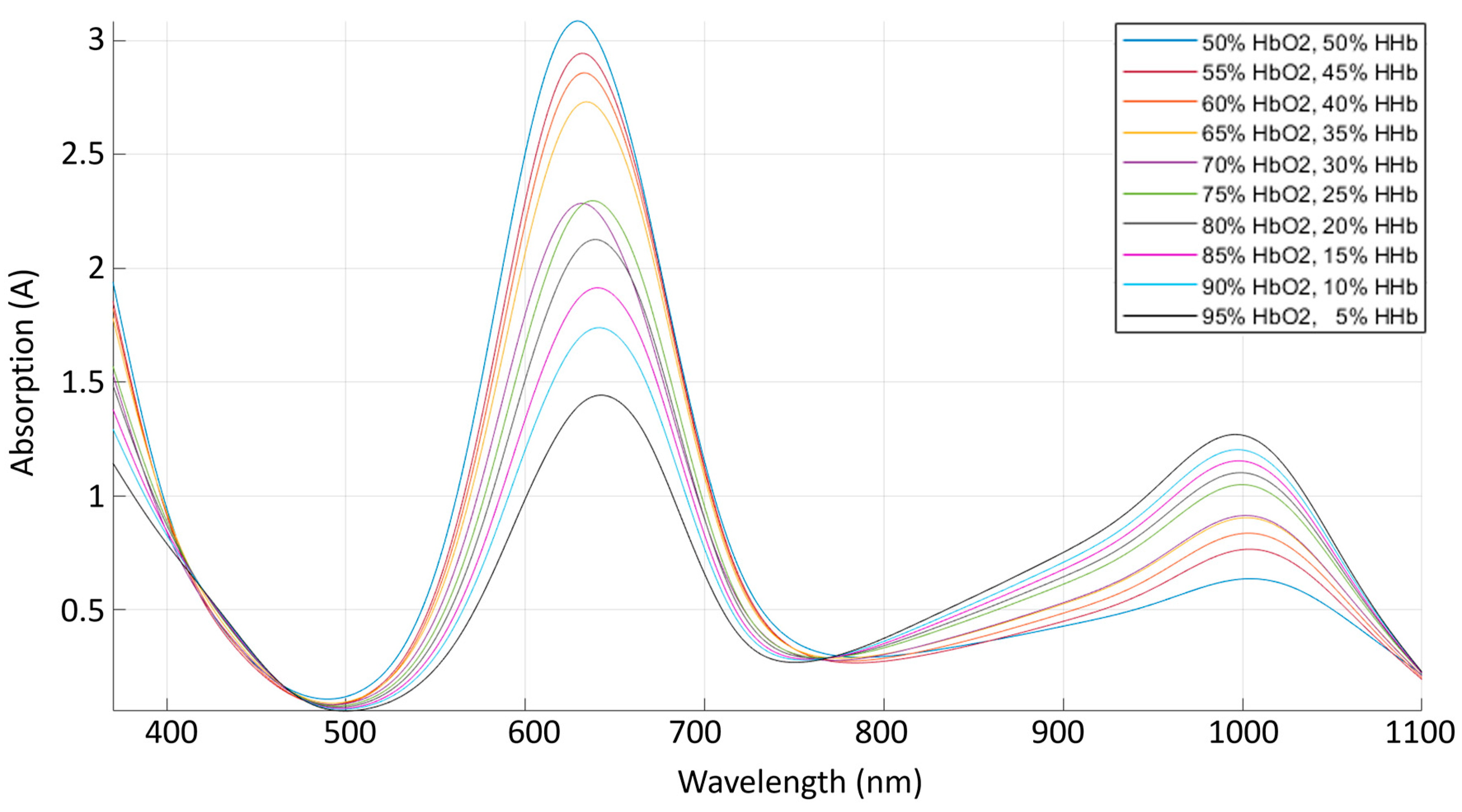
Both mixtures (HbO2/Hb) were mixed in different ratios, starting at low levels (50/50%) and progressively increasing in 5% steps until a ratio of 95/5%. The absorbance spectra of these mixtures were collected using a Lambda 1050 dual-beam spectrophotometer from Perkin Elmer Corp (Perkin Elmer Corp, Waltham, MA, USA).
In addition to the blood circulatory system, the phantom simulates changes in intracranial pressure due to its relevance in neuromonitoring. The pressure inside the skull rises when the intracranial volume overcomes the skull capacity due to oedema, haemorrhages or an increase in CSF. In the current phantom design, intracranial volume changes are induced by epidural haemorrhages and alterations in CSF volume. To mimic CSF, this has been implemented using the artificial CSF KIT produced by EcoCyte Bioscience (Dortmund, Germany). The KIT consists of a two-part solution, part A and part B, to produce 1000 mL of artificial CSF. Part A (50 mL) is mixed with 900 mL of deionised water, then part B (50 mL) is slowly added, and the mix is oxygenated with oxygen at 95%. This commercial recipe of artificial CSF contains NaCl (125 mM), KCl (3 mM), CaCl (22.5 mM), MgSO4 (1.3 mM), NaH2PO4 (1.25 mM), NaHCO3 (26 mM) and glucose (13 mM). To preserve the optimal conditions of the artificial CSF, it was kept in constant circulation through a cooler system under 8 °C.
The CSF circulatory system involves a programable two-syringe pump (Legato 180, KD Scientific Inc, Holliston, MA, USA) that can infuse and withdraw fluid at rates as low as 0.58 pl/min. Considering that normal CSF production has a rate of 0.3–0.4 mL/min (500 mL/day) [
44,
45], one 20 mL syringe is programmed to infuse 18 mL in 1 h to mimic real CSF production conditions in the head phantom. Additionally, CSF is constantly reabsorbed by the arachnoid granulation in the subarachnoid space, which keeps the CSF intracranial volume within 90–150 mL. Therefore, the second syringe is programmed to withdraw CSF from the phantom head accordingly with the simulated scenario. The pump controls the flow and direction of the fluid, from a cooling reservoir into the head phantom and back. Two three-way solenoid valves were synchronised with the pump to allow such circulation.
2.6. Signal Acquisition System
Blood pressure and intracranial pressure were monitored at selected locations in the phantom. The blood pressure was monitored with a research-grade blood pressure transducer (Harvard Apparatus, Cambridge, MA, USA) at the inlet of the phantom’s aorta. The intracranial pressure was recorded in the epidural/subarachnoid space, which is the same on the phantom due to the lack of meninges. Following the gold standard for clinical ICP monitoring, a needle tip pressure transducer (Gaeltec Devices Ltd., UK) and a corresponding control unit were used to acquire invasive ICP measurements (Neurolog system NL109, Digitimer, Welwyn Garden City, Hertfordshire, UK). Measured data were transferred to a National Instruments (NI) data acquisition card (DAQ) (National Instruments, Austin, TX, USA), processed in LabVIEW and recorded on a desktop computer.
A custom-made single wavelength optical sensor was placed on the phantom’s forehead, directly above the ACAs. The sensor consists of an 810 nm wavelength emitter (current 30 mA) and a photodetector located 28 mm from the light source. The 810 nm wavelength, also known as the isosbestic wavelength, has the unique characteristic of being absorbed to the same extent by both oxy- and deoxyhaemoglobin. Therefore, it is the perfect point to record an optical signal independent of blood oxygenation that could be correlated to intracranial volumetric changes. Moreover, as explained in a previous Monte Carlo simulation paper [
46], a higher source–detector (S-D) distance allows light to travel deeper into the tissue; hence, pulsatile signals from a photodiode located at 2.8 mm should relate to volumetric information from the cerebral tissue. The optical signal was acquired through an in-house instrumentation system connected to a NI DAQ for analogue-to-digital conversion. The LabVIEW interface allowed signal visualisation and recording (Fs: 2000 Hz).
3. Results and Discussion
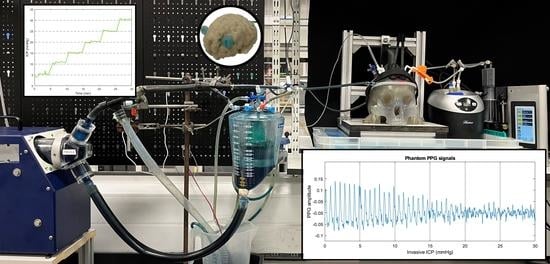
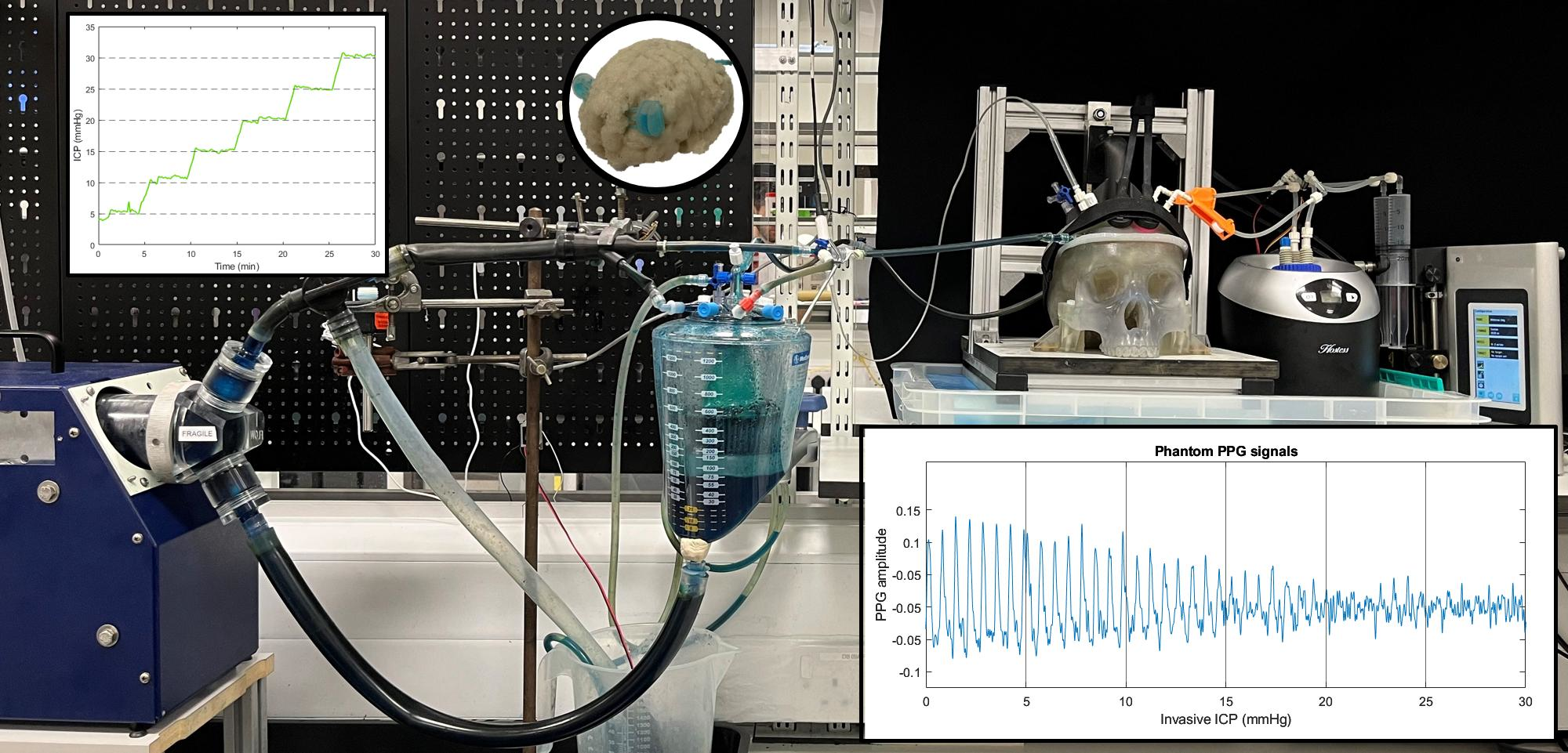
Figure 1 shows the developed head phantom and in vitro circulation system as described in the methods section.
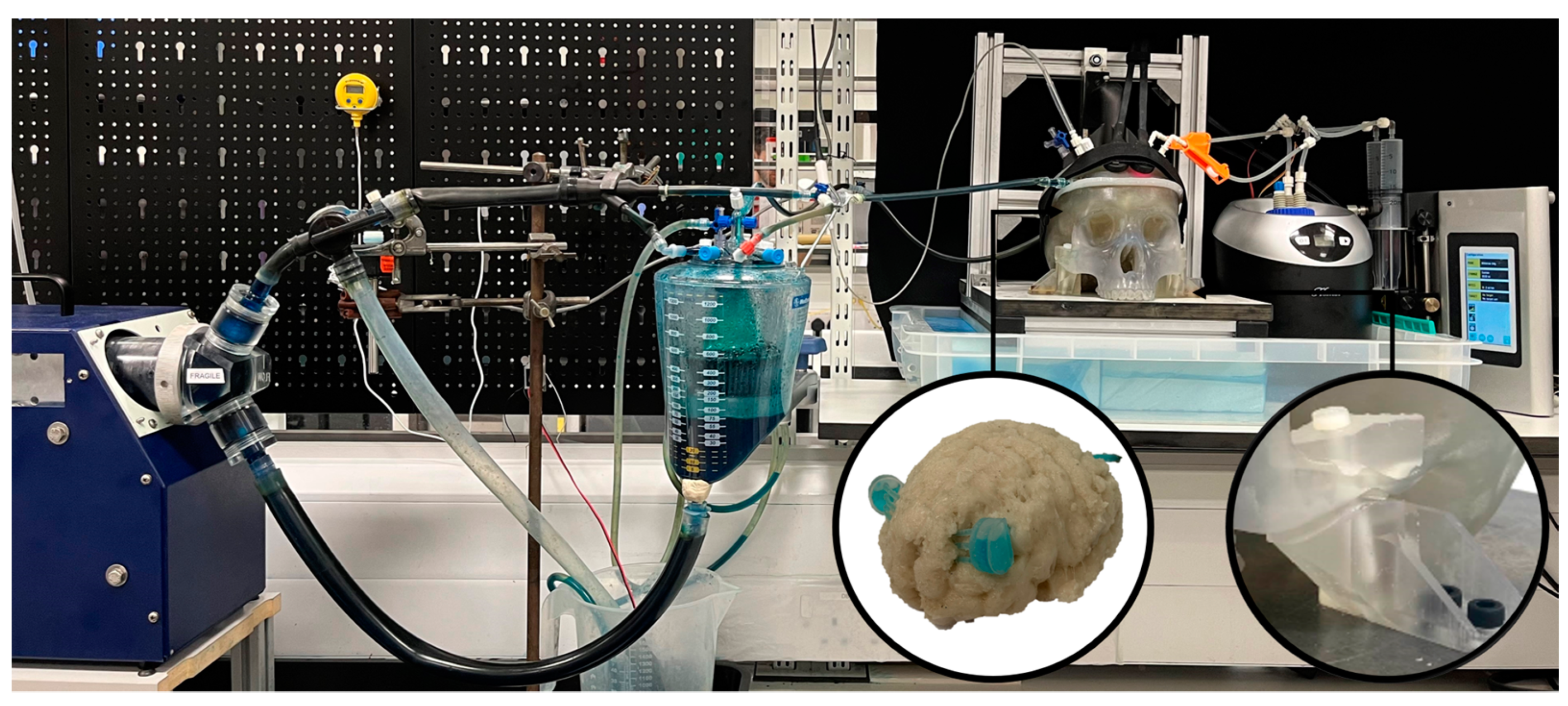
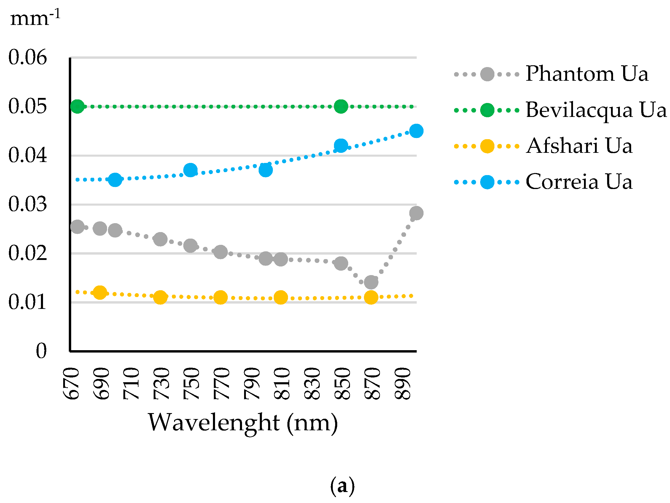
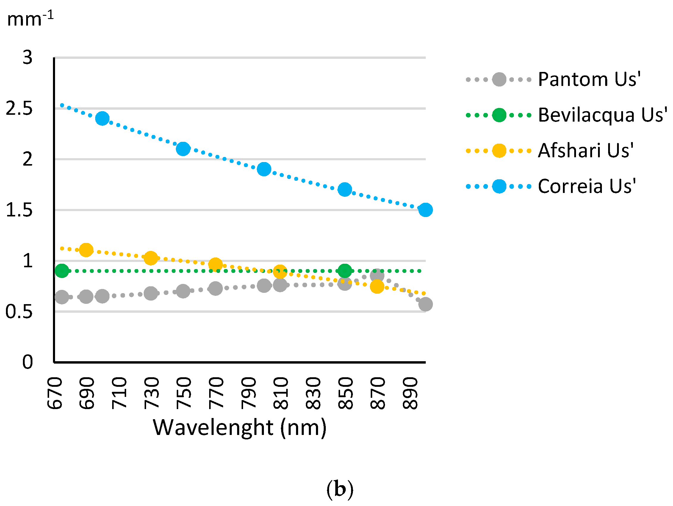
The optical coefficients of the phantom materials were compared to values reported in the literature, as shown in
Figure 2. For example, Bevilacqua reported coefficients from the human frontal lobe, while Afshari, Correia and Kurth described the optical properties of their brain and skull phantoms [
6,
7,
47,
48]. Unfortunately, Kurth did not report skull coefficients, and thus, these are only included in the brain analysis.
The absorbance coefficients of the phantom’s brain are lower than the ones reported by other authors in the literature. Nonetheless, they are very close to most authors, presenting lower differences to the values given by Bevilacqua from the human frontal lobe. Likewise, the reduced scattering coefficients within the range of interest are very close to the values reported from the most recent phantom published by Afshari in 2022 (error ± 0.3 mm
−1). A similar analysis to compare the optical properties of the phantom’s skull is shown in
Figure 3. It was found that the absorbance coefficients are within the ones reported in the literature (error ± 0.25 mm
−1). Likewise, reduced scattering coefficients are very close to the values reported by Bevilacqua and Afshari, especially at wavelengths over 770 nm. Therefore, it is believable that the phantom materials can replicate the optical properties of the brain and skull.
Following these results, this study demonstrated that both phantom materials have similar optical properties to those reported in the literature, leading to the production of both anatomical structures, as was previously described in the methods section. The resulting brain, calvaria and maxilla were successfully manufactured, as shown in
Figure 4.
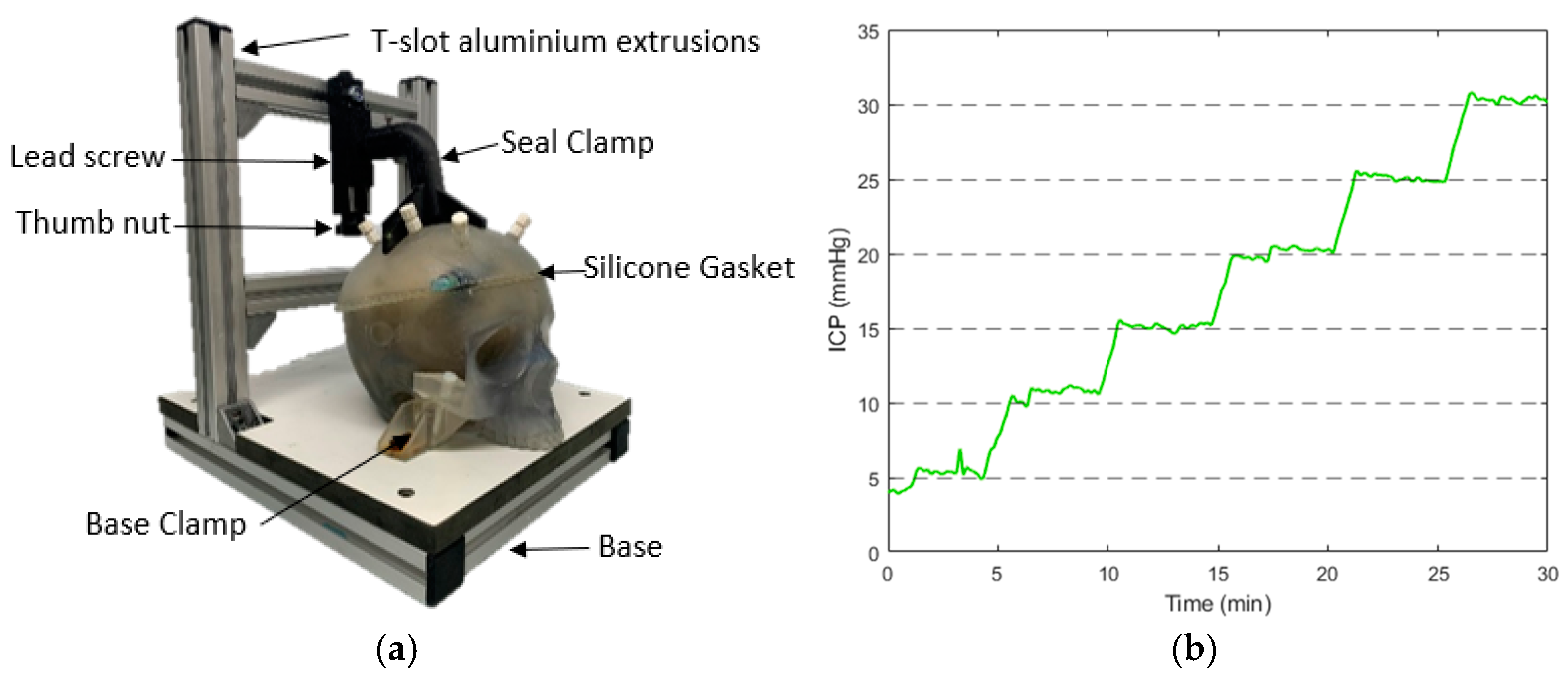
Figure 5a shows the resultant compression structure to seal the skull. This system used a custom-made clamp that matches the calvaria’s surface for a uniform distribution of the pressure. Additionally, a removable and waterproof silicone gasket worked as the contact interface between the calvaria and the maxilla, offering extra protection against leaks.
Figure 5b displays the results of the seal test, where the intracranial pressure recorded by an invasive probe was held for more than five minutes at the different pressure steps from 0 to 30 mmHg.
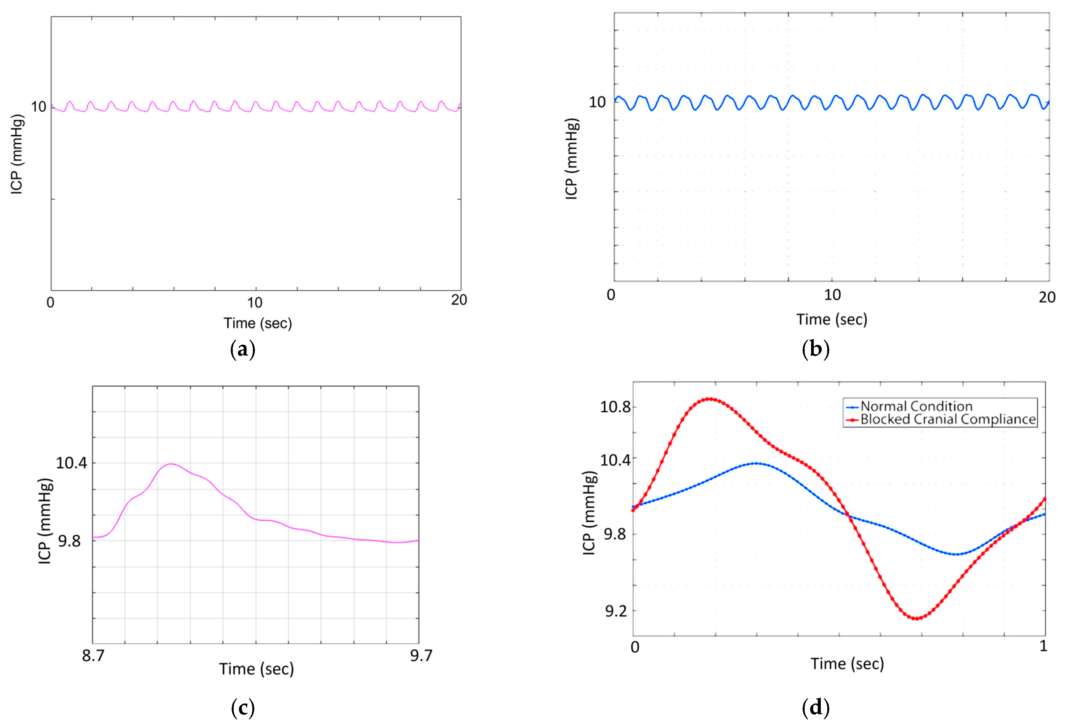
The seal and the CSF circulatory system allowed the controlled regulation of the phantom’s ICP by the infusion and withdrawal of artificial CSF from the skull. Although most invasive ICP probes report the mean value for clinical decision making, ICP is a pulsatile signal that is affected by arterial blood pressure and cerebral compliance. Therefore, this study has recorded the pulsations of the invasive ICP signals at a normal pressure value (10 mmHg) over several cardiac cycles. The results shown in
Figure 6a,d agree with the normal in vivo conditions simulated on Bottan’s phantom (
Figure 6b,c), where the pulsations amplitude of approximately 0.4 mmHg were expected [
8]. The latter demonstrates the effect of the heart pulsations in the intracranial pressure under normal compliance and healthy conditions.
In addition to the CSF system, which controls the intracranial pressure, the phantom also involves a blood circulatory system that provides a pulsatile flow to the brain arteries. Recorded signals from an invasive ABP probe at the aorta’s input are displayed in
Figure 7. The phantom mimicked normal ABP values with a mean systole value of 118 ± 8.5 mmHg and a diastole of 70 ± 8.5 mmHg. These values were calculated as the mean and standard deviation of the peaks and onset envelopes (display in zoom-in view). The resultant waveform does not have a clear dichotic notch but corresponds to a stable heart rate of 60 beats per minute. Moreover, the peak values of invasive ICP presented the same frequency as ABP pulsations.
For this circulatory system, a new dye-based fluid was developed in order to mimic the blood’s optical properties. The spectra of different dye mixtures were analysed.
Figure 8 shows the light absorption spectra of the different mixtures within the visible and near-infrared ranges. The results show an absorbance peak at 660 nm that decreases when the Epolight solution increases. On the contrary, a second absorbance peak at 1000 nm increases when the cyan solution decreases. Moreover, the absorbance stays relatively constant at 780 nm. Therefore, these mixtures have a similar behaviour as those reported for oxy- and deoxyhaemoglobin absorption in human blood, where oxygenated haemoglobin absorbs less light in the red region (600–700 nm), while it absorbs more light in the infrared region (800–1000 nm) of the spectrum. An opposite relation exists for deoxygenated haemoglobin [
49].
The later development aimed to replicate the optical, anatomical and physiological parameters of the human head that would permit the analysis of optical signals extracted from the brain arteries, which might be correlated to cerebral dynamics changes (i.e., intracranial hypertension). As the brain is surrounded by CSF, an increased pressure surrounding the cerebral arteries on the cortex surface affects the morphology of these arteries, and then, their squeezed volume could yield a different shape on the optical signal, and their morphological features could correlate with increased levels of ICP. In order to facilitate the future evaluation of such a powerful hypothesis, this study demonstrated the acquisition of pulsatile signals from the phantom cerebral arteries at different ICP values.
The custom-made optical sensor successfully acquired optical pulsations from the phantom’s cerebral arteries while the intracranial pressure was increased.
Figure 9 depicts PPGs acquired at 810 nm and a source detector separation of 2.8 cm. Visual changes in the signal amplitude could lead to a deeper investigation of this topic. Likewise, many other clinical scenarios could be mimicked in this head model by changing ABP and ICP or by introducing blood haemorrhages through the calvaria ports. It was demonstrated that the phantom’s operating parameters could be easily adapted to study pathologic intracranial dynamics. Hence, this phantom system could be useful for developing and evaluating optical technologies for interrogating cerebral physiological changes.
As in all in vitro models, the phantom at hand is a simplified representation of a very complex real system. Therefore, the design has some limitations that could lead to future optimisations. For instance, the current version of the phantom lacks a ventricular system, which is key for the simulation of pathologies such as hydrocephalus, where the volume of CSF increases in this internal cavity of the brain rather than in the subarachnoid space around the brain. This difference alters the cerebral dynamics and most probably also the morphology of the optical signals. Similarly, the current brain phantom has a fixed brain volume where oedema cannot be simulated. The future implementation of dynamic materials might allow the flexible control of the brain volume, which is directly correlated to changes in intracranial pressure.
Although this research included multiple ports in the calvaria, which can be used for the infusion of blood to mimic an epidural haemorrhage, the evaluation of light-tissue interaction due to the presence of this event has been included as part of future work. Similarly, the use of artificial blood limits the evaluation of optical technologies related to cerebral oxygenation monitoring. Hence, the future implementation of an oxygenation set-up by diluting oxygen and nitrogen into animal blood could be of interest for a broader analysis of neuromonitoring optical tools. Finally, in this phase of the research, extracerebral perfusion was not included; hence the phantom lacks a scalp. Further analysis of the interference from extracerebral blood pulsation should be included in the subsequent phases of the head phantom, providing a most realistic behaviour for optical signals.


