A Low-Complexity Joint Compensation Scheme of Carrier Recovery for Coherent Free-Space Optical Communication


State Key Laboratory of Information Photonics and Optical Communications, Beijing University of Posts and Telecommunications, Beijing 100876, China
*
Author to whom correspondence should be addressed.
Photonics 2023, 10(4), 389; https://doi.org/10.3390/photonics10040389
Submission received: 22 February 2023
/
Revised: 17 March 2023
/
Accepted: 27 March 2023
/
Published: 1 April 2023
(This article belongs to the Topic Fiber Optic Communication)
Abstract
:In this paper, a low-complexity joint compensation scheme of carrier recovery (JCSCR) for coherent free-space optical (CFSO) communication is proposed. We applied the carrier recovery joint compensation approach to a CFSO communication system in the quadrature phase shift keying (QPSK) modulation format. A signal-preprocessing stage, which effectively avoided the repetitive operations found in traditional carrier recovery schemes, was proposed. Unlike in existing carrier recovery algorithms, the modulated phase of the received signal could be accurately removed using only the sum and subtraction of real absolute values in the signal-preprocessing stage, greatly reducing the complexity of the operation. Since this algorithm avoids the traditional fourth operation, the system’s complexity is reduced while additional noise generated by fourth cross-terms would be prevented and system noise immunity would be greatly enhanced. In addition, this algorithm uses joint compensation of phase errors in the final compensation stage, further reducing the complexity of the computation of the whole algorithmic scheme. A 10 Gbps QPSK CFSO communication transmission experiment was conducted in an atmospheric turbulence channel to verify the proposed technique and improvement in receiver sensitivity.
1. Introduction
With the rapid development of space technology, a large number of high-resolution space exploration data need to be transmitted back to the ground in real time, and the communication-link-system information-transmission capacity and transmission-rate demand have increased. In this context, free-space optical (FSO) communication technology is an important research direction in the field of optical communication due to its large capacity, high bandwidth, flexible deployment, and excellent confidentiality [1,2,3,4]. FSO communication systems can be divided into two major categories: coherent free-space optical (CFSO) communication systems and noncoherent free-space optical (NCFSO) communication systems. Compared with the intensity modulation/direct detection (IM/DD) [5]-based NCFSO communication system, the CFSO system is more flexible in its modulation and has higher spectral efficiency and receiver sensitivity [6,7,8]. Therefore, CFSO communication systems are considered an effective technical approach to achieve high speed and high-capacity data transmission in FSO communication [9,10].
A CFSO communication transmission system in the signal phase is affected by the frequency offset and phase noise generated by the device itself, in addition to atmospheric turbulence that can further cause signal phase distortion, resulting in system performance degradation. An effective approach to combat this issue is to improve the receiver sensitivity of the system using digital coherent reception (DCR) techniques based on digital signal processing (DSP) to compensate for the phase of the signal at the receiver end. Traditional DSP involves two stages in the carrier-phase- recovery module. The carrier frequency offset estimation (CFOE) algorithm is used in the first stage to compensate for the frequency offset (FO) in the carrier waveform, limiting the FO to within the tolerance of the carrier phase estimation. Subsequently, carrier-phase error caused by atmospheric turbulence, laser linewidth, and ASE noise is further corrected with the help of the second-stage carrier phase offset estimation (POE) algorithm, allowing achievement of the correct judgment and demodulation of the received signal. Traditional time-domain carrier recovery modules (abbreviated 4th-PD-VV algorithm) usually use a combination of the fourth phase difference (4th-PD) method [11] and the Viterbi–Viterbi phase-estimation (VVPE) algorithm [12,13] to estimate and compensate for signal carrier frequency and phase offset. The 4th-PD-VV scheme requires separate fourth-power operations in the CFOE module and the POE module to remove the modulated phase information of a signal. This repetitive operation increases the operational complexity of the whole scheme. In addition, when the modulated phase is removed using the fourth-power operation, a large amount of additional noise appears in the cross-terms generated in the operation, which greatly reduces the noise immunity and receiver sensitivity of the system.
Designing an efficient and low-complexity carrier recovery algorithm for CSFO communication systems is a challenging task. In this paper, for the problem of high computational complexity and low noise immunity of the 4th-PD-VV algorithm, we propose a low-complexity joint compensation scheme of carrier recovery (JCSCR) for high-speed CFSO systems. This scheme’s design includes a signal-preprocessing stage that removes the modulated phase information of the signal using real-absolute-value addition and subtraction. This approach reduces the complexity of the system while avoiding the system performance impact of the additional noise generated by the fourth-power operation in the 4th-PD-VV algorithm. Finally, we propose that joint compensation of the FOE value and the POE value is used in the signal-compensation-estimation error stage, further reducing the complexity of the overall scheme. Due to the benefit of the optimization of the signal-preprocessing stage, the number of multipliers required in the operation of the proposed scheme is less than of the those for the 4th-PD-VV scheme. The simulation results of the CFSO system with the JCSCR in different turbulence channels demonstrated the improved receiver sensitivity and system noise-tolerance capability of the proposed scheme. Therefore, using the proposed technique, we can achieve lower complexity, higher noise immunity, and higher receiver sensitivity. The effectiveness and feasibility of this scheme were verified with a 10 Gbps quadrature phase-shift keying (QPSK) CFSO communication transmission system.
2. Operation Principle of the Proposed Scheme
Complex signal corruption entering a carrier recovery module is mainly the result of frequency offset between the transmitter laser and the local oscillation (LO) laser, as well as carrier phase errors caused by atmospheric turbulence, laser linewidth, and ASE noise. Other damage to the carrier signal was compensated for in the previous process module. The kth observed signal, , at the receiver can be modeled as [14]
where is the modulation phase of the kth signal, denotes the carrier FO, is the symbol duration, denotes the carrier phase noise (which includes the phase noise introduced via the laser linewidth and atmospheric turbulence), and denotes the ASE phase noise, which presents zero-mean Gaussian distribution.
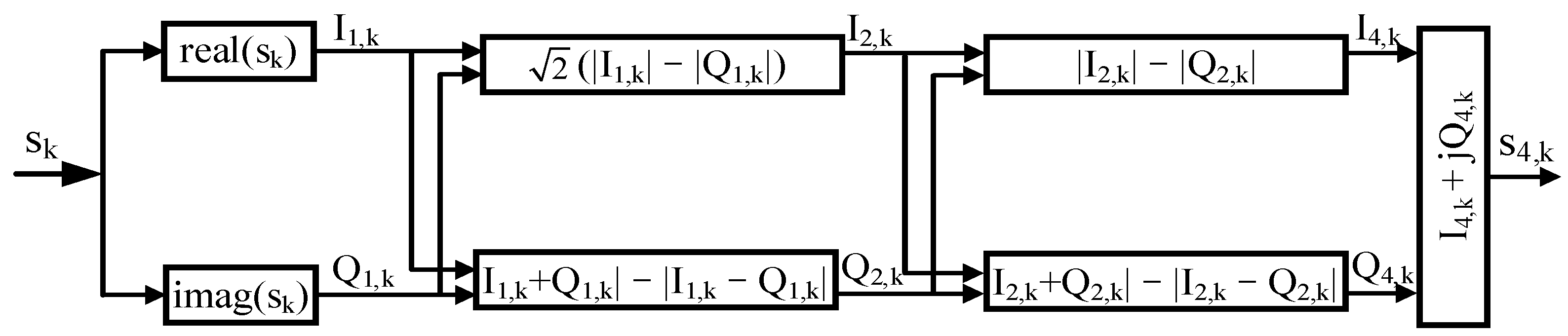
The block diagram of the proposed JCSCR is shown in Figure 1, where represents the complex signal of the kth-input carrier recovery module. In the first stage of the JCSCR, the received signal will need to be preprocessed. To remove the signal modulation phase more efficiently, we used a four-level absolute operation instead of a fourth-power operation, adding and subtracting the absolute values of the real and imaginary parts [15]. The flow chart of the first-stage phase operation is shown in Figure 2. The real function () in the figure represents the operation of the complex real part, and the imag function () represents the operation of the imaginary part; indicates that the kth output complex signal after the phase angle is expanded to four times that of the original.
For convenience of discussion, the effects resulting from additive ASE noise, , were not considered during the derivation of the first-stage equations. Analysis of will be explained later [16,17]. First, the received complex signal is operated via calculating the real part and the imaginary part:
where . We considered expanding the phase angle of the trigonometric function by a factor of two using the twofold-angle formula.
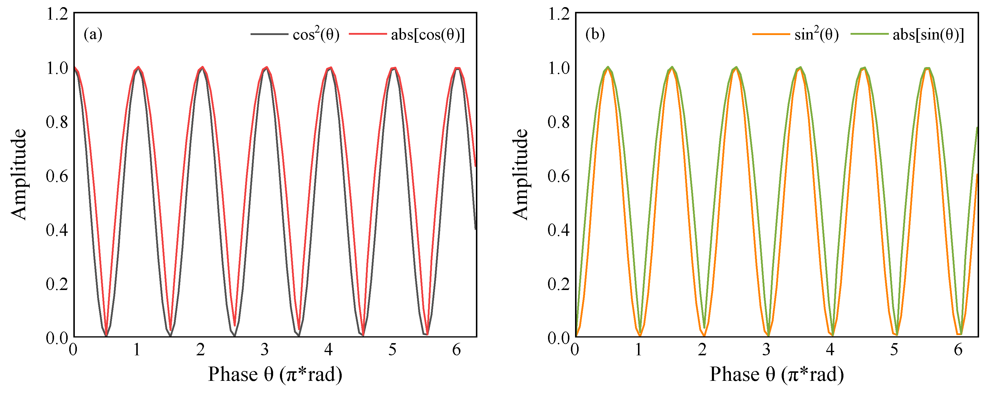
As shown in Figure 3, the square operation of trigonometric function and the absolute-value operation are very close to the waveform; they have the same period and approximate change law. To reduce the complexity of the calculation, we replaced the square operation of the trigonometric function with the absolute-value operation of the real numbers for approximation instead, realizing the twofold operation of the phase angle.
Therefore, the trigonometric bisector cosine term in Equation (3) can be approximated as follows:
The sine term in Equation (3) can be approximated with the following equation:
The cos-term coefficient of Equation (5) is multiplied by to balance with the sin-term coefficient in Equation (6); then, Equation (3) can be rewritten as
Similarly, to achieve the quadruple-phase angle, it is only necessary to perform the corresponding angle expansion operation using the above method on top of the double-phase angle. The final result was
We reassembled the real and imaginary terms into a complex signal.
Subsequently, after the preprocessing stage, the signal, enters the frequency-deviation-estimation stage. In this stage, the phase error caused by frequency deviation between the transmitter laser and the LO laser can be easily calculated as
After elimination of the effects caused by FO, the third stage of the carrier-phase-recovery module estimates and compensates for phase errors in the signal.
The POE () detection module uses two adjacent phase offset estimations for comparison. If adjacent phase offset estimations jump, a phase period is compensated [18]:
where .
The actual final compensated POE in the proposed scheme is
Finally, the final phase offset estimation, , and the frequency offset estimation, , derived from the previous frequency offset estimation module are jointly compensated into the received signal.
It should be noted that random fluctuations in the amplitude and phase of the received signal, caused by refractive index changes due to atmospheric turbulence, usually have frequencies between 20 Hz and 1 kHz [19,20]. In a CFSO transmission system with a communication rate on the order of GHz, the phase noise variation caused by the laser linewidth and atmospheric turbulence will vary relatively slowly, and its influence of two adjacent symbols can be considered the same [19,21].
The fourth-power operation was nonlinear; after this fourth-power operation, Equation (1) generated many cross-multiplication terms containing the signal and ASE noise. In taking the power of two as an example——only the first term is a useful signal; the remaining terms can be regarded as amplified noise. This means that the fourth-power operation will expand system noise and the 4th-PD-VV algorithm is less resistant to noise. On the contrary, the absolute-value operation of real numbers in the proposed scheme can directly offer sign judgment without generating cross-multiplication terms, so it has less impact on subsequent modules during the carrier recovery. Additionally, instead of viewing FOE and CPE as two separate processing flows in the proposed scheme, a preprocessing stage was chosen to be added prior to the conjugate multiplication of the CFOE. In this stage, four-level absolute-value operation is performed to remove the signal-modulation-phase operation. The preprocessed signal is fed to the subsequent carrier recovery compensation module. This approach avoids the repetitive four-level absolute-value operation of the CPE module in the third stage and minimizes the complexity of the whole scheme. Finally, the scheme uses joint compensation of the FOE and the CPE. This approach reduces the number of multipliers used, which further reduces the complexity of the scheme.
3. Simulation Demonstration and Performance Evaluation
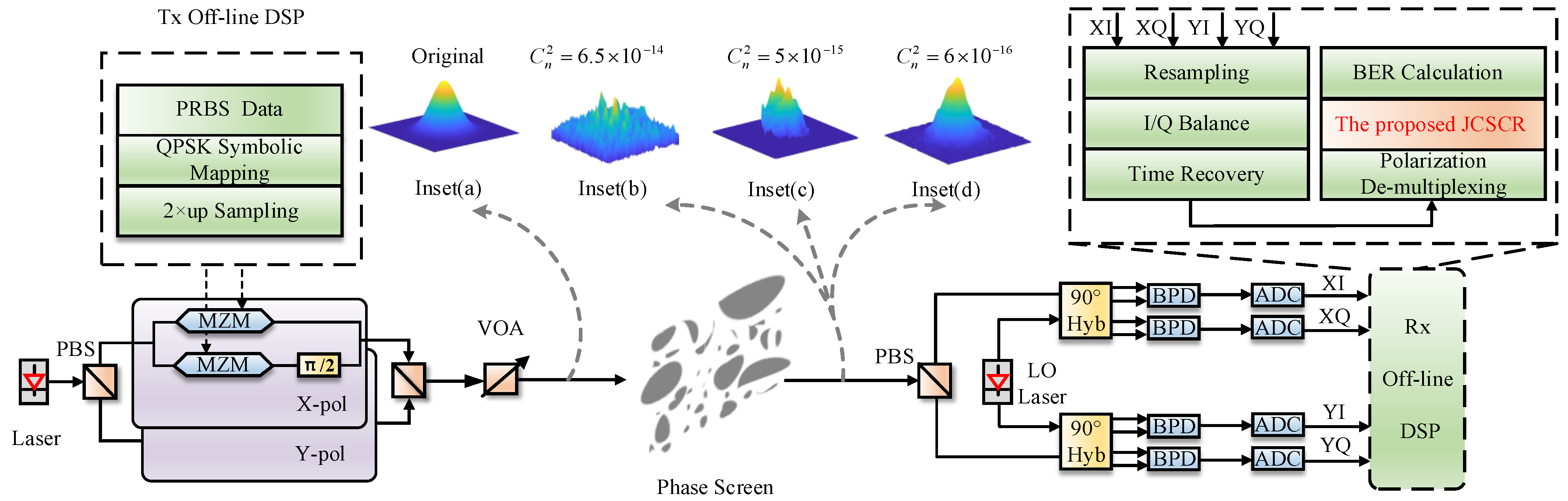
The simulation platform of a 10 Gbps QPSK CFSO communication system is shown in Figure 4. Firstly, the PRBS data source was mapped to QPSK symbols in the mapping module and then converted to corresponding electrical pulse signals. The transmitter side used a polarization beam splitter (PBS) to split the external cavity laser (ECL), with a linewidth of 50 kHz, into two orthogonally polarized lights. The four electrical pulse signals of the two polarization states drove two dual parallel Mach–Zehnder modulators (MZMs) to complete the up-light modulations of the two orthogonally polarized lights. The modulated optical signals of the two polarization states were coupled with a polarization beam combiner (PBC) to form a signal beam and were then integrated into a computer-simulated free-space turbulence channel. To simulate different transmitting optical powers, we used a variable optical attenuator (VOA) to adjust the appropriate input power on the transmitter side. On the receiver side, a continuous wave laser with a linewidth of 50 kHz was used as the LO laser, with a frequency offset of 300 MHz from the transmitter-side laser. Finally, the four electrical signals were mixed and balanced with the integrated optical coherent receiver. The detector was sampled with an analog-to-digital converter (ADC) and processed in an offline DSP module. The offline DSP module included IQ quadrature imbalance compensation, clock recovery, polarization demultiplexing, JCSCR, QPSK de-mapping, and BER counting.
In computer simulations of free-space turbulence channels, the McGlamery atmospheric-turbulence phase-screen model based on the Fourier transform is used to simulate atmospheric turbulence [13]. The simulation parameters were as follows: wavelength ; the internal scale of atmospheric turbulence, , was negligible; the external scale of atmospheric turbulence, , was infinite [20]; z (the atmospheric turbulence range) = 10 km, considering that atmospheric turbulence mainly occurs within the range of about 10 km from the ground [21]; and the refractive index structure parameters, , were 6.5 10−14 , 5 10−15 and 6 10−16 (three kinds of classical refractive index structure parameters corresponding to strong-, medium-, and weak-turbulence channels, respectively) [19,20,21,22,23,24]. The insets (a), (b), (c), and (d) in Figure 4 show the light-field distribution in its initial state and after being disturbed by the strong-, medium-, and weak-turbulence atmospheric channels, respectively.
For the carrier recovery module, shorter estimated symbol-block lengths (N1, N2) could achieve fast carrier phase tracking, but this was limited by DSP speed. On the contrary, longer estimated symbol-block lengths (N1, N2) could better suppress the effect of noise on the carrier’s estimated symbol block and achieve higher noise tolerance. Therefore, the optimal estimated symbol-block lengths (N1, N2) needed to be obtained after balancing the two factors [25]. Figure 5 shows the effect of FOE symbol-block length N1 on the normalized mean square error (MSE) in a medium-turbulence channel. The FOE accuracy increased with increases in the transmitting power and the length of the estimated symbol block. Meanwhile, the difference between the MSEs of different FOE symbol blocks decreased as N1 increased to 512. Based on the present simulation platform, we consider N1 = 512 the optimal symbol-block length for this system.
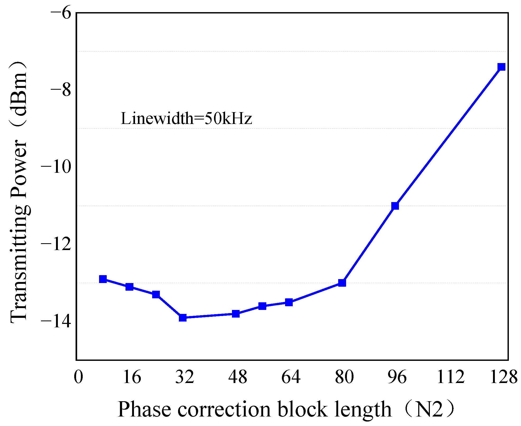
On this basis, we compared the effects of phase-offset-estimation symbol-block length N2 on the receiver sensitivity of the proposed JCSCR in a medium-turbulence channel. In this simulation, FOE symbol-block length N1 = 512 and the laser linewidth was 50 kHz. In this paper, we used the 7% overhead forward-error-correction (FEC) hard judgment threshold (3.8 × 10⁻³) as the system bit-error-rate (BER) performance judgment value. Figure 6 shows that for the same laser linewidth, when the BER reached 3.8 × 10⁻³, the effect of suppressing Gaussian noise became obvious with the increase in phase-offset-estimation symbol-block length N2. The required transmitting power gradually decreased, and the receiver sensitivity gradually increased. When block length N2 increased to a certain level, the performance of the receiver system deteriorated sharply. This is because the long average length of N2 meant that a large number of symbol samples shared the same estimated phase, so the phase estimation accuracy of each sample decreased. Considering various factors such as noise tolerance, carrier phase tracking, and algorithm complexity [13,26], we consider N2 = 32 the optimal average length for this simulation system.
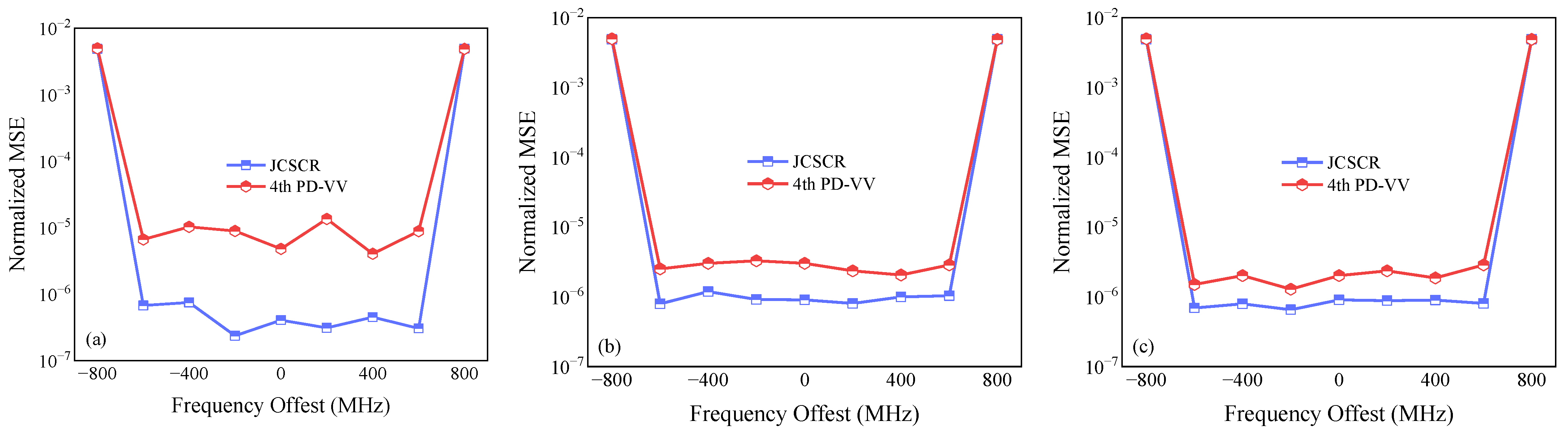
Figure 7 shows the normalized MSEs of the proposed JCSCR and the 4th-PD-VV method when the system was set to different frequency offsets under different atmospheric turbulence states. The symbol-block length of frequency-offset estimation N1 was set to 512 for both algorithms. The transmitting power values of the strong-turbulence, medium-turbulence, and weak-turbulence states were −16 dBm, −18 dBm, and −20.5 dBm, respectively. As shown in Figure 7, the FOE value of the proposed scheme was closer to the actual frequency offset value, with a lower normalized MSE. As the turbulence state enhanced, the proposed scheme was more advantageous. Therefore, the frequency offset estimation accuracy of the proposed JCSCR was significantly better than that of the 4th-PD-VV algorithm.
Figure 8 shows the effect of transmitting power versus BER for the proposed JCSCR and the traditional 4th-PD-VV scheme for different laser linewidths in different atmospheric turbulence channels. The simulation system set the FO to 300 MHz. The lengths of the estimated symbol blocks, N1 and N2, were set to 512 and 32, respectively. As shown in Figure 8, the BERs of both algorithms gradually increased with increases in laser linewidth. However, the JCSCR with a larger linewidth still outperformed the 4th-PD-VV scheme with a smaller laser linewidth under medium turbulence and strong turbulence. With a BER of 3.8 × 10⁻³ and a laser linewidth of 50 kHz, the JCSCR required less transmitting power, and the receiver sensitivity was improved by 3.6 dB, 2.2 dB, and 1.2 dB for the strong turbulence, medium turbulence, and weak turbulence, respectively.
4. Experimental Setup and Results
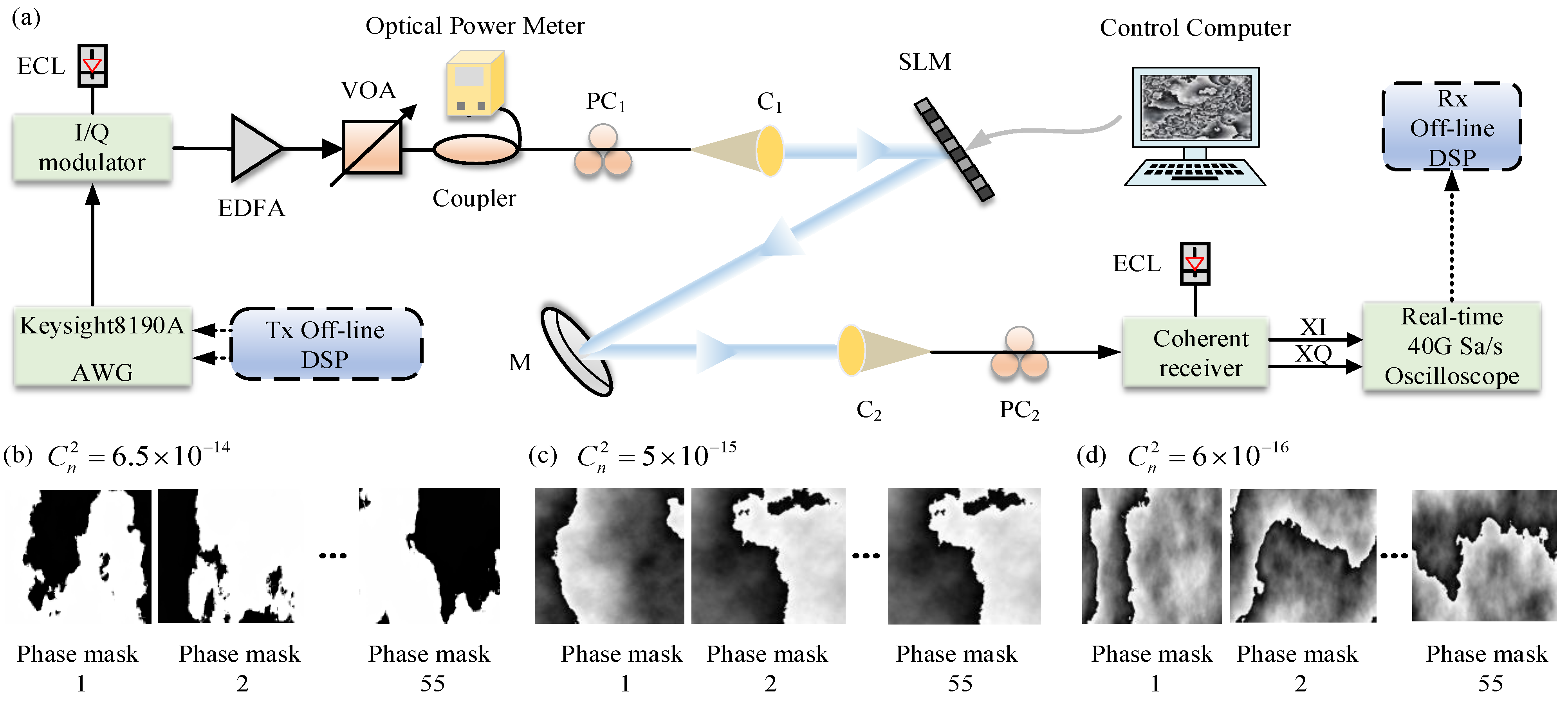
As shown in Figure 9a, the hardware of the 10 Gbps QPSK CFSO communication experimental system consisted of three main components: an optical transmitter, an atmospheric channel transmission link, and an optical receiver front-end. A PLUTO-2 phase-type spatial light modulator (SLM) manufactured by HOLOEYE was used in this experiment to simulate the atmospheric turbulence channel, which had a resolution of 1920 × 1080 pixels [27,28]. The PLUTO-2 SLM was converted from grayscale to phase level, which was reflected in the wavefront phase of light, and thus simulated the atmospheric turbulence effect. Since current commercially available SLMs are sensitive to polarization, polarization multiplexing was difficult to implement in our experiments. However, polarization impairments caused by atmospheric turbulence are rather small and can generally be compensated for through channel equalization, and the proposed scheme gain was independent of polarization. The control computer in this experiment was connected to the SLM via a drive circuit. The control computer could generate the grayscale map corresponding to the set refractive index structure constant of the atmosphere, , and load the grayscale map onto the liquid crystal (LC) display of the SLM. In this experiment, 55 random phase masks were generated and converted into corresponding grayscale maps based on the atmospheric refractive index structure constants (6.5 10−14 , 5 10−15 , and 6 10−16 , respectively) corresponding to strong, medium, and weak turbulence, as shown in Figure 9b–d.
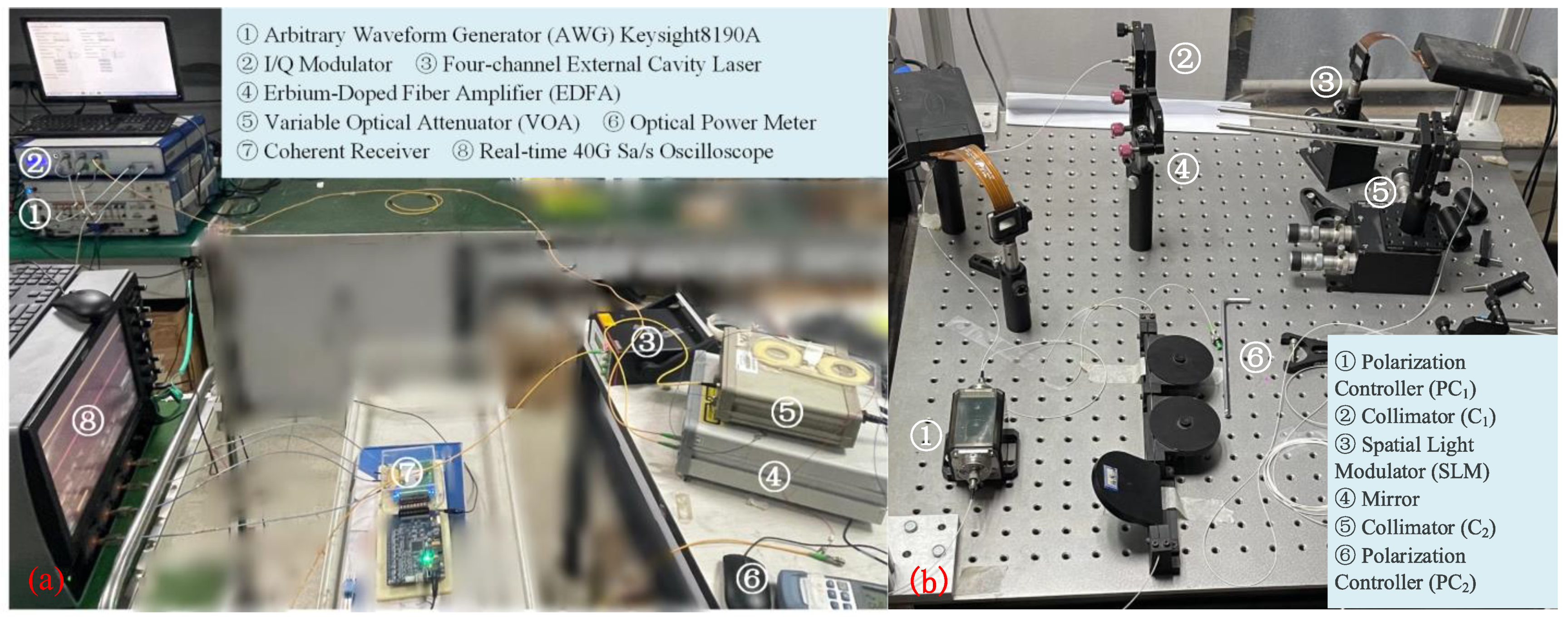
The actual laboratory system scenario diagram is shown in Figure 10. The same DSP code as in the simulation was used to generate the data source at the front end of the optical transmitter. The I and Q signals corresponding to the real and imaginary parts, respectively, were sent to the high-speed arbitrary waveform generator, AWG8190A, with a maximum sampling rate of 12 GSa/s to generate baseband electrical signals. The up-light modulation of the signal was completed with the IQ modulator. A laser with a measurement linewidth of 50 kHz was integrated into the IQ modulator. The output signal light from the modulator was emitted through the telescope into free space. The light-transmitting power was controlled via adjusting the output power of the VOA to vary within a certain range.
After encountering polarization controller PC1 and collimator C1, the signal beam was propagated in free space with the same polarization direction as the function direction of the SLM. The signal beam reached the receiver side after being reflected by the SLM and mirror M, and passed through collimator C2. At the receiver side, polarization PC2 controlling was performed at first. Then, the signal light was fed into a standard single-mode fiber (SSMF), which was subsequently fed into a coherent receiver and oscilloscope for subsequent storage and data processing. The LO laser operated at a wavelength of 193.400 THz and a linewidth of 50 kHz. The FO between the transmitting laser and the LO laser was approximately 300 MHz. The laser beam wavelength was 1550 nm. Collimators C1–C2 were identical and had a focal length of 11.29 mm. The entire indoor transmission link distance was 900 mm. According to the Fresnel scaling theory, this experimental setup can be equated to an outdoor long-distance experiment [29]. In addition, the clock sources of the AWG and the oscilloscope were synchronized in this experiment.
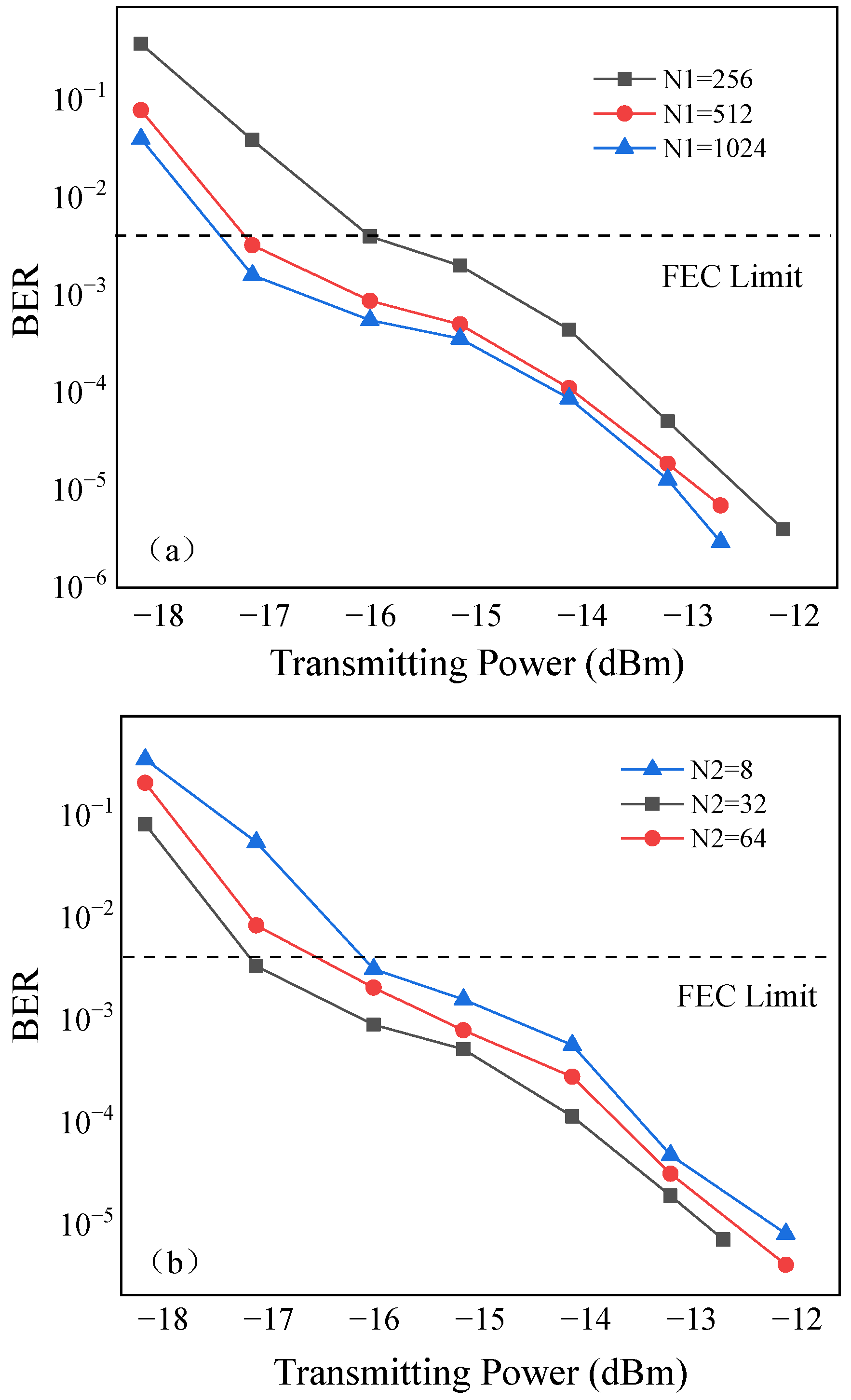
Figure 11a shows FOE symbol-block length N1 versus the BER curve of the proposed JCSCR under the 10 Gbps QPSK CFSO communication experimental system. Experiments showed that the BER performance of the algorithm decreased with decreases in symbol block N1 and it had a low BER at N1 = 512 for the medium-turbulence channel. Based on the experimental results, 512 symbols were selected as the block length of the proposed scheme for the FOE. On this basis, Figure 11b shows the curves of the proposed scheme for phase-offset-estimation symbol-block length N2 versus the BER for the case of N1 = 512. As shown in the figure, the system had a lower BER and better noise immunity than the other values when N2 was 32. Therefore, N2 = 32 was used as the phase offset estimation block length in this experiment.
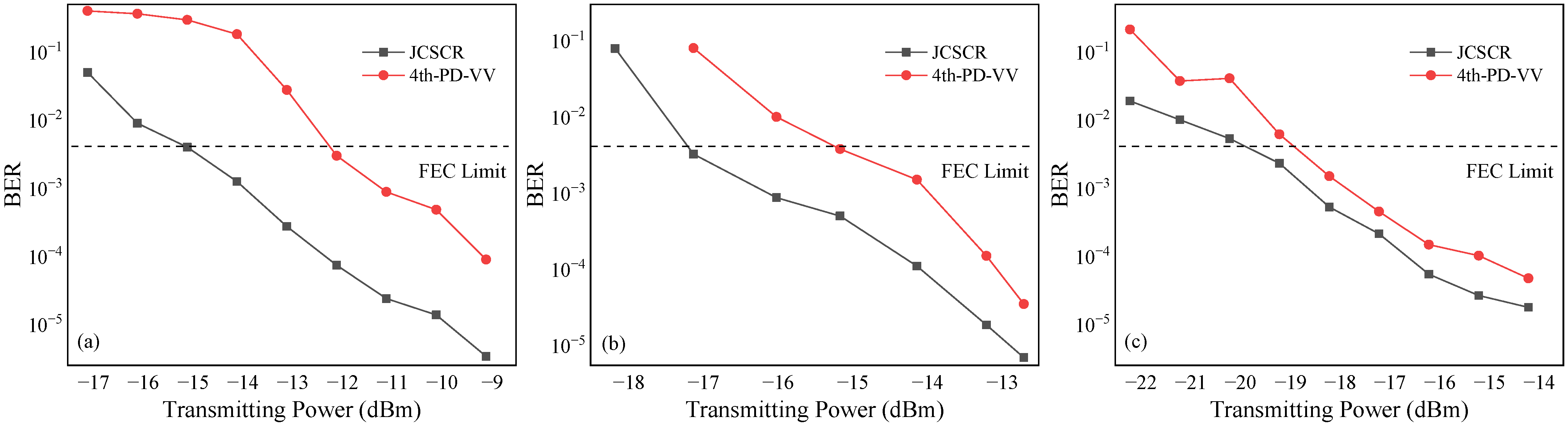
To visually compare the performance of the proposed JCSCR with the traditional 4th-PD-VV carrier scheme, when N1 = 512 and N2 = 32, we compared the transmitting power versus the BER for strong-, medium-, and weak-turbulence channels, respectively. Figure 12 shows that the proposed algorithm exhibited a better performance than the 4th-PD-VV scheme in BER limit (3.8 × 10⁻³), improving receiver sensitivity by 3.3 dB, 2.1 dB, and 1.1 dB in the strong-, medium-, and weak-turbulence states, respectively. In addition, there was a difference of nearly 3 dB between the experimental and simulated results, owing to the lack of polarization multiplexing in this experiment. It can thus be seen that the conclusions drawn from the experiments and simulations are in agreement.
5. Complexity Analysis
In this section, we will analyze the computational complexity of the proposed JCSCR and the 4th-PD-VV algorithm in the QPSK modulation format. The real multipliers and real adders required for the two whole schemes when the length of the participating frequency-offset-estimation symbol block and the phase-offset-estimation symbol block were N1 and N2, respectively, are shown in Table 1. The complexity of the 4th-PD-VV scheme using fourth-power operations to remove the modulation-phase operation increased considerably with increases in block length. Additionally, the M power operation requires more real multipliers when the number of powers increases [30]. In contrast, the JCSCR algorithm signal-preprocessing stage avoids the resource-consuming fourth-power operation. For complex signals of length N1, the signal-preprocessing stage requires only 11N1 real adders to perform the modulation-phase-removal operation. The JCSCR only requires preprocessing to remove the modulated phase of the signal and subsequent joint compensation operation, which helps to further reduce the complexity of the overall scheme. In field programmable gate array (FPGA),multiplication is implemented through multiple shift operations and multiple addition operations, and the complexity of multiplier implementation is much greater than that of adders. Therefore, the complexity of a scheme is mainly discerned through the number of multipliers. Based on Table 1, the number of multipliers required in the operation of the proposed JCSCR was less than of that for the 4th-PD-VV algorithm, which is more favorable for implementing the algorithm in FPGAs.
6. Discussion
In summary, we propose a low-complexity JCSCR that simplifies removal of modulation-phase-repetition operations and jointly compensates for estimation errors to reduce the system complexity and improve the transmission capability of the CFSO communication transmission system. With the same atmospheric turbulence states and estimated symbol blocks, simulations and experiments verified that our proposed scheme achieves lower complexity, higher noise tolerance capability, and higher receiver sensitivity than does the traditional 4th-PD-VV scheme under QPSK-modulated signals. In addition, the information capacity of the system can be further enhanced using high-order QAM-format signals. CFSO systems with high-order QAM-format signals are also in urgent need of low-complexity, efficient carrier recovery schemes. Studying how to optimize the existing QAM carrier recovery algorithm and demonstrate its feasibility in CFSO communication systems is what we want to work on in the future.
7. Conclusions
In this article, a low-complexity JCSCR was proposed and introduced into the CFSO communication system. The proposed algorithm only used addition and subtraction of real absolute values in the preprocessing stage to remove the signal modulation phase, reducing system complexity while avoiding the appearance of additional noise generated by cross-terms. In addition, a joint compensation error was proposed for use in the carrier-compensation stage to further reduce the complexity of the overall algorithm scheme. The number of multipliers required in the operation of the JCSCR in the complexity analysis was less than of the 4th-PD-VV. The results of the simulation demonstrated that the proposed algorithm can achieve high-precision carrier recovery with much lower complexity, even with large laser linewidths. Moreover, the FOE accuracy of the proposed scheme was improved by one order of magnitude for the same symbol-block length of FOE under strong turbulence. Compared with the traditional 4th-PD-VV scheme, the transmitting power required at BER = 3.8 × 10⁻³ was reduced by 3.6 dB, 2.2 dB, and 1.2 dB for the strong-, medium-, and weak-turbulence states, respectively. The experimental results further verified the robustness and feasibility of the proposed scheme in the QPSK CFSO system. In addition, improvements of receiver sensitivity were also experimentally validated. The proposed scheme can significantly improve free-space link-transmission capacity and ensure communication reliability, which is expected to provide technical support for a large amount of high-speed satellite observation data transmission in real time and satisfy the development demand for a next-generation space optical communication system with a large capacity and high speed.
Author Contributions
Conceptualization, X.T.; methodology, X.T. and L.W.; software, X.T. and Y.L.; writing—original draft preparation, X.T.; writing—review and editing, X.T., S.C. and W.Z.; project administration, L.W. and Z.Z.; funding acquisition, Z.Z. All authors have read and agreed to the published version of the manuscript.
Funding
This work was supported by the National Natural Science Foundation of China (General Program) (Grant No. 62271084) and the Joint Funds of the National Natural Science Foundation of China (Grant No. U22B2009).
Institutional Review Board Statement
Not applicable.
Informed Consent Statement
Not applicable.
Data Availability Statement
The data presented in this study are available upon reasonable request from the corresponding authors.
Conflicts of Interest
The authors declare no conflict of interest.
References
- Kaushal, H.; Jain, K.; Kar, S. Free Space Optical Communication; Springer: Mumbai, India, 2017. [Google Scholar]
- Guiomar, F.P.; Fernandes, M.A.; Nascimento, J.L.; Rodrigues, V.; Monteiro, P.P. Coherent Free-Space Optical Communications: Opportunities and Challenges. J. Light. Technol. 2022, 40, 3173–3186. [Google Scholar] [CrossRef]
- Niu, M.; Song, X.; Cheng, J.; Holzman, J.F. Performance analysis of coherent wireless optical communications with atmospheric turbulence. Opt. Express 2012, 20, 6515–6520. [Google Scholar] [CrossRef] [PubMed]
- Kaushal, H.; Kaddoum, G. Optical communication in space: Challenges and mitigation techniques. IEEE Commun. Surv. Tutor. 2017, 19, 57–96. [Google Scholar] [CrossRef] [Green Version]
- Kovalik, J.; Biswas, A.; Wilson, K. Data products for the OCTL to OICETS optical link experiment. Int. Soc. Opt. Eng. 2010, 7587, 75870C. [Google Scholar]
- Siao, L.; Hao, H. Enabling technology in high-baud-rate coherent optical communication systems. IEEE Access 2020, 8, 111318–111329. [Google Scholar] [CrossRef]
- Kumar, P. Comparative analysis of BER performance for direct detection and coherent detection FSO communication systems. In Proceedings of the IEEE Conference on Communication Systems and Network Technologies, Gwalior, India, 4–6 April 2015; pp. 369–374. [Google Scholar]
- Perlot, N. Turbulence-induced fading probability in coherent optical communication through the atmosphere. Appl. Opt. 2007, 46, 7218–7226. [Google Scholar] [CrossRef] [Green Version]
- Zhou, H.; Xie, W.; Zhang, L.; Bai, Y.; Wei, W.; Dong, Y. Performance analysis of FSO coherent BPSK systems over rician turbulence channel with pointing errors. Opt. Exp. 2019, 27, 27062–27075. [Google Scholar] [CrossRef]
- Meng, W.; Huiying, Z.; Baiquan, C. PS-QPSK modulation system analysis in FSO. Res. Explor. Lab. 2017, 36, 146–183. [Google Scholar]
- Leven, A.; Kaneda, N.; Koc, U.V. Frequency estimation in intradyne reception. IEEE Photonics Technol. Lett. 2006, 19, 366–368. [Google Scholar] [CrossRef]
- Viterbi, A. Nonlinear estimation of PSK-modulated carrier phase with application to burst digital transmission. IEEE Trans. Inf. Theory 1983, 29, 543–551. [Google Scholar] [CrossRef]
- Ly-Gagnon, D.; Tsukamoto, S.; Katoh, K.; Kikuchi, K. Coherent detection of optical quadrature phase-shift keying signals with carrier phase estimation. J. Light. Technol. 2006, 24, 12–21. [Google Scholar] [CrossRef]
- Li, X.; Geng, T.; Ma, S.; Li, Y.; Gao, S.; Wu, Z. Performance improvement of coherent free-space optical communication with quadrature phase-shift keying modulation using digital phase estimation. Appl. Opt. 2017, 56, 4695–4701. [Google Scholar] [CrossRef] [PubMed]
- Han, J.; Li, W.; Yuan, Z.; Zheng, Y.; Hu, Q. A simplified implementation method of Mth-power for frequency offset estimation. IEEE Photonics Technol. Lett. 2016, 28, 1317–1320. [Google Scholar] [CrossRef]
- Han, J.; Li, W.; He, Z.; Hu, Q.; Yu, S. Multiplier-Free Carrier Phase Estimation for Optical Coherent Systems. IEEE Photonics Technol. Lett. 2016, 28, 2168–2171. [Google Scholar] [CrossRef]
- Cao, Y.; Yu, S.; Shen, J.; Gu, W.; Ji, Y. Frequency estimation for optical coherent MPSK system without removing modulated data phase. IEEE Photonics Technol. Lett. 2010, 22, 691–693. [Google Scholar] [CrossRef]
- Fatadin, L.; Ives, D.; Savory, S.J. Laser Linewidth Tolerance for 16-QAM Coherent Optical Systems Using QPSK Partitioning. IEEE Photonics Technol. Lett. 2010, 22, 631–633. [Google Scholar] [CrossRef]
- Zhou, X.; Zhou, Z.; Tian, P.; Yuan, X. Numerical research on partially coherent flat-topped beam propagation through atmospheric turbulence along a slant path. Appl. Opt. 2019, 58, 9443–9454. [Google Scholar] [CrossRef]
- Andrews, L. Laser Beam Scintillation with Applications; SPIE Press: Bellingham, WA, USA, 2001. [Google Scholar]
- Andrews, L. Laser Beam Propagation through Random Media; SPIE Press: Bellingham, WA, USA, 2001. [Google Scholar]
- Chen, H.; Yang, T.; Wang, L.; Chen, X.; Zhang, L.; Zhang, Z. Phase uniformly distributed circular MQAM combined with probabilistic shaping for PM-CO-OFDM systems in satellite-to-ground optical communications. IEEE Photonics J. 2019, 11, 1–10. [Google Scholar] [CrossRef]
- Schmidt, J.D. Numerical Simulation of Optical Wave Propagation with Examples in MATLAB; SPIE: Bellingham, WA, USA, 2010. [Google Scholar]
- Nistazakis, H.E.; Karagianni, E.A.; Tsigopoulos, A.D.; Fafalios, M.E.; Tombras, G.S. Average Capacity of Optical Wireless Communication Systems Over Atmospheric Turbulence Channels. J. Light. Technol. 2009, 27, 974–979. [Google Scholar] [CrossRef]
- Goldfarb, G.; Li, G. BER estimation of QPSK homodyne detection with carrier phase estimation using digital signal processing. Opt. Express 2006, 14, 8043–8053. [Google Scholar] [CrossRef]
- Tsukamoto, S.; Katoh, K.; Kikuchi, K. Coherent demodulation of optical multilevel phase-shift-keying signals using homodyne detection and digital signal processing. IEEE Photonics Technol. Lett. 2006, 18, 1131–1133. [Google Scholar] [CrossRef]
- Zhen, Q.; Djordjevic, I.B. Approaching terabit optical transmission over strong atmospheric turbulence channels. In Proceedings of the 2016 18th International Conference on Transparent Optical Networks (ICTON), Trento, Italy, 10–14 July 2016; pp. 1–5. [Google Scholar] [CrossRef]
- Cai, S.; Zhang, Z.; Hu, Y.; Gong, B.; Chen, X. Demonstration of Turbulence and Pointing Error Resistant for Free-Space to Single-Mode Coupling Using Photonic Lantern. In Proceedings of the 24th OptoElectronics and Communications Conference (OECC) and 2019 International Conference on Photonics in Switching and Computing (PSC), Fukuoka, Japan, 7–11 July 2009. [Google Scholar]
- Rodenburg, B.; Mirhosseini, M.; Malik, M. Simulating thick atmospheric turbulence in the lab with application to orbital angular momentum communication. New J. Phys. 2014, 16, 089501. [Google Scholar] [CrossRef]
- Meiyappan, A.; Kam, P.; Kim, H. On Decision Aided Carrier Phase and Frequency Offset Estimation in Coherent Optical Receivers. J. Light. Technol. 2013, 31, 2055–2069. [Google Scholar] [CrossRef]
Figure 1.
Block diagram of the proposed scheme.

Figure 2.
Block diagram of the signal-preprocessing stage.

Figure 3.
Comparison of the results of the absolute-value operation and the square operation of the (a) cosine functions and the (b) sine functions.
Figure 3.
Comparison of the results of the absolute-value operation and the square operation of the (a) cosine functions and the (b) sine functions.

Figure 4.
Simulation setup for a 10 Gbps QPSK CFSO transmission system.

Figure 5.
Normalized MSE as a function of the transmitting power for different N1 values.

Figure 6.
Transmitting power as a function of different N2 values.

Figure 7.
Normalized MSEs as functions of different frequency offsets: (a) 6.5 10−14 , (b) 5 10−15 , and (c) 6 10−16 .
Figure 7.
Normalized MSEs as functions of different frequency offsets: (a) 6.5 10−14 , (b) 5 10−15 , and (c) 6 10−16 .

Figure 8.
BER as a function of the transmitting power at different linewidths: (a) 6.5 10−14 , (b) 5 10−15 , and (c) 6 10−16 .
Figure 8.
BER as a function of the transmitting power at different linewidths: (a) 6.5 10−14 , (b) 5 10−15 , and (c) 6 10−16 .

Figure 9.
Experimental setup for a 10 Gbps QPSK CFSO transmission system. ECL: external cavity laser; PC: polarization controller; C: collimator; M: mirror; SLM: space light modulator. (a) QPSK CFSO communication experiment system diagram. (b) Grayscale map of strong-turbulence channel. (c) Grayscale map of medium-turbulence channel. (d) Grayscale map of weak-turbulence channel.

Figure 10.
Laboratory system scenario diagram: (a) transmitter, receiver, and (b) atmospheric-turbulence-simulation optical-experiment platform.
Figure 10.
Laboratory system scenario diagram: (a) transmitter, receiver, and (b) atmospheric-turbulence-simulation optical-experiment platform.

Figure 11.
Experimentally measured BER as a function of transmitting power for different values of N1/N2.: (a) different N1 values, (b) different N1 values.
Figure 11.
Experimentally measured BER as a function of transmitting power for different values of N1/N2.: (a) different N1 values, (b) different N1 values.

Figure 12.
Experimentally measured BER as a function of transmitting power for the proposed algorithm and the 4th-PD-VV algorithm: (a) 6.5 10−14 , (b) 5 10−15 , and (c) 6 10−16 .
Figure 12.
Experimentally measured BER as a function of transmitting power for the proposed algorithm and the 4th-PD-VV algorithm: (a) 6.5 10−14 , (b) 5 10−15 , and (c) 6 10−16 .


Table 1.
Computational complexity of different schemes.
| Scheme | Real Multiplication | Real Addition |
|---|---|---|
| 4th-PD-VV | 12N1 + 8N2 + 6 | 8N1 + 6N2-4 |
| JCSCR | 4N1 + 4 | 15N1 + 2N2-3 |
Disclaimer/Publisher’s Note: The statements, opinions and data contained in all publications are solely those of the individual author(s) and contributor(s) and not of MDPI and/or the editor(s). MDPI and/or the editor(s) disclaim responsibility for any injury to people or property resulting from any ideas, methods, instructions or products referred to in the content. |
© 2023 by the authors. Licensee MDPI, Basel, Switzerland. This article is an open access article distributed under the terms and conditions of the Creative Commons Attribution (CC BY) license (https://creativecommons.org/licenses/by/4.0/).
Share and Cite
MDPI and ACS Style
Tang, X.; Wang, L.; Zhang, W.; Cai, S.; Li, Y.; Zhang, Z. A Low-Complexity Joint Compensation Scheme of Carrier Recovery for Coherent Free-Space Optical Communication. Photonics 2023, 10, 389. https://doi.org/10.3390/photonics10040389
AMA Style
Tang X, Wang L, Zhang W, Cai S, Li Y, Zhang Z. A Low-Complexity Joint Compensation Scheme of Carrier Recovery for Coherent Free-Space Optical Communication. Photonics. 2023; 10(4):389. https://doi.org/10.3390/photonics10040389
Chicago/Turabian StyleTang, Xinyu, Liqian Wang, Wei Zhang, Shanyong Cai, Yuemei Li, and Zhiguo Zhang. 2023. "A Low-Complexity Joint Compensation Scheme of Carrier Recovery for Coherent Free-Space Optical Communication" Photonics 10, no. 4: 389. https://doi.org/10.3390/photonics10040389
Note that from the first issue of 2016, this journal uses article numbers instead of page numbers. See further details here.