Design of Full Stokes Vector Polarimetry Based on Metasurfaces for Wide-Angle Incident Light
by

Songjie Liu
1, 
Zejun Zhang
1,2,*,
Jingxuan Cheng
1,
Xiyin Wang
1,
Shixiao Sun
1 and
Jing Xu
1,2,3 1
Optical Communications Laboratory, Ocean College, Zhejiang University, Zhoushan 316021, China
2
Key Laboratory of Ocean Observation-Imaging Testbed of Zhejiang Province, Ocean College, Zhejiang University, Zhoushan 316021, China
3
Hainan Institute of Zhejiang University, Sanya 572000, China
*
Author to whom correspondence should be addressed.
Photonics 2023, 10(4), 382; https://doi.org/10.3390/photonics10040382
Submission received: 1 March 2023
/
Revised: 27 March 2023
/
Accepted: 28 March 2023
/
Published: 30 March 2023
(This article belongs to the Special Issue Metasurface Diffraction and Polarization Optics)
Abstract
:Polarization measurement plays an important role in optical detection, communication, and imaging systems. Compact polarimetry with a wide angle of incident light will break the restrictions of the limited incident angle and improve its practicality. In this paper, a full Stokes vector polarimetry with a wide incident angle of ±20°, based on a two-dimensional metasurface, is proposed. According to the simulation results, the maximum measurement error of the Stokes vector at 20° oblique incidence is 0.09. The light transmittance of the proposed structure is higher than 83%. Moreover, the tilt angle of the incident light can be determined with a calculation error lower than 0.5°, according to the focusing position of the transmitted light on the focal plane. The operating wavelength of the proposed polarimetry is set to 530 nm of green light, which makes it a potential application in visible light communication and underwater optical systems.
1. Introduction
Polarization is an inherent property of light that can provide more information than light intensity, such as surface topography, shape and shading of a target [1]. Therefore, during the 1980s, it played an important role in the development of polarization navigation [1], polarization imaging [2], atmospheric environment detection [3], and optical fiber communication technologies [4]. Since the Stokes vector can be obtained by measuring the light intensities of different polarization components, it is generally used to represent the polarized information of light. At present, high-precision Stokes vector measurement technology plays an indispensable role in the field of microstructure detection, such as cancer cell screening [5] and underwater microplastic detection [6]. In addition, due to the different depolarization properties of materials, Stokes vector detection of the light reflected by a target can enable applications such as camouflaged target detection [7], material recognition [8], and optical characteristic detection [9]. Traditional polarization detection methods can be divided into two categories: time-division measurement [10] and simultaneous measurement [11]. Time-division measurement is used to detect polarization states by means of rotating polarizers and wave plates, meaning it is only suitable for static scenes due to its long acquisition time. Simultaneous detection systems split the incident light and detect the corresponding polarization component simultaneously. These systems can be further subdivided into division of amplitude detection [12], division of aperture detection [13], and division of focal plane detection [14] systems. However, the characteristics of complex optical paths and the large volume of these systems are inconsistent with the development of miniaturization and integrated optical systems.
On account of their small size, compact alignment, and easy integration [15,16], the application of two-dimensional metasurfaces provides a possibility for solving the problems above. Metasurfaces can be used to control the amplitude [17], phase [18], and polarization state [19] of electromagnetic fields, and have promoted the development of metasurfaces in the field of optics. At present, various functions, such as beam deflection [20], beam convergence [21], holography [22], wavefront shaping [23], splitting [24], and absorption [25] have been realized by using metasurfaces. In addition, the metasurface material has a negative refractive index [20], meaning it can easily focus the incident light at a large angle. This feature provides a solution to the problem of limited incident angles of a polarimetry. According to the material, metasurface-based polarimetries are generally divided into two types, i.e., the plasmonic type [26] and dielectric type [27]. In 2015, Pors et al. proposed a plasmonic metasurface-based polarimetry to achieve the full Stokes vector measurement without the use of additional polarization devices [26]. In contrast, dielectric metasurfaces attract extensive attention due to their improved efficiency without the inherent absorption of metallic materials. In 2018, Guo et al. proposed a dielectric metasurface-based polarimetry to achieve an overall energy efficiency improvement in the visible light bandwidth [27]. By utilizing the double-phase modulation method, the polarization detection efficiency has been further improved. In the same year, Arbabi et al. proposed a full Stokes polarimetry for infrared light and realized the physical verification of the polarization imaging function [28]. However, these polarimetries still require the incident light to be perpendicular to the metasurface. In 2020, Zhang et al. realized the first polarimetry with a wide incident angle in terahertz bandwidth [29]. The metasurface unit structure was proposed with six parts, which focused multiple orthogonal polarization components on the focal plan, but the transmittance efficiency of the structure can be further improved.
In this paper, a full Stokes parameter measurement is proposed, based on gallium nitride (GaN) metasurface in visible light band. Considering underwater polarization imaging and target recognition techniques based on polarization detection, the central operation wavelength is set to 530 nm of green light, which has a relatively low absorption loss in underwater environments [30]. Combining the double-phase modulation [27] and geometric phase modulation [28] methods, our proposed metasurface consists of three subarrays, which can efficiently split and focus the orthonormal polarization components, as well as measure the tilt angle of incident light.
2. Proposed Metasurface-Based Polarimetry
The polarization state of a light wave can be described by the Stokes vector, and the four parameters used can be further represented by the light intensity of the horizontal and vertical linear polarization (i.e., and ), the ±45° linear polarization (i.e., and ), and the left and right circular polarization (i.e., and ) components. The Stokes vector is given as follows.
For an oblique incident light, it is necessary to find out the relationship between the incident light intensity and the transmitted light intensity .
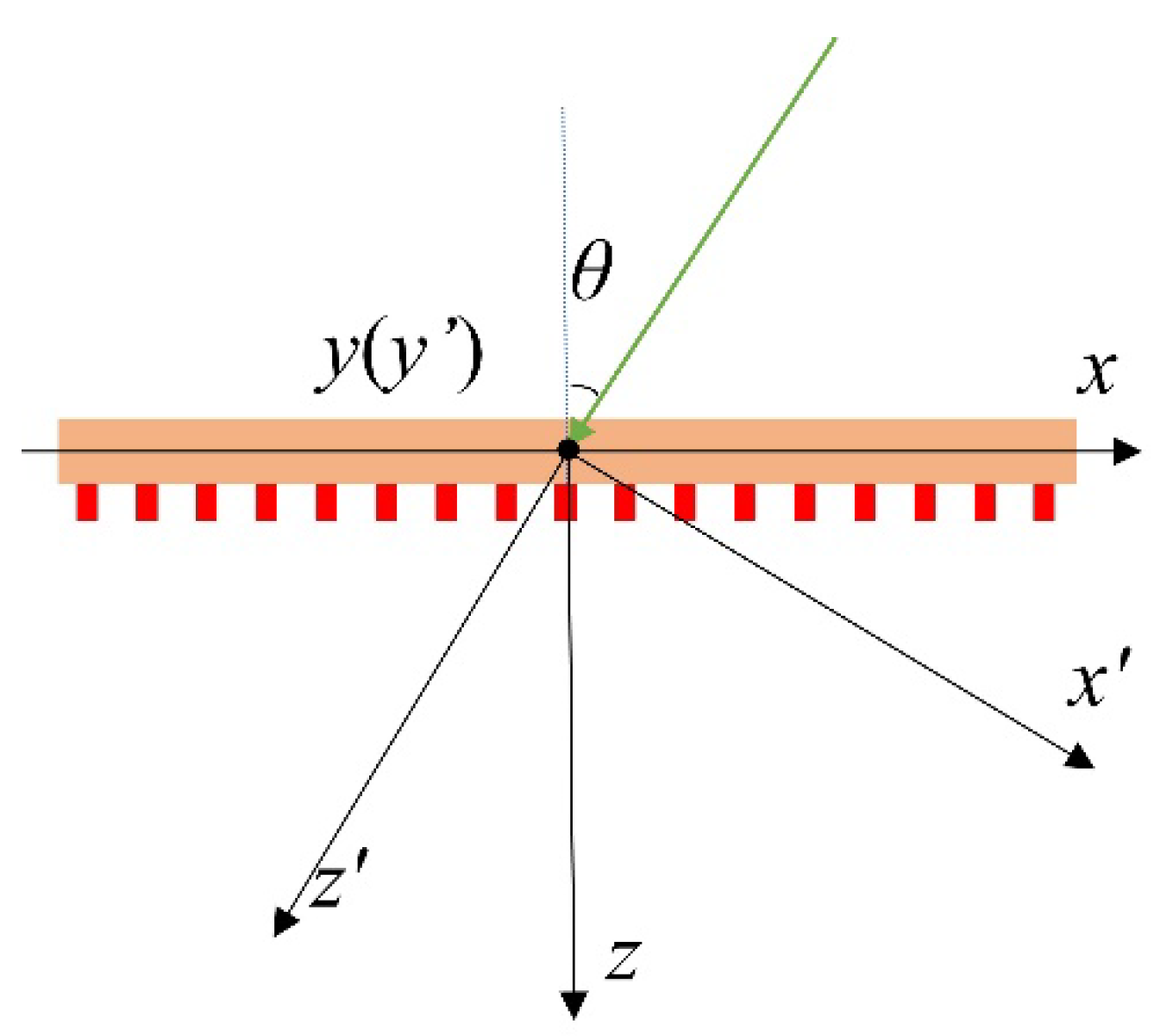
For the convenience of representation, two Cartesian coordinate systems, xyz and x’y’z’, are established, as shown in Figure 1. The y-axis and y’-axis are in the same direction, the z-axis and z’-axis correspond to the normal direction of the metasurface and the direction of incident light, respectively. The transformation of a point in the x’y’z’ coordinate system to the xyz coordinate system can be represented by using the rotation matrix ,
where is the tilt angle of incident light. According to the coordinate transformation, for an oblique incident light, the relationship between the measured light intensities and the incident light polarization component is
Therefore, the relationship between the Stokes vector of incident light and the measured light intensity can be illustrated as follows.
For the transmitted light on the focal plane, the phase distribution can be expressed by [29]
where is the wave number in a vacuum, is the focal length, and is the focus position in the case of normal incidents.
When the tilt angle of incident light is , taking the x-direction as an example, the phase carried by the output light should be
where is the phase shift introduced by the oblique incidence. Since it is the last term independent of r, it can be considered as a constant for each fixed angle . Compared with normal incidence, the incident light with tilt angle is laterally shifted along the x-direction by an offset of . Therefore, the tilt angle can be determined by measuring the offset of the focal spot along the x-direction. Then, the Stokes vector can be obtained through the incident angle and the transmitted light intensity for each polarization component.
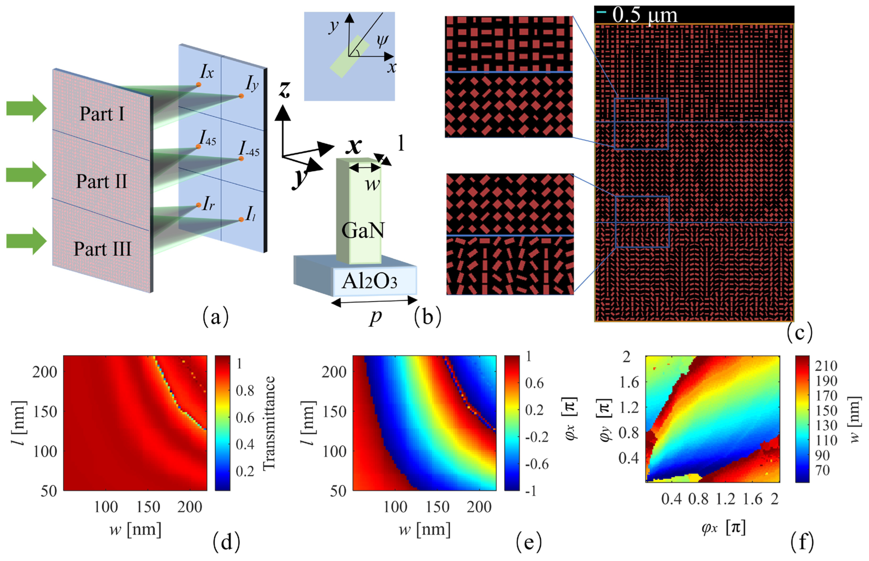
In this paper, the metasurface-based polarimetry is designed for green light waves and the operation wavelength is set to 530 nm. Each unit cell for the metasurface includes a GaN nanopillar and an Al2O3 substrate, as shown in Figure 2b. During the modeling process, the thickness of the substrate is set to 300 nm [27], the height of the nanopillar is set to 800 nm, and the center of the nanopillar is located on the center of substrate. The entire design region contains 20 × 40 × 3 unit lattice structures. The length, l, width, w, and rotation angle, , of the nanopillar in each unit lattice determine the phase shift of the transmitted light.
The polarimetry consists of three subarrays (corresponding to Parts I, II, and III) that decompose the incident light into three groups of orthogonal bases: x-LP and y-LP (i.e., 0° and 90° linearly polarized light), 45°-LP and 135°-LP (i.e., 45° and 135° linearly polarized light), and RCP and LCP (i.e., right and left circularly polarized light), as shown in Figure 2a. The transmitted polarized lights are focused on the focal plane to complete the full Stokes parameter measurement. Figure 2c is a top view of the structure, in which the blue line is the 0.5 micron scale. Different subarrays have different nanopillar arrangements according to the phase of the transmitted light. Each subarray contains 20 × 40 periodic unit cells with a size of 5.2 µm × 10.4 µm, the focal length is set to 6 μm, and the lattice pitch for each unit is 260 nm. The geometric distribution of each nanopillar is determined by the modulation phase function of the metasurface.
The variations in transmittance and x-polarization phase shifts of the incident light with different nanopillar length and width are simulated based on the finite difference time domain (FDTD) method, as shown in Figure 2d,e. Here, an x-polarized light with a wavelength of 530 nm is used to perpendicularly incident on the metasurface and the x, y boundary conditions are set as periodic boundaries. The modulating phase shift of the transmitted light can almost completely cover the entire 2π, which ensures the random phase modulation of the transmitted light. The high transmittance also ensures the efficient use of incident energy. Additionally, the variations in the y-polarization phase shifts with different nanopillar sizes is in a transposed relationship with the x-polarization, which is not shown in detail here [31].
According to the phase shifts of x- and y-polarization, the variation in the nanopillar geometric parameters with different phase values can be obtained. The relationship between the width, w, with and is shown in Figure 2f. The matrix of l is the transposed matrix of w, which is not shown in detail here. In our design process, the phase distribution of the transmitted light is determined according to its focus position and then the size of each nanopillar is determined by the different phase variations of and . For the structure of Part I, the phases of the transmitted light for the x- and y-polarization components can be designed independently, and there is always a rectangular GaN nanopillar that can simultaneously satisfy the needs of the two orthogonal polarization phases. Moreover, the transmittance is close to 1, which indicates that the structure has a high energy utilization efficiency. For the structure of ±45° linear polarizations (Part II), the phase control can be easily achieved by rotating the nanopillars 45° in Part I. In addition, for the structure of circular polarizations (Part III), the principle of the Pancharatnam–Berry phase, which is the phase of the output orthogonally polarized light, is twice the rotation angle of the nanopillar, and can be used to design the transmitted light phase [27]. The appropriate nanopillars are selected by conditions of transmittance and phase difference. Then, the phase of the transmitted orthogonally polarized light is adjusted through the rotation angle of the nanocolumns. Due to the periodic phase modulation of the metasurface structure, there are theoretically infinite sets of structure combinations; the structure parameters used in this paper are shown in Table S1 (Supplementary Materials).
3. Results and Discussion
3.1. Stokes Vector Detection for Vertical Incident Light
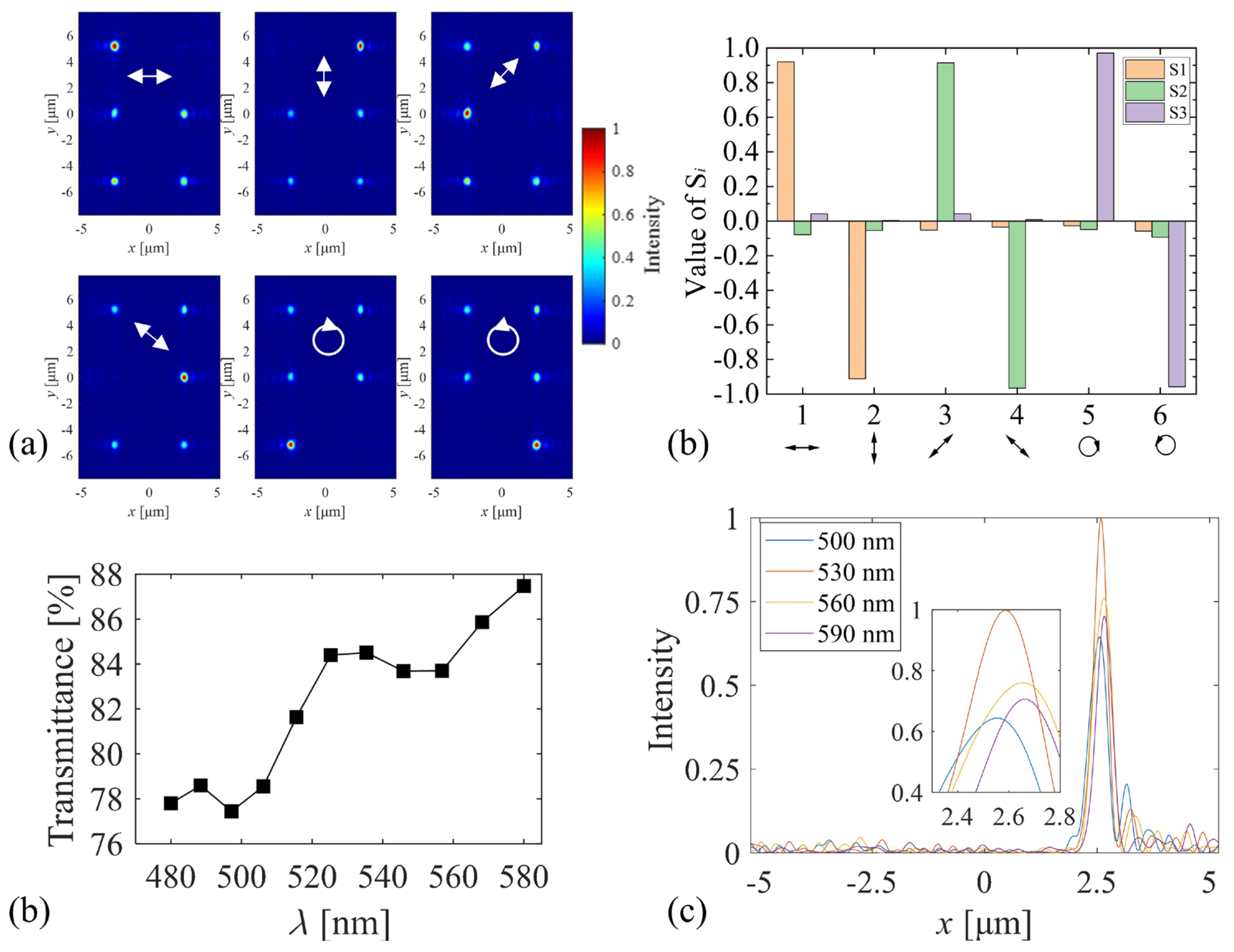
In order to verify the effectiveness of the proposed polarimetry, the FDTD method is used to simulate light propagation, and the intensity distributions on the focal plane for six basic polarized lights (i.e., x-LP, y-LP, 45°-LP, 135°-LP, RCP, and LCP) are obtained, as shown in Figure 3a. The last three terms of the normalized Stokes parameters for the selected six polarization states are, respectively, [1, 0, 0]T, [−1, 0, 0]T, [0, 1, 0]T, [0, −1, 0]T, [0, 0, 1]T, and [0, 0, −1]T. The Full Width at Half Maximum (FWHM) method is used to determine the effective light spot area. The light intensity through the spot area in each Part is measured and normalized to calculate the Stokes parameters. The calculated Stokes parameters are shown in Figure 3b. The maximum error is less than 0.09, which is close to the result of article [29,32]. Notably, the maximum error is random, rather than fixed in a certain polarization state. The main reason for this is considered to be the approximate representation of the focus phase distribution, shown in Equation (5). Moreover, in the optical field simulation process, due to the inherent errors of the computer, these will lead to random differences in the optical field distribution. These results prove that our proposed structure has the ability to detect the polarization state of vertically incident light.
The wavelength dependence of the structure has also been discussed under the normal incident scenario. The transmittance is calculated according to the intensity ratio of transmitted light to the incident light. At the wavelength of 530 nm, the average transmittance of the metasurface is 83.9%. To evaluate the wavelength dependence of the transmittance, the simulation wavelength varied in the range of 480~580 nm; the calculated transmittance is shown in Figure 3c. The trend in the transmittance curve is consistent with the data in [33]. Moreover, as the wavelength varies, the position of the focal spot shifts along the x-direction. Figure 3d shows the y-polarized focal light intensity of Part I with wavelengths of 500, 530, 560, and 590 nm, respectively. The inset is the enlarged view of the peak value area. The intensities reach their maximum value at 530 nm and decrease with the wavelength variation. This is because different wavelengths lead to different focal lengths, and the focusing energy decreases on the focal plane with . Moreover, it was found that as the wavelength increases, the spot position gradually moves linearly to the right side.
3.2. Stokes Vector Detection for Oblique Incident Light
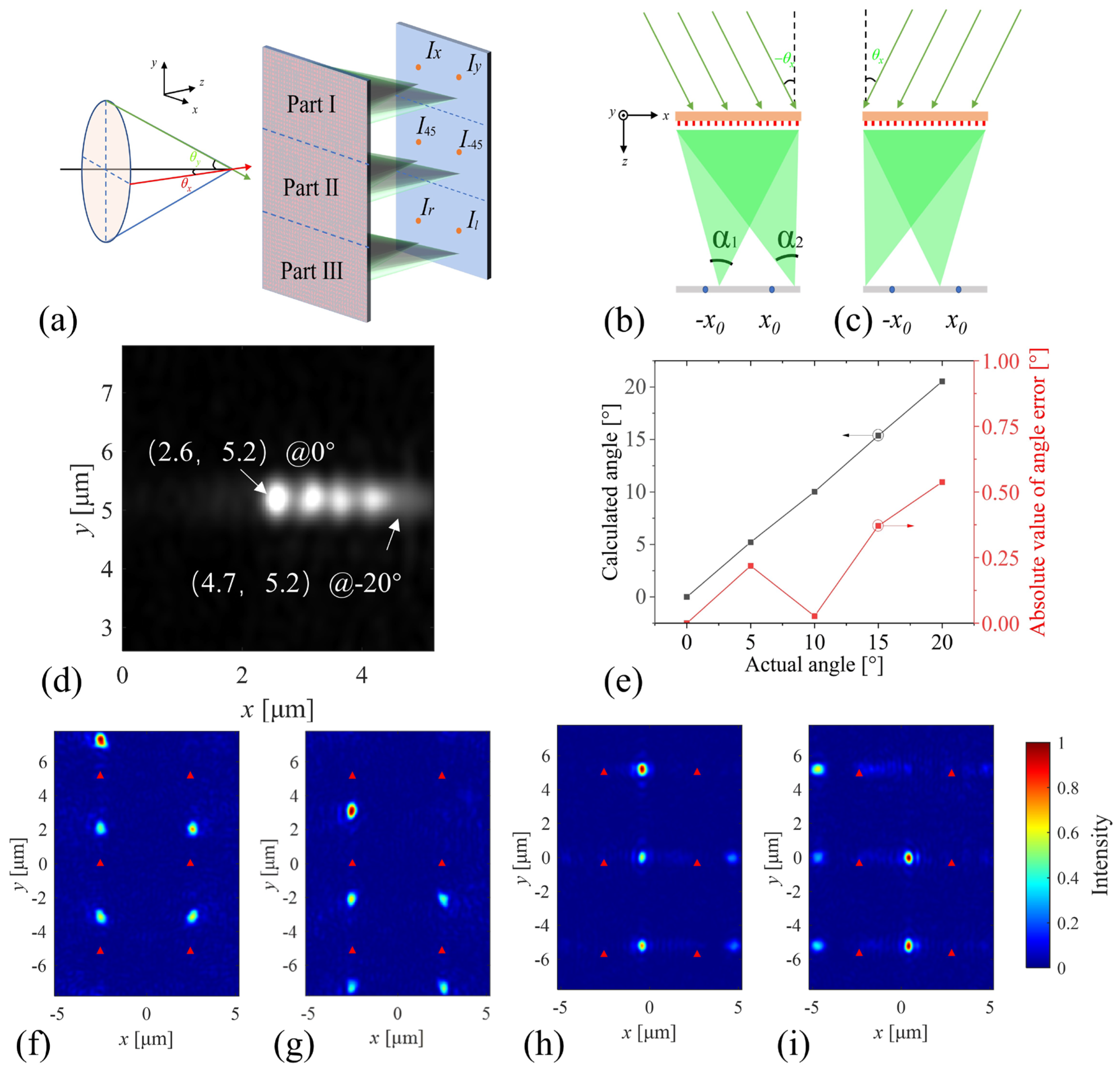
Having discussed the measurement results of normal incidence, the polarization detection in the case of oblique incidence will now be shown. Figure 4a is a schematic diagram of an oblique incidence scenario; an arbitrary incident direction can be decomposed into oblique incident components along the x- and y-axis, and the focus positions also vary from the positions under the normal incident scenario (shown as the red dots). Figure 4b,c are schematic diagrams of the tilt angle at along the x-axis direction, respectively.
The premise of wide-angle polarimetry needs to prove that the metasurface structure is able to detect the incident light angle. Here, to clearly illustrate the variation in spot positions on the focal plane, the transmitted y-polarization component of Part I has been analyzed with different incident angles along the x-axis (0°, −5°, −10°, −15°, and −20°), as shown in Figure 4d. The incident light deflects in the negative direction of the x-axis, while the focal spot varies in the positive direction of the x-axis, and the focusing efficiency decreases gradually. According to Equation (5), different oblique incident angles lead to different focus shifts (), and the calculated incident angles are given in Figure 4e. The red dots represent the absolute calculation errors, with a maximum error of about 0.5°. It is worth noting that if the tilt angle reaches 25°, the displacement of the y-polarized focal spot will exceed the measurement region. Therefore, according to our proposed design method, tilt angles of incident light that are larger than ±20° are also possible but require a larger metasurface area and a more sensitive photodetector.
When the tilt angle of the incidence light is along the y-axis, the two polarization components in each orthogonal basis subarray (Part I, II, and III) have the same loss ratio, which does not affect the calculation of Stokes parameters, as shown in Figure 4f,g. Here, the red triangles represent the positions of the light spots under the normal incident scenario. In contrast, if the tilt angle of incident light is along the x-axis, the two polarization components in each orthogonal basis subarray have different loss ratios, as shown in Figure 4h,i. The intensities of the two polarization components are not only related to (3), but are also related to the different receiving angles, as shown in Figure 4b. For oblique incidence, the difference between the receiving angles and also leads to the different losses of the focal light intensities.
3.3. Modified Coefficient for Oblique Incident Light
According to the previous results, the incident light being tilted along the x-direction leads to an uneven distribution of the focused light, resulting in a large deviation between the calculated Stokes parameters and the original values. Therefore, a modified method for calculating Stokes parameters is needed. Considering that an incident light only tilts along the x-direction with the angle θ, a modified method first needs to simulate the light distributions on the focal plane for six basic polarization states (x-LP, y-LP, 45°-LP, 135°-LP, RCP, LCP), respectively. Of course, if more groups of polarized incident light are selected, the modified coefficient will be more accurate, but the amount of computation will increase simultaneously. Then, the modified coefficient for each part is calculated by the average of the six groups of transmitted light intensities, which is given as
where N is the number of polarization states used to calculate the modified coefficients; in this paper, N is set to six. is the light intensity on the focal plane for the jth input polarization state. is the given Stokes parameters of each incident polarized light. It is worth noting that, for the cases where , such as Part I of the x-LP and y-LP in Figure 5a, only the x- or only y-polarized component exists; therefore, these two groups of transmitted light intensity cannot be used to calculate the modified coefficient, . Here, the other four groups of polarization states (in Parts II and III) are used to calculate the coefficient of each orthogonal basis subarray.
Additionally, on account of the symmetry of the light field distribution, the structures have the same modified coefficients when the tilt angle of incident light is θ and -θ. Therefore, the modified coefficient of the symmetry angles can be obtained by only measuring once, thereby reducing the computational amount.
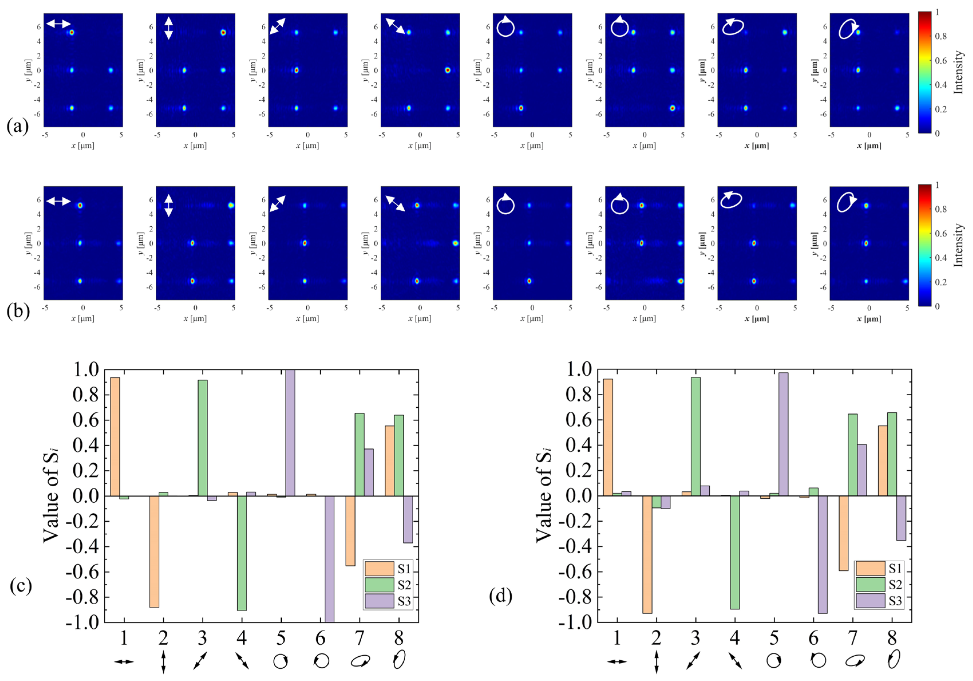
Figure 5a,b show the intensity distributions for different incident polarization states at −10° and −20° along the x-direction, respectively. It should be noted that two elliptical polarized lights are randomly chosen as the incident lights to demonstrate the applicability of the calculated modified coefficients. The S1~S3 parameters of incident light are (−0.6, 0.693, 0.4) T and (0.6, 0.693, −0.4) T, respectively. Figure 5c,d are the calculated normalized Stokes parameters with corresponding modified coefficients, respectively. The calculated Stokes parameters show good agreement with the original values. As the angle of incidence increases, the quality of the results decreases slightly. The average absolute value errors at −10°and −20° are, respectively, 0.035 and 0.047. The maximum error is 0.09 at −20° incidence. As in previous discussions in the case of vertical incident, the maximum error is randomly generated due to the approximate expression of the phase modulation and the margin of error of the computer. However, compared with Ref. [29], the proposed structure in this paper has almost the same measurement accuracy.
4. Conclusions
In conclusion, an efficient dielectric metasurface-based polarimetry is proposed in this paper. The structure realizes the measurement of the tilt incident angle and characterizes the full Stokes vector of the incident light in the angle range of ±20°. The maximum calculation error of the tilt angle is about 0.5°. The Stokes vector maximum error is less than 0.09 at normal incidence and is about 0.1 at −20° incidence. The calculated results also show a small average absolute value error of about 0.052 at −20° incidence. Additionally, according to our design method, the range of measurable incident angles can be expanded by adjusting the metasurface areas and focal lengths. Since the metasurface can be integrated with complementary metal oxide semiconductors (CMOS), further experiments will be conducted in the future to verify the stability of the proposed structure. We believe that the proposed metasurface-based polarimetry has potential applications in the fields of polarization imaging and object recognition, especially in underwater environments.
Supplementary Materials
The following supporting information can be downloaded at: https://www.mdpi.com/article/10.3390/photonics10040382/s1, Table S1: Structure parameters of the polarimetry.
Author Contributions
Conceptualization and methodology, S.L., Z.Z. and J.C.; software, validation, formal analysis, and investigation, S.L. and J.C.; resources, Z.Z., J.C. and X.W.; data curation and visualization, S.L.; writing—original draft preparation, S.L., Z.Z., X.W. and S.S.; writing—review and editing, S.L., Z.Z., S.S., X.W. and J.X.; supervision and project administration, Z.Z.; funding acquisition, Z.Z. All authors have read and agreed to the published version of the manuscript.
Funding
This research was funded by the National Natural Science Foundation of China (NSFC), grant number 62101487, and in part by the Zhoushan-Zhejiang University Joint Research Project, grant number 2020C81006.
Institutional Review Board Statement
Not applicable.
Informed Consent Statement
Not applicable.
Data Availability Statement
Not applicable.
Conflicts of Interest
The authors declare no conflict of interest.
References
- Dupeyroux, J.; Serres, J.R.; Viollet, S. AntBot: A six-legged walking robot able to home like desert ants in outdoor environments. Sci. Robot. 2019, 4, eaau0307. [Google Scholar] [CrossRef] [Green Version]
- Tyo, J.S.; Goldstein, D.L.; Chenault, D.B.; Shaw, J.A. Review of passive imaging polarimetry for remote sensing applications. Appl. Opt. 2006, 45, 5453–5469. [Google Scholar] [CrossRef] [PubMed] [Green Version]
- Dou, C.; Wang, S.; Zhang, Z.; Huang, Y.; Yang, X.; Li, B. The design of atmosphere polarimetry sensing with multi-bands. Opt. Commun. 2018, 410, 863–866. [Google Scholar] [CrossRef]
- Okoshi, T.; Kikuchi, K. Coherent Optical Fiber Communications; Springer Science & Business Media: Berlin/Heidelberg, Germany, 1988; Volume 4. [Google Scholar]
- Antonelli, M.-R.; Pierangelo, A.; Novikova, T.; Validire, P.; Benali, A.; Gayet, B.; De Martino, A. Mueller matrix imaging of human colon tissue for cancer diagnostics: How Monte Carlo modeling can help in the interpretation of experimental data. Opt. Express 2010, 18, 10200–10208. [Google Scholar] [CrossRef] [PubMed]
- Zhou, H.; Li, J.; Liao, R.; Chen, Y.; Liu, T.; Wang, Y.; Zhang, X.; Ma, H. Profile probing of suspended particles in water by Stokes vector polarimetry. Opt. Express 2022, 30, 14924–14937. [Google Scholar] [CrossRef]
- Shen, Y.; Lin, W.; Wang, Z.; Li, J.; Sun, X.; Wu, X.; Wang, S.; Huang, F. Rapid detection of camouflaged artificial target based on polarization imaging and deep learning. IEEE Photonics J. 2021, 13, 1–9. [Google Scholar] [CrossRef]
- Liu, T.; Yu, S.; Zhu, X.; Liao, R.; Zhuo, Z.; He, Y.; Ma, H. In-situ Detection Method for Microplastics in Water by Polarized Light Scattering. Front. Mar. Sci. 2021, 8, 739683. [Google Scholar] [CrossRef]
- Arteaga, O.; Kahr, B. Mueller matrix polarimetry of bianisotropic materials. J. Opt. Soc. Am. B 2019, 36, F72–F83. [Google Scholar] [CrossRef]
- Azzam, R. Photopolarimeter using two modulated optical rotators. Opt. Lett. 1977, 1, 181–183. [Google Scholar] [CrossRef]
- Gori, F. Measuring Stokes parameters by means of a polarization grating. Opt. Lett. 1999, 24, 584–586. [Google Scholar] [CrossRef]
- Krishnan, S.; Hampton, S.; Rix, J.; Taylor, B.; Azzam, R.M. Spectral polarization measurements by use of the grating division-of-amplitude photopolarimeter. Appl. Opt. 2003, 42, 1216–1227. [Google Scholar] [CrossRef] [PubMed] [Green Version]
- Pezzaniti, J.L.; Chenault, D.B. A division of aperture MWIR imaging polarimeter. In Proceedings of the Polarization Science and Remote Sensing II, San Diego, CA, USA, 31 July–4 August 2005; pp. 239–250. [Google Scholar]
- York, T.; Gruev, V. Characterization of a visible spectrum division-of-focal-plane polarimeter. Appl. Opt. 2012, 51, 5392–5400. [Google Scholar] [CrossRef] [PubMed]
- Zhang, L.; Mei, S.; Huang, K.; Qiu, C.W. Advances in full control of electromagnetic waves with metasurfaces. Adv. Opt. Mater. 2016, 4, 818–833. [Google Scholar] [CrossRef]
- Hsiao, H.H.; Chu, C.H.; Tsai, D.P. Fundamentals and applications of metasurfaces. Small Methods 2017, 1, 1600064. [Google Scholar] [CrossRef] [Green Version]
- Overvig, A.C.; Shrestha, S.; Malek, S.C.; Lu, M.; Stein, A.; Zheng, C.; Yu, N. Dielectric metasurfaces for complete and independent control of the optical amplitude and phase. Light Sci. 2019, 8, 92. [Google Scholar] [CrossRef] [PubMed] [Green Version]
- Myhre, G.; Hsu, W.-L.; Peinado, A.; LaCasse, C.; Brock, N.; Chipman, R.A.; Pau, S. Liquid crystal polymer full-stokes division of focal plane polarimeter. Opt. Express 2012, 20, 27393–27409. [Google Scholar] [CrossRef]
- Mueller, J.P.B.; Rubin, N.A.; Devlin, R.C.; Groever, B.; Capasso, F. Metasurface Polarization Optics: Independent Phase Control of Arbitrary Orthogonal States of Polarization. Phys. Rev. Lett. 2017, 118, 113901. [Google Scholar] [CrossRef] [Green Version]
- Yu, N.; Genevet, P.; Kats, M.A.; Aieta, F.; Tetienne, J.-P.; Capasso, F.; Gaburro, Z. Light propagation with phase discontinuities: Generalized laws of reflection and refraction. Science 2011, 334, 333–337. [Google Scholar] [CrossRef] [Green Version]
- Yu, N.; Capasso, F. Flat optics with designer metasurfaces. Nat. Mater. 2014, 13, 139–150. [Google Scholar] [CrossRef]
- Zheng, G.; Mühlenbernd, H.; Kenney, M.; Li, G.; Zentgraf, T.; Zhang, S. Metasurface holograms reaching 80% efficiency. Nat. Nanotechnol. 2015, 10, 308–312. [Google Scholar] [CrossRef]
- Kamali, S.M.; Arbabi, E.; Arbabi, A.; Faraon, A. A review of dielectric optical metasurfaces for wavefront control. Nanophotonics 2018, 7, 1041–1068. [Google Scholar] [CrossRef]
- Erçağlar, V.; Hajian, H.; Serebryannikov, A.E.; Ozbay, E. Multifunctional tunable gradient metasurfaces for terahertz beam splitting and light absorption. Opt. Lett. 2021, 46, 3953–3956. [Google Scholar] [CrossRef]
- Park, C.-S.; Koirala, I.; Gao, S.; Shrestha, V.R.; Lee, S.-S.; Choi, D.-Y. Structural color filters based on an all-dielectric metasurface exploiting silicon-rich silicon nitride nanodisks. Opt. Express 2019, 27, 667–679. [Google Scholar] [CrossRef] [PubMed]
- Pors, A.; Nielsen, M.G.; Bozhevolnyi, S.I. Plasmonic metagratings for simultaneous determination of Stokes parameters. Optica 2015, 2, 716–723. [Google Scholar] [CrossRef] [Green Version]
- Guo, Z.; Xu, H.; Guo, K.; Shen, F.; Zhou, H.; Zhou, Q.; Gao, J.; Yin, Z. High-efficiency visible transmitting polarizations devices based on the GaN metasurface. Nanomaterials 2018, 8, 333. [Google Scholar] [CrossRef] [Green Version]
- Arbabi, E.; Kamali, S.M.; Arbabi, A.; Faraon, A. Full-Stokes imaging polarimetry using dielectric metasurfaces. ACS Photonics 2018, 5, 3132–3140. [Google Scholar] [CrossRef] [Green Version]
- Zhang, Y.; Jin, J.; Pu, M.; He, Q.; Guo, Y.; Li, X.; Ma, X.; Luo, X. Full Stokes Polarimetry for Wide-Angle Incident Light. Phys. Status Solidi-Rapid Res. Lett. 2020, 14, 2000044. [Google Scholar] [CrossRef]
- Solonenko, M.G.; Mobley, C.D. Inherent optical properties of Jerlov water types. Appl. Opt. 2015, 54, 5392–5401. [Google Scholar] [CrossRef]
- Liu, J.; Zhang, R.; Fan, Y.; Cheng, H.; Guan, C.; Chu, J. A novel method for the design of a full Stokes polarimeter based on dielectric metasurfaces. Optik 2022, 261, 169198. [Google Scholar] [CrossRef]
- Li, X.; Wang, H.; Xu, X.; Ju, L.; Fan, Z.; Chen, S. Mid-infrared full-Stokes polarization detection based on dielectric metasurfaces. Opt. Commun. 2021, 484, 126690. [Google Scholar] [CrossRef]
- Yu, G.; Wang, G.; Ishikawa, H.; Umeno, M.; Soga, T.; Egawa, T.; Watanabe, J.; Jimbo, T. Optical properties of wurtzite structure GaN on sapphire around fundamental absorption edge (0.78–4.77 eV) by spectroscopic ellipsometry and the optical transmission method. Appl. Phys. Lett. 1997, 70, 3209–3211. [Google Scholar] [CrossRef]
Figure 1.
The schematic diagram of two Cartesian coordinate systems, xyz and x’y’z’.

Figure 2.
(a) Schematic diagram of the metasurface unit; (b) Schematic diagram of the principle of the polarimetry; (c) Side view of the focusing effect of the polarimetry; (d) The influence of the length, l, and width, w, of the nanopillars on the transmittance; (e) The effect of the length, l, and width, w, of the nanopillars on the x-polarization phase shift; (f) Phase values and corresponding to nanopillar dimensions.

Figure 3.
(a) The intensity distributions of the six vertically incident polarized lights (i.e., x-LP, y-LP, 45°-LP, 135°-LP, RCP, and LCP) on the focal plane with ; (b) The calculated normalized Stokes parameters for different polarization states; (c) The wavelength dependence of the structure transmittance; (d) The y-polarized light intensity of Part I on the fixed focal plane with different wavelengths.

Figure 4.
(a) Schematic diagram of oblique incidence scenario; (b,c) Schematic diagrams of the inclination angle ±θ along the x-axis direction, respectively; (d) The focal intensity distribution of y-polarized light of Part I on the focal plane with different incident angle (0°, −5°, −10°, −15°, and −20°); (e) The relationship between the calculated incident angle and the actual incident angle, as well as the absolute value of the error. Intensity distributions of the transmitted light with the oblique incident angle of (f,g) −20° and 20° along the y-axis, (h,i) −20° and 20° along the x-axis, respectively.

Figure 5.
The intensity distributions of different incident polarization states at (a) −10° and (b) −20°. The calculated normalized modified Stokes parameters of different polarization states at incident angles of (c) −10° and (d) −20°.
Figure 5.
The intensity distributions of different incident polarization states at (a) −10° and (b) −20°. The calculated normalized modified Stokes parameters of different polarization states at incident angles of (c) −10° and (d) −20°.

Disclaimer/Publisher’s Note: The statements, opinions and data contained in all publications are solely those of the individual author(s) and contributor(s) and not of MDPI and/or the editor(s). MDPI and/or the editor(s) disclaim responsibility for any injury to people or property resulting from any ideas, methods, instructions or products referred to in the content. |
© 2023 by the authors. Licensee MDPI, Basel, Switzerland. This article is an open access article distributed under the terms and conditions of the Creative Commons Attribution (CC BY) license (https://creativecommons.org/licenses/by/4.0/).
Share and Cite
MDPI and ACS Style
Liu, S.; Zhang, Z.; Cheng, J.; Wang, X.; Sun, S.; Xu, J. Design of Full Stokes Vector Polarimetry Based on Metasurfaces for Wide-Angle Incident Light. Photonics 2023, 10, 382. https://doi.org/10.3390/photonics10040382
AMA Style
Liu S, Zhang Z, Cheng J, Wang X, Sun S, Xu J. Design of Full Stokes Vector Polarimetry Based on Metasurfaces for Wide-Angle Incident Light. Photonics. 2023; 10(4):382. https://doi.org/10.3390/photonics10040382
Chicago/Turabian StyleLiu, Songjie, Zejun Zhang, Jingxuan Cheng, Xiyin Wang, Shixiao Sun, and Jing Xu. 2023. "Design of Full Stokes Vector Polarimetry Based on Metasurfaces for Wide-Angle Incident Light" Photonics 10, no. 4: 382. https://doi.org/10.3390/photonics10040382
Note that from the first issue of 2016, this journal uses article numbers instead of page numbers. See further details here.