Generation, Topological Charge, and Orbital Angular Momentum of Off-Axis Double Vortex Beams


1
Advanced Photonics Center, Southeast University, Nanjing 210096, China
2
School of Computer and Electronic Information, Nanjing Normal University, Nanjing 210023, China
3
School of Physics and Electronics, Central South University, Changsha 410012, China
4
Collaborative Innovation Center of Light Manipulations and Applications, Shandong Normal University, Jinan 250358, China
*
Author to whom correspondence should be addressed.
Photonics 2023, 10(4), 368; https://doi.org/10.3390/photonics10040368
Submission received: 1 March 2023
/
Revised: 21 March 2023
/
Accepted: 23 March 2023
/
Published: 25 March 2023
(This article belongs to the Special Issue Advances and Application of Structured Light)
Abstract
:Compared with the on-axis vortex beam and the off-axis single vortex beam, the off-axis double vortex beam has more control degrees of freedom and brings rich physical properties. In this work, we investigate theoretically and experimentally the generation, topological charge (TC), and orbital angular momentum (OAM) of off-axis double vortex beams. It is demonstrated that the tilted lens method can detect not only the magnitudes and signs of two TCs of the off-axis double vortex beam but also the spatial distribution of the TCs. Moreover, the average OAM value of the off-axis double vortex beam decreases nonlinearly as the off-axis distance increases, although its TC is independent of the off-axis distance of phase singularities. The results indicate that the average OAM of the off-axis double vortex beam can be easily controlled by changing the relative position of two-phase singularities, thereby realizing the applications of multi-degrees of freedom particle manipulation, optical communication, and material processing.
1. Introduction
A vortex beam refers to the optical vortex with the phase term of exp(imϕ), where m is the azimuthal index and ϕ is the azimuthal angle in the cylindrical coordinate system [1]. This kind of light beam with phase singularity and spiral wavefront has received extensive attention since Allen et al. [2] confirmed the vortex beam carrying orbital angular momentum (OAM). In the past 30 years, many types of vortex beams, such as integer order vortex beams [2], fractional order vortex beams [3], grafted vortex beams [4], and perfect vortex beams [5], have been generated by using spiral phase plates [6], fork gratings [7], spatial light modulators (SLMs) [8], and digital micro-mirror devices [9]. At the same time, researchers have widely investigated the physical properties of vortex beams [10] and developed their technological applications in particle micromanipulation [3,11], optical communication [12], quantum communication [13], high-resolution microscopy [14], material processing [15], and optical measurements [16].
It is usually focused on the on-axis vortex beam whose phase singularity coincides with the center of the beam. This conventional vortex beam has an axis-symmetric annular intensity distribution. However, when a spiral phase plate [6] or fork grating [7] is used to create vortex beams, due to the existence of alignment errors, the phase singularity of vortex beams has a certain off-axis distance from the optical axis, generating off-axis vortex beams. This off-axis vortex beam breaks the axial symmetry of the light field, resulting in many novel physical properties and applications [17,18,19,20,21,22,23,24]. For example, Kovalev et al. [18] reported that by trapping and moving the microspheres at the focus of an asymmetric Laguerre–Gaussian laser beam, the velocity of microspheres increases with increasing the asymmetry parameter at the fixed topological charge (TC). Zhao et al. [19] studied the tightly focused Gaussian beam with an off-axis vortex and found that the off-axis vortex induces a rotation of the intensity pattern, the transverse focal shift, and the asymmetric distribution of the phase singularities. Kovalev et al. [20] demonstrated that the OAM decreases with the increase of the off-axis distance of the asymmetric Gaussian optical vortex. Alam et al. [21] generated and controlled the OAM spectrum of the asymmetric vortex beams in a nonlinear frequency conversion process. Kovalev et al. [23] investigated the OAM and TC of a Gaussian beam with several embedded phase singularities uniformly arranged on a circle. As mentioned above, compared with the on-axis vortex beam, the off-axis vortex beam has more control degrees of freedom and brings the rich physical properties.
There are two important parameters to describe the physical properties of the vortex beam, namely, TC and average OAM. The TC and the average OAM quantitatively characterize the strength of phase singularity and the OAM carried by the vortex beam, respectively. In the past decades, many methods have been proposed to measure the TC of an unknown vortex beam, such as using a triangular aperture [25], an annular ellipse aperture [26], a tilted convex lens [27], a twisting phase [28], a focal hyperbolic lens [29], a single plate [30], and a cylindrical lens [31]. It is noteworthy that the existing TC detection methods are generally used for the characterization of single-phase singularities and rarely involve the TC detection of multi-phase singularities in the vortex beam. At the same time, researchers have developed a variety of OAM measurement methods, including the vortex beam interfering with the Gaussian reference beam [32], the camera measuring the focal field intensity distribution of the vortex beam after passing through the cylindrical lens [33,34,35], and the geometric phase transformation from spiral to linear using an SLM [36]. It is well documented that the average OAM value of the on-axis vortex beam is equal to the TC. However, in the asymmetric light fields (e.g., off-axis single vortex beam), the average OAM is no longer equal to the TC [20,23,37]. As such, many recent efforts have focused on the TC and OAM of off-axis vortex beams. Although the physical properties of off-axis single vortex beams have been extensively studied, the investigation on off-axis multi-vortex beams is relatively less [38]; the dependence of off-axis distance on its TC and OAM, in particular, needs further study.
In this work, we design and generate off-axis double vortex beams with different off-axis distances and different azimuthal indices, detect their TCs theoretically and experimentally using the tilted lens method, and measure their average OAM using the cylindrical lens method. It is shown that the average OAM value of the off-axis double vortex beam decreases nonlinearly as the off-axis distance increases, although its TC is independent of the off-axis distance of phase singularities. The results indicate that the average OAM of the off-axis double vortex beam can be easily controlled by changing the relative position of two phase singularities, thereby realizing the applications of multi-degrees of freedom particle manipulation, optical communication, and material processing.
2. Generation of Off-Axis Double Vortex Beams
2.1. Mathematical Description
Let us consider an on-axis vortex beam whose phase singularity is located at the geometric center of the beam (i.e., the coordinate origin (x0, y0) = (0, 0)). In the Cartesian coordinate system, the linearly polarized on-axis vortex beam at the plane of z = 0 can be simply expressed as [2,17]
where E0 is an amplitude constant, m is the azimuthal index, and w is the waist radius of the fundamental Gaussian beam. When m is positive, the sign of y is positive, and vice versa. As shown in Figure 1a, the intensity distribution of the on-axis vortex beam maintains cylindrical symmetry.
When the on-axis vortex beam is shifted by x1 along the x-axis and y1 along the y-axis, as shown in Figure 1b, an off-axis single vortex beam will be obtained. It is noteworthy that the amplitude distribution of the off-axis single vortex beam presents a cylindrical symmetry breaking, and its phase singularity located at (x1, y1) deviates from the geometric center (0, 0) (see Figure 1e). The electric field of the linearly polarized off-axis single vortex beam can be described as [17]
Especially when the phase singularity approaches the geometric center of the beam, Equation (2) degenerates into Equation (1).
Based on the off-axis single vortex beam, the off-axis double vortex beam can be regarded as the superposition of two off-axis single vortex beams [17]. Accordingly, the complex amplitude of the linearly polarized off-axis double vortex beam can be written as
Here, m1 and m2 are the azimuthal indices of off-axis double vortexes with two phase singularities located at (x1, y1) and (x2, y2), respectively.
As shown in Figure 1, there is an adjustable parameter m in the on-axis vortex beam, three adjustable parameters m, x1, and y1 in the off-axis single vortex beam, and six adjustable parameters m1, m2, x1, y1, x2, and y2 in the off-axis double vortex beam. Clearly, by adjusting the two pairs of independent variables (i.e., the azimuthal index mj, the positions located at two phase singularities (xj, yj) where j = 1, 2) of the off-axis double vortex beam, one will exploit its rich physical properties. Note that the presented off-axis double vortex beam has two main differences from the on-axis double vortex beam: (i) off-axis and on-axis double vortex beams have six and two adjustable parameters, respectively; (ii) on-axis double vortex beams cannot carry a pair of phase singularities with opposite TC signs, while off-axis double vortex beams can.
2.2. Experimental Arrangement
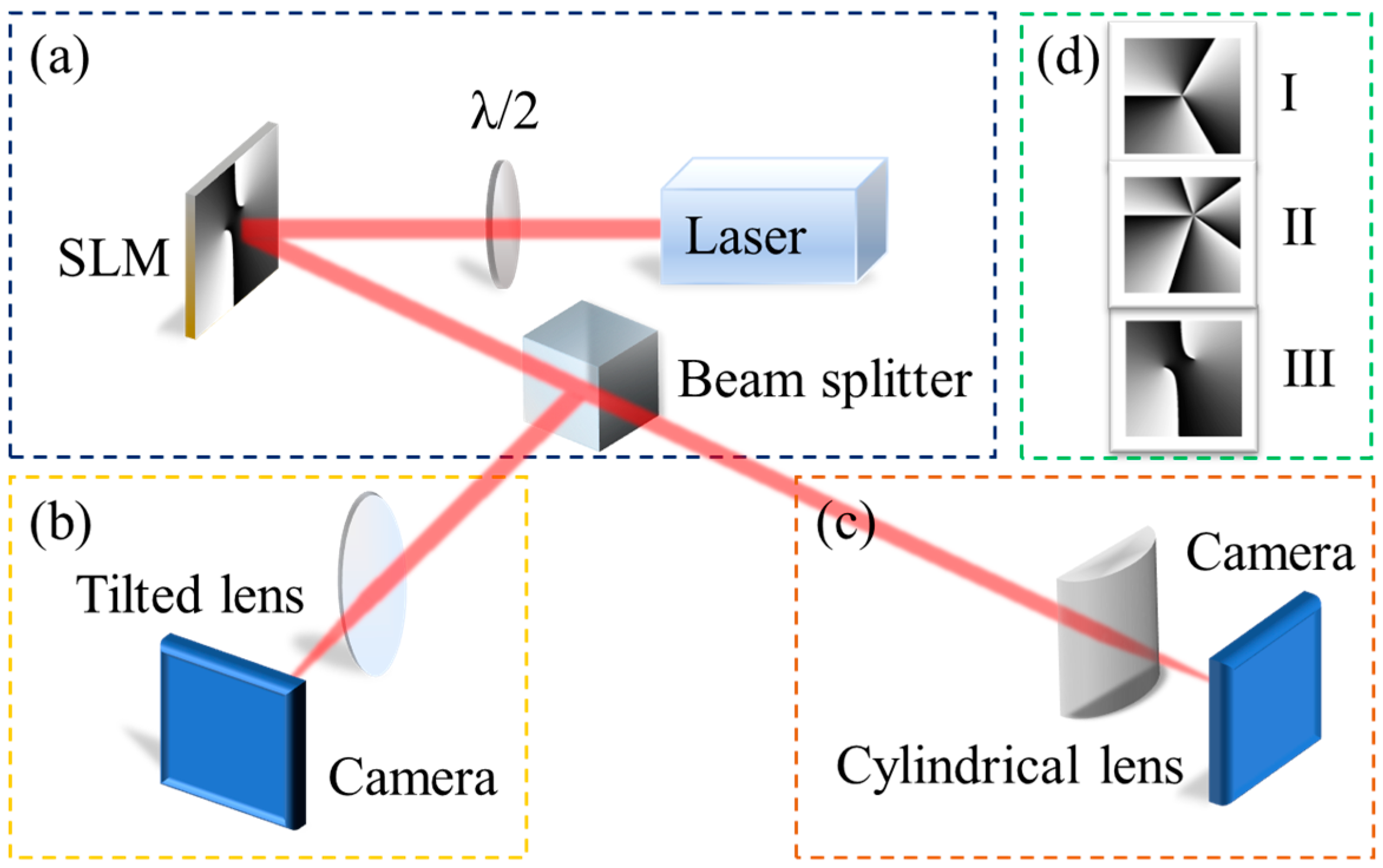
To study the above-mentioned vortex beams, we carry out the experiments. As shown in Figure 2, the experimental setup consists of three parts: the generation of the vortex beams, TC detection, and OAM measurement.
The first part shown in Figure 2a is the generation unit of vortex beams, which includes a laser source, a λ/2 wave plate, and an SLM. The laser source is a continuous-wave laser beam with a Gaussian spatial profile at the wavelength of λ = 1064 nm. The collimated laser beam comes into a λ/2 wave plate. By adjusting the fast axis orientation of the λ/2 wave plate, the linear polarization direction of the beam is matched with the polarization response of the SLM. Then, the laser beam is modified by the phase mask displayed in the reflective phase-only SLM (HOLOEYE, PLUTO) to obtain the desired linearly polarized vortex beam. For example, Figure 2d shows three typical phase masks projected on the SLM, which are used to generate (I) on-axis vortex, (II) off-axis single vortex, and (III) off-axis double vortex beams, respectively. The intensity distribution of the generated vortex beam is measured by a camera.
In the second part, as shown in Figure 2b, the generated vortex beam passes through a titled convex lens, and its intensity distribution near the focal plane of the tilted lens is measured by a camera. By analyzing the number and orientation of intensity stripes, both the magnitude and sign of the TC of generated vortex beams can be detected intuitively [27].
The third part shown in Figure 2c is the OAM measurement unit of vortex beams. The generated vortex beam passes through a cylindrical lens. The average OAM of the generated vortex beam can be measured quantitatively by analyzing the intensity image monitored by the camera at the focal plane of the cylindrical lens [34]. For the asymmetric beam carrying the OAM, the experimental setup should be calibrated, and the cylindrical lens should be rotated to an appropriate angle [34].
2.3. Results and Discussion
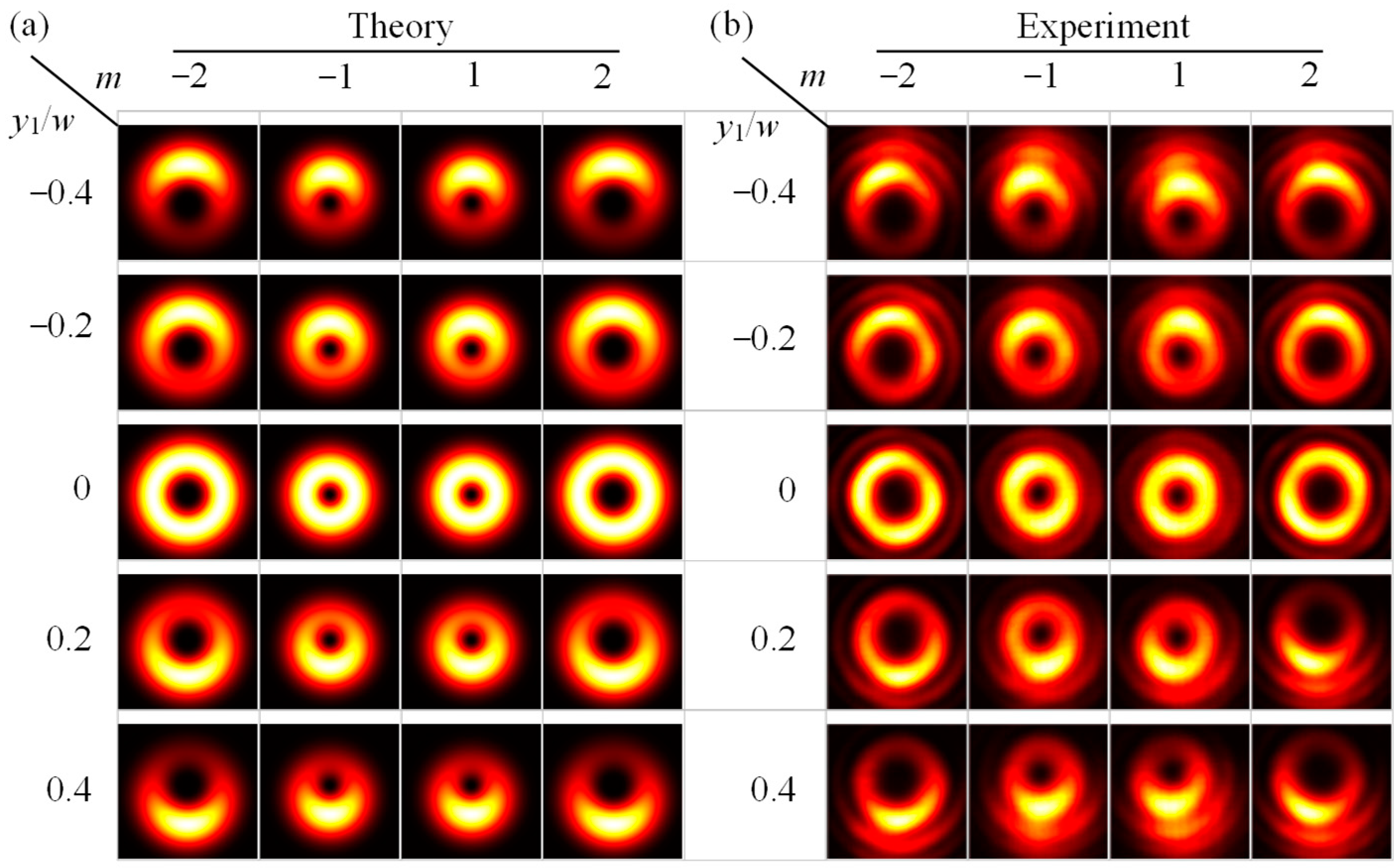
First, we study the intensity distributions of off-axis single vortex beams with the change of off-axis distance and azimuthal index. Figure 3 shows the theoretically simulated and experimentally measured intensity patterns of off-axis single vortex beams with different values of y1 and m when w = 2.5 mm and x1 = 0. Clearly, the theoretically simulated intensity patterns (see Figure 3a) of off-axis single vortex beams are in good agreement with the experimentally measured results (see Figure 3b). Compared with the axially symmetric on-axis vortex beam (i.e., y1 = 0), the phase singularity of the off-axis single vortex beam is not at the geometric center of the beam, and the symmetry of its intensity distribution is broken. Moreover, with the increase of the off-axis distance |y1|, this symmetry breaking becomes more serious, resulting in the intensity distribution of the off-axis single vortex beams changing from a doughnut-shaped pattern to a crescent-shaped pattern. In addition, as the azimuthal index |m| increases, the phase singularity region of the off-axis vortex beam increases.
As illustrated in Figure 1, the off-axis double vortex beam has rich intensity patterns because it has more adjustable free parameters than the off-axis single vortex beam, including the position of two phase singularities and the magnitude and sign of two azimuthal indices. For simplicity, we only consider that two off-axis phase singularities are symmetric about the geometric center, and three points are on the same line. The distance between two phase singularities is Δ, that is, one phase singularity is located at −Δ/2, and the other is at +Δ/2.
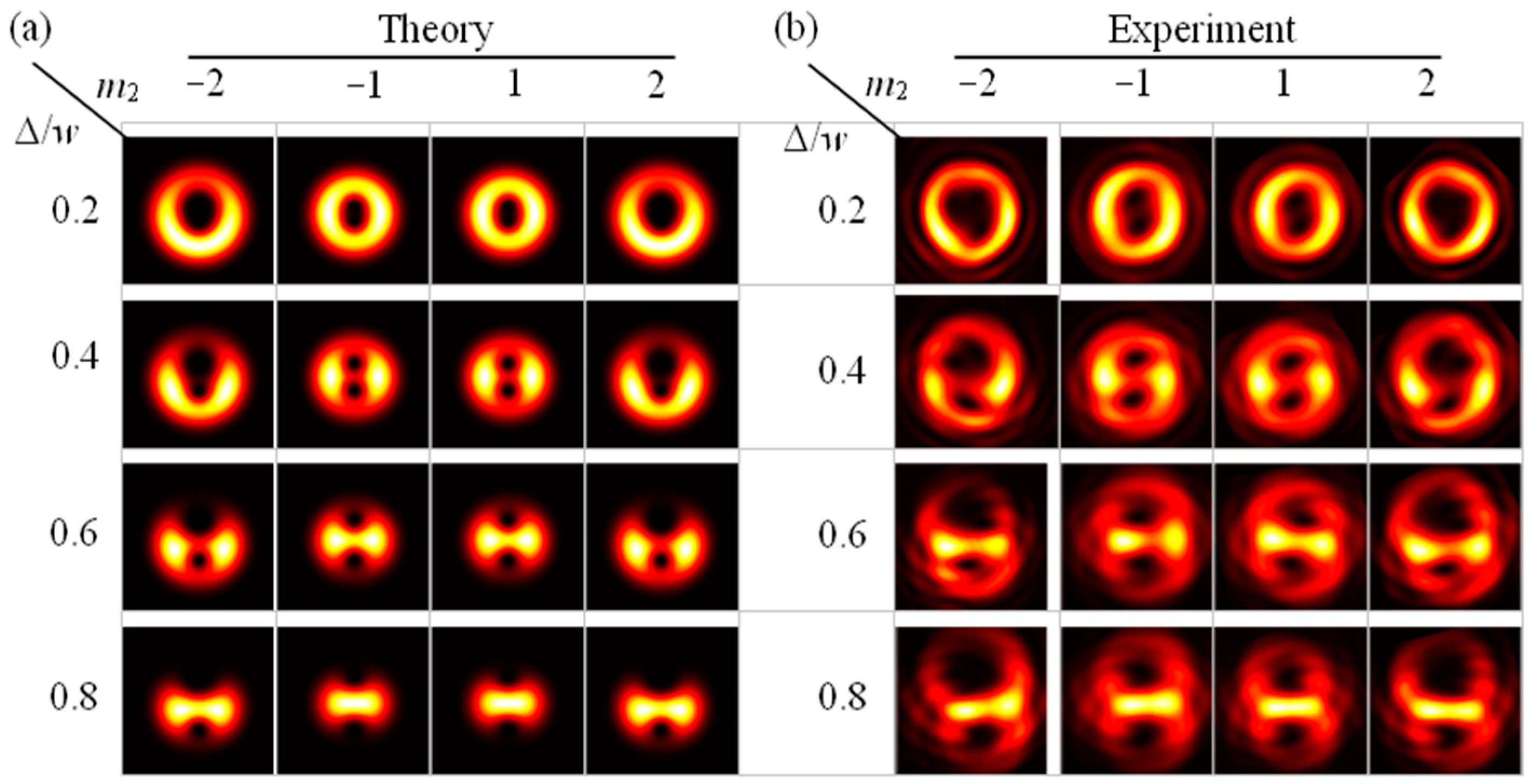
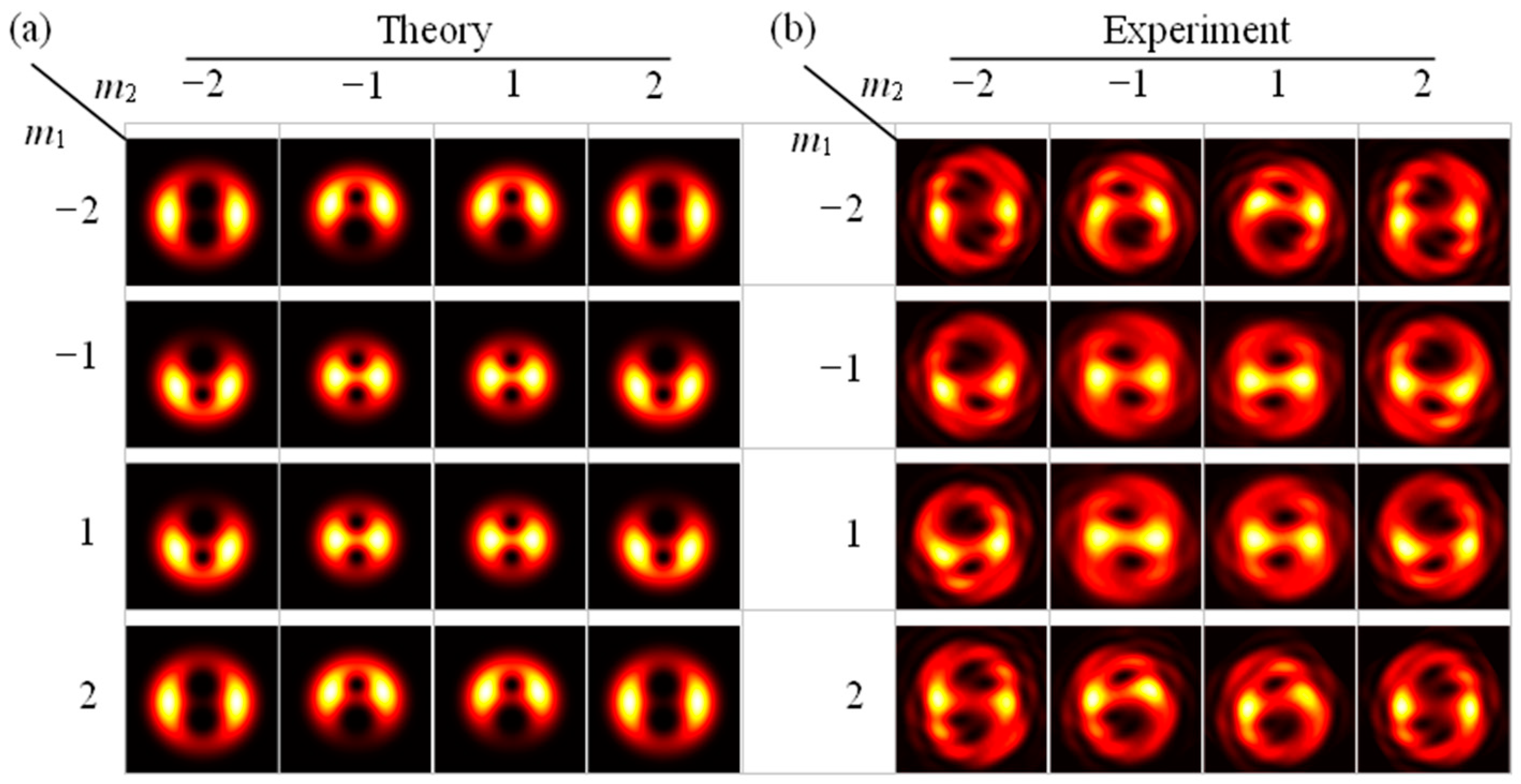
Figure 4 shows the intensity patterns of off-axis double vortex beams with different values of Δ and m2 when w = 2.5 mm, x1 = x2 = 0, and m1 = 1. When the parameters are taken as Δ = 0.5 w and x1 = x2 = 0, the intensity patterns of off-axis double vortex beams with different azimuthal indices m1 and m2 are shown in Figure 5. Obviously, for the off-axis double vortex beams shown in Figure 4 and Figure 5, their theoretically simulated intensity patterns are basically consistent with the experimentally measured results. The reason for the difference is that the centers of two off-axis phases loaded on the imperfect Gaussian beam in the experiments are not completely symmetrical about the beam’s geometric center. In addition, it is found that two phase singularities of the off-axis double vortex beam propagate stably in free space. As shown in Figure 4 and Figure 5, all off-axis double vortex beams have mirror symmetric intensity distribution. Especially when |m1| = |m2|, the intensity distribution of this off-axis double vortex beam maintains the two-fold rotational symmetry. Furthermore, with the increase of Δ value, the intensity distribution of this vortex beam changes from a doughnut-shaped pattern to a bowtie-shaped pattern. It is noteworthy that the intensity distribution of the off-axis single and double vortex beams (see Figure 3 and Figure 4) is only related to the position of phase singularities and the magnitude of azimuthal indices but is independent of the sign of these azimuthal indices. Therefore, the sign of the azimuthal index cannot be directly determined from the intensity distribution of the off-axis vortex beam. It is very necessary to develop other methods to identify the magnitude, sign, and distribution of the azimuthal index of the off-axis vortex beam.
3. TCs of Off-Axis Double Vortex Beams
3.1. Calculation of the TC
In general, the TC of a vortex beam is given by [39]
where (r, φ) are the polar coordinates. For an x-polarized beam in the Cartesian coordinate system, Equation (4) can be rewritten as
where Im[·] represents the imaginary part.
For an on-axis vortex beam or an off-axis single vortex beam, substituting Equations (1) or (2) into Equation (5), one gets [40]
Equation (6) suggests the following two points: (i) the TCs of the on-axis and off-axis vortex beams are equal to their azimuthal index; (ii) no matter whether the phase singularity is loaded at the center or the edge of the Gaussian beam, the TC of the single vortex beam is always m. Therefore, when the phase singularity is shifted in the vortex beam, the beam’s TC remains unchanged [23].
Substitution of Equation (3) into Equation (5) obtains the TC of the off-axis double vortex beam
As described by Equation (7), the TC of the off-axis double vortex beam is not only related to the magnitude of the azimuthal indices of two phase singularities but also related to their signs. Its value is equal to the sum of the azimuthal indices m1 and m2. It should be emphasized that if the magnitudes of two azimuthal indices are equal but the signs are opposite, this off-axis double vortex beam carries vortices, although the total TC is equal to zero. Consequently, the TC is not enough to describe the phase singularity of the off-axis double vortex beam, and the spatial distribution of the TC also needs to be known. In addition, it is worth noting that the TC of the vortex beam is usually independent of the propagation of the beam at different positions [23], which is the basis for detecting the TC of the vortex beam using the approaches such as interferometry [41], intensity analysis of vortex beams [42], and diffractometry [27].
3.2. Electric Field of the Off-Axis Vortex Beam Focused by a Tilted Convex Lens
In this work, a tilted convex lens is used to detect the TC of vortex beams. As shown in Figure 2b, the generated vortex beam is focused by the titled convex lens with a focal length of f and an inclination angle of θ after it travels for a distance z0 in free space. According to the Huygens–Fresnel integral formula, the electric field at the propagation distance z after the lens can be expressed as [27]
where
with
To obtain the analytical expressions of Equation (8), the binomial expansion of the incident electric field El(x,y) is required. Then, the integrations over x and y for an integer n ≥ 0 can be accomplished by the integral theorem
where Hn(i,β) is the Hermite polynomial of a complex argument. In this way, we obtain the analytical expression of the electric field at the propagation distance z after the titled lens as
where
Equations (12)–(14), which are the basic theoretical results of the present work, give the electric fields of three types of vortex beams at a given position through the tilted convex lens. Clearly, El(u,v) is an elliptical Gaussian beam modulated by Hermite polynomials. Therefore, at a certain position behind the lens, the intensity spots and their orientation give the magnitude and sign of the TC of the vortex beams, respectively [27]. Note that the obtained electric field EI(u,v) for the on-axis vortex beam is consistent with the one reported previously [27].
3.3. Detection of the TC
To verify the theory with experiments, the focusing intensity patterns of the off-axis vortex beams given in Figure 3, Figure 4 and Figure 5 after passing through the titled convex lens are shown in Figure 6, Figure 7 and Figure 8, respectively. The numerical simulations shown in Figure 6, Figure 7 and Figure 8 are obtained by Equations (12)–(14) with the optimal experimental parameters λ = 1064 nm, w = 2.5 mm, θ = π/9, f = 30 cm, z0 = 50 cm, and z = 32 cm. The intensity patterns near the focal plane of the tilted convex lens shown in Figure 6, Figure 7 and Figure 8 are measured by the experimental setup shown in Figure 2b. It is obvious that the theoretical simulations are consistent with the experimental measurements.
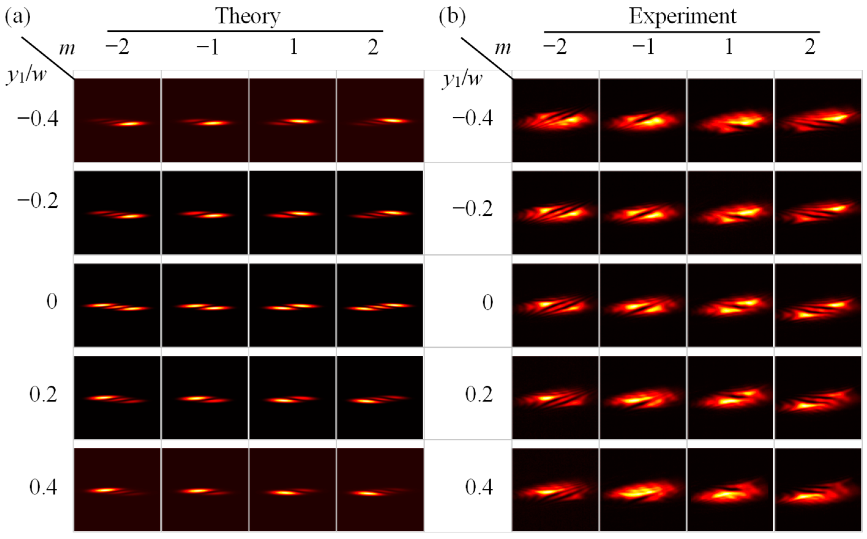
As shown in Figure 6, near the focus of the tilted convex lens, the intensity distribution of the off-axis single vortex beam presents a bright and dark striped shape, and the magnitude of the TC of the beam is equal to the number of bright stripes minus one. The direction of the stripes is related to the TC’s sign, and the corresponding stripes of vortex beams with different TC signs are inclined in opposite directions. When the phase singularity is located at the geometric center of the beam, the intensity distribution detected near the focus of the tilted lens is shown in the third line of Figure 6. Since the on-axis vortex beam is center symmetric, the intensity distribution of the inclined stripe is also uniform. In this case, the TC of on-axis vortex beams can be accurately measured by counting the number of inclined dark stripes. When the vortex is off-axis, as shown in Figure 6, the intensity of the inclined stripes will no longer be uniform, and the offset of the phase singularity results in the offset of intensity near the focal field of the tilted lens. Although the stripes are no longer uniform, the TC of an off-axis single vortex beam is still equal to the number of bright stripes minus one, which is the same as that of an on-axis vortex beam [27]. That is to say, the TC of off-axis single vortex beams is still equal to that of on-axis vortex beams (see Equation (6)).
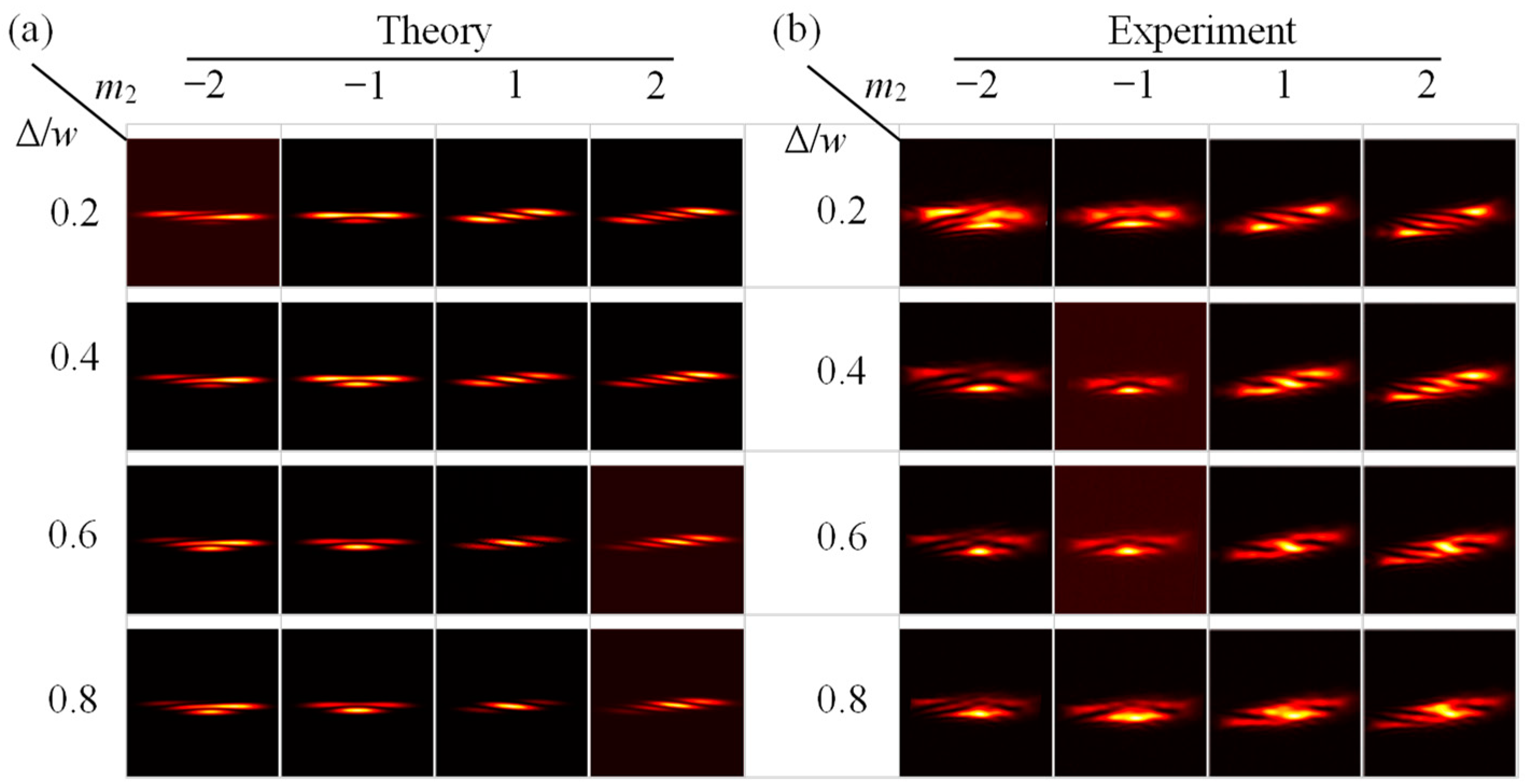
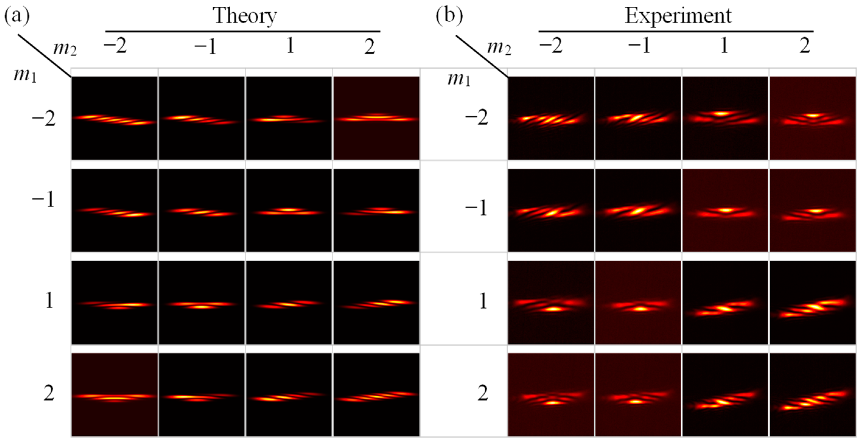
After discussing the off-axis single vortex beam, we focus on the TC detection of the off-axis double vortex beam. Figure 7 and Figure 8 show the theoretically simulated and experimentally measured intensity patterns of off-axis double vortex beams focused by the tilted convex lens. It is easy to find that the signs of two TCs m1 and m2 carried by the off-axis double vortex beam will have a significant impact on the intensity distribution focused by the tilted lens. If the signs of two TCs are the same, the number of dark inclined stripes is equal to the algebraic sum of their respective values. In contrast, if the signs of two TCs are opposite, the measured intensity distribution will be separated in space. For example, as shown in the first column of Figure 7, the left and right parts of the intensity distribution come from the contributions of TCs with negative and positive signs, respectively. Especially, in the first row and the second column of Figure 7, the number of dark stripes on the left and right sides of the intensity pattern is 1, which means that this vortex beam carries two vortices with TCs of −1 and +1, respectively. As shown in Figure 7, with the increase of the off-axis distance Δ, the intensity at both ends of the bright inclined stripes will be weakened, which will reduce the accuracy of the detected TC. The main reasons are analyzed as follows: when the off-axis distance Δ increases gradually, the intensity distribution of the off-axis double vortex beam changes from the ring type to the half-moon type, so the intensity of the bright stripes after the beam passes through the tilted lens will also be reduced, but the original phase singularity still exists. In short, we demonstrate theoretically and experimentally that the tilted lens method can detect not only the magnitudes and signs of two TCs of the off-axis double vortex beam but also the spatial distribution of the TCs. This is because when the signs of two TCs are opposite, the inclined stripes of the off-axis double vortex beam passing through the tilted lens are separated in space.
4. OAM of Off-Axis Double Vortex Beams
4.1. OAM Density and Average OAM
For an x-polarized electric field E(x, y) in Cartesian coordinates, the longitudinal OAM density normalized by the intensity can be expressed as [43]
where E*(x, y) denotes the complex conjugate of the electric field E(x, y).
For an on-axis vortex beam, substituting Equation (1) into Equation (19), one gets
It is obvious that the TC of the on-axis vortex beam is identical to the OAM density.
Substitution of Equation (2) into Equation (19) obtains the OAM density of the off-axis single vortex beam as
Clearly, the OAM density of the off-axis single vortex beam depends not only on the TC, but also on the distance from the phase singularity to the optical axis.
In a similar way, by substituting Equation (3) into Equation (19), we get the OAM density of the off-axis double vortex beam as
As described by Equation (22), the OAM density of the off-axis double vortex beam is equal to the superposition of the OAM density of two off-axis single vortex beams. Alternatively, the OAM density of the off-axis double vortex beam can be regarded as the weighted superposition of two TCs related to the spatial positions of the phase singularities.
The OAM carried by the vortex beam can be quantitatively expressed by the experimentally measurable quantity, namely, the average OAM [34]. The average OAM Lz is defined as the OAM of paraxial beams Jz normalized to power W [44]
with
where the integral area S is the detection area of the camera in the experiment.
It is well known that the average OAM of the on-axis vortex beam is Lz = m [44] by substituting Equation (1) in Equation (23). If Lz is multiplied by Planck’s constant, the OAM per photon carried by the conventional vortex beam can be obtained. However, for the off-axis single and double vortex beams, their average OAM value needs to be calculated numerically. Numerical simulation shows that the magnitude of the average OAM of the off-axis vortex beam decreases nonlinearly with the increase of off-axis distance. When the phase singularity is close to the beam center (i.e., xj→0 and yj→0), the average OAM is close to the TC. On the contrary, the average OAM tends to be zero when the off-axis distance is large (i.e., xj→∞ and yj→∞).
4.2. Average OAM Measurement
Experimentally, the setup shown in Figure 2c is used to measure the average OAM of the off-axis vortex beam quantitatively. In our experiment, the focal length of the cylindrical lens is f = 150 mm, the laser wavelength is λ = 1064 nm, the waist radius of the off-axis vortex beam is w = 2.5 mm, and the angle between the optical axis of the cylindrical lens and the x-axis of the vortex beam is approximately 45°. The details for the average OAM measurement can be found elsewhere [34]. Quantitatively, the average OAM of the generated vortex beam can be measured by [34]
where |E(x′, y)|2 is the intensity distribution at the focal plane of the cylindrical lens.
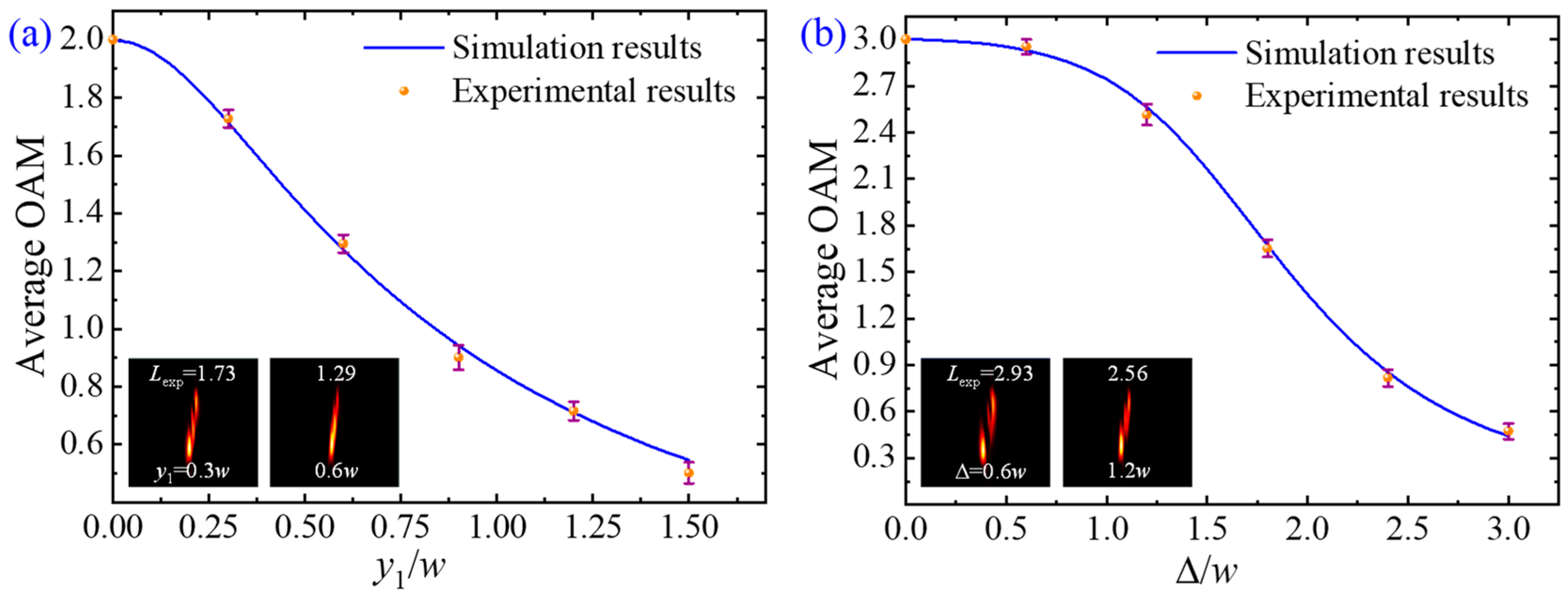
The average OAM values of the off-axis vortex beams are obtained from the experimentally measured intensity distributions (see the inserts in Figure 9) with the help of Equation (26). For example, Figure 9a,b show the measured average OAM values as a function of off-axis distance for the off-axis single vortex beam (m = 2 and x1 = 0) and off-axis double vortex beam (m1 = 1, m2 = 2, and x1 = x2 = 0), respectively. The numerical simulations by Equation (23) are also plotted in Figure 9. Apparently, the measured OAM values are in good agreement with the theoretical results. It is shown that the average OAM value decreases nonlinearly as the off-axis distance (y1 or Δ) increases. This result can be understood as follows: the average OAM value of off-axis single Gaussian vortex beams is Lz = mexp[−2(r0/w)2], which decreases nonlinearly as the off-axis distance r0 increases [20,22]. As described in Equation (3), an off-axis double vortex beam is equivalent to the superposition of two off-axis single vortex beams. Obviously, OAM density (see Equation (22)) and average OAM have similar conclusions. When the phase singularity is close to the beam center, the average OAM value is approximately equal to the TC. When the off-axis distance Δ is large, the average OAM trends to zero, although the TC of the off-axis single and double vortex beams is independent of the off-axis distance of the phase singularities. The results show that changing the off-axis distance of the off-axis vortex beam can easily manipulate the average OAM of the vortex beam, thereby realizing the applications of particle manipulation, optical communication, etc.
5. Conclusions
In summary, we have designed and generated the off-axis double vortex beams. It is demonstrated that compared with the traditional vortex beam, this type of vortex beam has more control degrees of freedom, that is, the position of two phase singularities and the magnitude and sign of two azimuthal indices. With the increase of the off-axis distance, the intensity distribution of this vortex beam changes from a doughnut-shaped pattern to a bowtie-shaped pattern.
Secondly, we have detected the TC of the off-axis double vortex beam using the tilted lens method. It is shown that the TC of the off-axis double vortex beam is not only related to the magnitude of the azimuthal indices of two phase singularities but also related to their signs. We have presented the electric field of the off-axis vortex beam at a given position through the tilted convex lens. We have demonstrated theoretically and experimentally that the tilted lens method can detect not only the magnitudes and signs of two TCs of the off-axis double vortex beam but also the spatial distribution of the TCs. This is because the off-axis double vortex beam carrying two TCs with opposite signs are spatially separated into two inclined stripes after being focused by the tilted lens.
Lastly, we have measured the average OAM of the off-axis vortex beam using the cylindrical lens method. It is shown that the average OAM value of the off-axis double vortex beam decreases nonlinearly as the off-axis distance increases, although its TC is independent of the off-axis distance of phase singularities. The results indicate that the average OAM of the off-axis double vortex beam can be easily controlled by changing the relative position of two phase singularities, thereby realizing the applications of multi degrees of freedom particle manipulation, optical communication (e.g., multiple adjustable parameters are beneficial for increasing information capacity), and material processing.
Author Contributions
Conceptualization, M.G.; methodology, M.G.; software, M.G.; validation, M.G., W.L. and C.W.; formal analysis, G.R. and Z.Z.; investigation, J.H.; data curation, M.G. and B.G.; writing—original draft preparation, M.G.; writing—review and editing, B.G.; supervision, G.R., Z.Z., J.H. and B.G.; project administration, B.G.; funding acquisition, B.G. All authors have read and agreed to the published version of the manuscript.
Funding
This work was supported by the National Natural Science Foundation of China (Nos. 12074066, 12174196, 12274074, 12134013).
Institutional Review Board Statement
Not applicable.
Informed Consent Statement
Not applicable.
Data Availability Statement
Data underlying the results presented in this paper are not publicly available at this time but may be obtained from the authors upon reasonable request.
Conflicts of Interest
The authors declare no conflict of interest.
References
- Shen, Y.; Wang, X.; Xie, Z.; Min, C.; Fu, X.; Liu, Q.; Gong, M.; Yuan, X. Optical vortices 30 years on: OAM manipulation from topological charge to multiple singularities. Light Sci. Appl. 2019, 8, 90. [Google Scholar] [CrossRef] [PubMed] [Green Version]
- Allen, L.; Beijersbergen, M.W.; Spreeuw, R.J.C.; Woerdman, J.P. Orbital angular momentum of light and the transformation of Laguerre-Gaussian laser modes. Phys. Rev. A 1992, 45, 8185–8189. [Google Scholar] [CrossRef] [PubMed]
- Tao, S.H.; Yuan, X.C.; Lin, J.; Peng, X.; Niu, H.B. Fractional optical vortex beam induced rotation of particles. Opt. Express 2005, 13, 7726–7731. [Google Scholar] [CrossRef] [PubMed]
- Zhang, H.; Li, X.; Ma, H.; Tang, M.; Li, H.; Tang, J.; Cai, Y. Grafted optical vortex with controllable orbital angular momentum distribution. Opt. Express 2019, 27, 22930–22938. [Google Scholar] [CrossRef]
- Vaity, P.; Rusch, L. Perfect vortex beam: Fourier transformation of a Bessel beam. Opt. Lett. 2015, 40, 597–600. [Google Scholar] [CrossRef]
- Marrucci, L.; Manzo, C.; Paparo, D. Optical spin-to-orbital angular momentum conversion in inhomogeneous anisotropic media. Phys. Rev. Lett. 2006, 96, 163905. [Google Scholar] [CrossRef] [Green Version]
- Chen, P.; Wei, B.-Y.; Ji, W.; Ge, S.-J.; Hu, W.; Xu, F.; Chigrinov, V.; Lu, Y.-Q. Arbitrary and reconfigurable optical vortex generation: A high-efficiency technique using director-varying liquid crystal fork gratings. Photonics Res. 2015, 3, 133–139. [Google Scholar] [CrossRef] [Green Version]
- Forbes, A.; Dudley, A.; McLaren, M. Creation and detection of optical modes with spatial light modulators. Adv. Opt. Photonics 2016, 8, 200–227. [Google Scholar] [CrossRef]
- Goorden, S.A.; Bertolotti, J.; Mosk, A.P. Superpixel-based spatial amplitude and phase modulation using a digital micromirror device. Opt. Express 2014, 22, 17999–18009. [Google Scholar] [CrossRef] [Green Version]
- Rozas, D.; Law, C.T.; Swartzlander, G.A. Propagation dynamics of optical vortices. J. Opt. Soc. Am. B 1997, 14, 3054–3065. [Google Scholar]
- Grier, D.G. A revolution in optical manipulation. Nature 2003, 424, 810–816. [Google Scholar] [CrossRef]
- Wang, J.; Yang, J.-Y.; Fazal, I.M.; Ahmed, N.; Yan, Y.; Huang, H.; Ren, Y.; Yue, Y.; Dolinar, S.; Tur, M.; et al. Terabit free-space data transmission employing orbital angular momentum multiplexing. Nat. Photonics 2012, 6, 488–496. [Google Scholar] [CrossRef]
- Mair, A.; Vaziri, A.; Weihs, G.; Zeilinger, A. Entanglement of the orbital angular momentum states of photons. Nature 2001, 412, 313–316. [Google Scholar] [CrossRef] [Green Version]
- Fürhapter, S.; Jesacher, A.; Bernet, S.; Ritsch-Marte, M. Spiral phase contrast imaging in microscopy. Opt. Express 2005, 13, 689–694. [Google Scholar]
- Hnatovsky, C.; Shvedov, V.G.; Krolikowski, W.; Rode, A.V. Materials processing with a tightly focused femtosecond laser vortex pulse. Opt. Lett. 2010, 35, 3417–3419. [Google Scholar] [CrossRef] [Green Version]
- Popiołek-Masajada, A.; Frączek, E.; Frączek, W.; Masajada, J.; Makowski, M.; Suszek, J.; Włodarczyk, F.; Sypek, M. Vortex beam as a positioning tool. Opt. Express 2022, 30, 25830–25841. [Google Scholar] [CrossRef]
- Indebetouw, G. Optical vortices and their propagation. J. Mod. Opt. 1993, 40, 73–87. [Google Scholar] [CrossRef]
- Kovalev, A.A.; Kotlyar, V.V.; Porfirev, A.P. Optical trapping and moving of microparticles by using asymmetrical Laguerre-Gaussian beams. Opt. Lett. 2016, 41, 2426–2429. [Google Scholar] [CrossRef]
- Zhao, X.; Zhang, J.; Pang, X.; Wan, G. Properties of a strongly focused Gaussian beam with an off-axis vortex. Opt. Commun. 2017, 389, 275–282. [Google Scholar] [CrossRef]
- Kotlyar, V.V.; Kovalev, A.A.; Porfirev, A.P. Asymmetric Gaussian optical vortex. Opt. Lett. 2017, 42, 139–142. [Google Scholar] [CrossRef]
- Alam, S.U.I.; Rao, A.S.; Ghosh, A.; Vaity, P.; Samanta, G.K. Nonlinear frequency doubling characteristics of asymmetric vortices of tunable, broad orbital angular momentum spectrum. Appl. Phys. Lett. 2018, 112, 171102. [Google Scholar] [CrossRef]
- Kotlyar, V.; Kovalev, A.; Porfirev, A.; Kozlova, E. Orbital angular momentum of a laser beam behind an off-axis spiral phase plate. Opt. Lett. 2019, 44, 3673–3676. [Google Scholar] [CrossRef] [PubMed]
- Kovalev, A.A.; Kotlyar, V.V.; Porfirev, A.P. Orbital angular momentum and topological charge of a multi-vortex Gaussian beam. J. Opt. Soc. Am. A 2020, 37, 1740–1747. [Google Scholar] [CrossRef]
- Augustyniak, I.; Lamperska, W.; Masajada, J.; Płociniczak, Ł.; Popiołek-Masajada, A. Off-axis vortex beam propagation through classical optical system in terms of Kummer confluent hypergeometric function. Photonics 2020, 7, 60. [Google Scholar] [CrossRef]
- Hickmann, J.M.; Fonseca, E.J.S.; Soares, W.C.; Chávez-Cerda, S. Unveiling a truncated optical lattice associated with a triangular aperture using light’s orbital angular momentum. Phys. Rev. Lett. 2010, 105, 053904. [Google Scholar] [CrossRef] [PubMed]
- Tao, H.; Liu, Y.; Chen, Z.; Pu, J. Measuring the topological charge of vortex beams by using an annular ellipse aperture. Appl. Phys. B 2012, 106, 927–932. [Google Scholar] [CrossRef]
- Vaity, P.; Banerji, J.; Singh, R.P. Measuring the topological charge of an optical vortex by using a tilted convex lens. Phys. Lett. A 2013, 377, 1154–1156. [Google Scholar] [CrossRef]
- Shen, D.; Zhao, D. Measuring the topological charge of optical vortices with a twisting phase. Opt. Lett. 2019, 44, 2334–2337. [Google Scholar] [CrossRef]
- Yang, Y.; Niu, L.; Yang, Z.; Liu, J. Measuring the topological charge of terahertz vortex beams with a focal hyperbolic lens. Appl. Opt. 2020, 59, 4685–4691. [Google Scholar] [CrossRef]
- Zhao, J.; Jin, Y.; Kong, F.; He, D.; Cao, H.; Hao, W.; Wu, Y.; Shao, J. Measuring the topological charge of optical vortices with a single plate. Chin. Opt. Lett. 2022, 20, 110501. [Google Scholar] [CrossRef]
- Kotlyar, V.V.; Kovalev, A.A.; Porfirev, A.P. Astigmatic transforms of an optical vortex for measurement of its topological charge. Appl. Opt. 2017, 56, 4095–4104. [Google Scholar] [CrossRef]
- Basistiy, I.V.; Bazhenov, V.Y.; Soskin, M.S.; Vasnetsov, M.V. Optics of light beams with screw dislocations. Opt. Commun. 1993, 103, 422–428. [Google Scholar] [CrossRef]
- Denisenko, V.; Shvedov, V.; Desyatnikov, A.S.; Neshev, D.N.; Krolikowski, W.; Volyar, A.; Soskin, M.; Kivshar, Y.S. Determination of topological charges of polychromatic optical vortices. Opt. Express 2009, 17, 23374–23379. [Google Scholar] [CrossRef] [PubMed]
- Alperin, S.N.; Niederriter, R.D.; Gopinath, J.T.; Siemens, M.E. Quantitative measurement of the orbital angular momentum of light with a single, stationary lens. Opt. Lett. 2016, 41, 5019–5022. [Google Scholar] [CrossRef] [PubMed]
- Volyar, A.; Bretsko, M.; Akimova, Y.; Egorov, Y. Measurement of the vortex and orbital angular momentum spectra with a single cylindrical lens. Appl. Opt. 2019, 58, 5748–5755. [Google Scholar] [CrossRef] [PubMed]
- Berkhout, G.C.G.; Lavery, M.P.J.; Courtial, J.; Beijersbergen, M.W.; Padgett, M.J. Efficient sorting of orbital angular momentum states of light. Phys. Rev. Lett. 2010, 105, 153601. [Google Scholar] [CrossRef] [Green Version]
- Kovalev, A.A.; Kotlyar, V.V.; Nalimov, A.G. Topological charge and asymptotic phase invariants of vortex laser beams. Photonics 2021, 8, 445. [Google Scholar] [CrossRef]
- Chen, R.; Wang, Q. Propagation properties of off-axis double vortex single beam in nonlocal media. Laser Optoelectron. Prog. 2021, 58, 2119001. [Google Scholar]
- Berry, M.V. Optical vortices evolving from helicoidal integer and fractional phase steps. J. Opt. A Pure Appl. Opt. 2004, 6, 259–268. [Google Scholar] [CrossRef]
- Kotlyar, V.V.; Kovalev, A.A.; Volyar, A.V. Topological charge of a linear combination of optical vortices: Topological competition. Opt. Express 2020, 28, 8266–8281. [Google Scholar] [CrossRef]
- Berkhout, G.C.G.; Beijersbergen, M.W. Method for probing the orbital angular momentum of optical vortices in electromagnetic waves from astronomical objects. Phys. Rev. Lett. 2008, 101, 100801. [Google Scholar] [CrossRef] [PubMed] [Green Version]
- Lubk, A.; Guzzinati, G.; Börrnert, F.; Verbeeck, J. Transport of intensity phase retrieval of arbitrary wave fields including vortices. Phys. Rev. Lett. 2013, 111, 173902. [Google Scholar] [CrossRef] [PubMed] [Green Version]
- Gu, B.; Hu, Y.; Zhang, X.; Li, M.; Zhu, Z.; Rui, G.; He, J.; Cui, Y. Angular momentum separation in focused fractional vector beams for optical manipulation. Opt. Express 2021, 29, 14705–14719. [Google Scholar] [CrossRef] [PubMed]
- Kovalev, A.A.; Kotlyar, V.V.; Porfirev, A.P. Asymmetric Laguerre-Gaussian beams. Phys. Rev. A 2016, 93, 063858. [Google Scholar] [CrossRef]
Figure 1.
(a–f) The intensity and phase distributions of the on-axis vortex, off-axis single vortex, and off-axis double vortex beams. The parameters describing the vortex beams are marked in the figures.
Figure 1.
(a–f) The intensity and phase distributions of the on-axis vortex, off-axis single vortex, and off-axis double vortex beams. The parameters describing the vortex beams are marked in the figures.

Figure 2.
Schematic experimental setup. The setup consists of three parts: (a) the generation of the vortex beams, (b) TC detection, and (c) OAM measurement. (d) Exemplary phase masks projected on the SLM for generating (I) on-axis vortex, (II) off-axis single vortex, and (III) off-axis double vortex beams.

Figure 3.
(a) Theoretically simulated and (b) experimentally measured intensity patterns of off-axis single vortex beams with different values of y1 and m when w = 2.5 mm and x1 = 0.
Figure 3.
(a) Theoretically simulated and (b) experimentally measured intensity patterns of off-axis single vortex beams with different values of y1 and m when w = 2.5 mm and x1 = 0.

Figure 4.
(a) Theoretically simulated and (b) experimentally measured intensity patterns of off-axis double vortex beams with different values of Δ and m2 when w = 2.5 mm, x1 = x2 = 0, and m1 = 1.
Figure 4.
(a) Theoretically simulated and (b) experimentally measured intensity patterns of off-axis double vortex beams with different values of Δ and m2 when w = 2.5 mm, x1 = x2 = 0, and m1 = 1.

Figure 5.
(a) Theoretically simulated and (b) experimentally measured intensity patterns of off-axis double vortex beams with different values of m1 and m2 when w = 2.5 mm, x1 = x2 = 0, and Δ = 0.5 w.
Figure 5.
(a) Theoretically simulated and (b) experimentally measured intensity patterns of off-axis double vortex beams with different values of m1 and m2 when w = 2.5 mm, x1 = x2 = 0, and Δ = 0.5 w.

Figure 6.
(a) Theoretically simulated and (b) experimentally measured intensity patterns of off-axis single vortex beams with different values of y1 and m focused by a tilted convex lens, when λ = 1064 nm, w = 2.5 mm, f = 30 cm, z0 = 50 cm, z = 28 cm, θ = 21°, and x1 = 0.
Figure 6.
(a) Theoretically simulated and (b) experimentally measured intensity patterns of off-axis single vortex beams with different values of y1 and m focused by a tilted convex lens, when λ = 1064 nm, w = 2.5 mm, f = 30 cm, z0 = 50 cm, z = 28 cm, θ = 21°, and x1 = 0.

Figure 7.
(a) Theoretically simulated and (b) experimentally measured intensity patterns of off-axis double vortex beams with different values of Δ and m2 focused by a tilted convex lens when λ = 1064 nm, w = 2.5 mm, f = 30 cm, z0 = 50 cm, z = 28 cm, θ = 21°, x1 = x2 = 0, and m1 = 1.
Figure 7.
(a) Theoretically simulated and (b) experimentally measured intensity patterns of off-axis double vortex beams with different values of Δ and m2 focused by a tilted convex lens when λ = 1064 nm, w = 2.5 mm, f = 30 cm, z0 = 50 cm, z = 28 cm, θ = 21°, x1 = x2 = 0, and m1 = 1.

Figure 8.
(a) Theoretically simulated and (b) experimentally measured intensity patterns of off-axis double vortex beams with different values of m1 and m2 focused by a tilted convex lens when λ = 1064 nm, w = 2.5 mm, f = 30 cm, z0 = 50 cm, z = 28 cm, θ = 21°, x1 = x2 = 0, and Δ = 0.5 w.
Figure 8.
(a) Theoretically simulated and (b) experimentally measured intensity patterns of off-axis double vortex beams with different values of m1 and m2 focused by a tilted convex lens when λ = 1064 nm, w = 2.5 mm, f = 30 cm, z0 = 50 cm, z = 28 cm, θ = 21°, x1 = x2 = 0, and Δ = 0.5 w.

Figure 9.
The average OAM values of (a) off-axis single vortex beams with different values of y1 when m = 2 and x1 = 0, and (b) off-axis double vortex beams with different values of Δ when m1 = 1, m2 = 2, and x1 = x2 = 0. The scatters are the experimental data, while the solid lines are the numerical simulations by Equation (23). The inserts are exemplary intensity distributions at the focal plane of the cylindrical lens.

Disclaimer/Publisher’s Note: The statements, opinions and data contained in all publications are solely those of the individual author(s) and contributor(s) and not of MDPI and/or the editor(s). MDPI and/or the editor(s) disclaim responsibility for any injury to people or property resulting from any ideas, methods, instructions or products referred to in the content. |
© 2023 by the authors. Licensee MDPI, Basel, Switzerland. This article is an open access article distributed under the terms and conditions of the Creative Commons Attribution (CC BY) license (https://creativecommons.org/licenses/by/4.0/).
Share and Cite
MDPI and ACS Style
Guo, M.; Le, W.; Wang, C.; Rui, G.; Zhu, Z.; He, J.; Gu, B. Generation, Topological Charge, and Orbital Angular Momentum of Off-Axis Double Vortex Beams. Photonics 2023, 10, 368. https://doi.org/10.3390/photonics10040368
AMA Style
Guo M, Le W, Wang C, Rui G, Zhu Z, He J, Gu B. Generation, Topological Charge, and Orbital Angular Momentum of Off-Axis Double Vortex Beams. Photonics. 2023; 10(4):368. https://doi.org/10.3390/photonics10040368
Chicago/Turabian StyleGuo, Mingxian, Wei Le, Chao Wang, Guanghao Rui, Zhuqing Zhu, Jun He, and Bing Gu. 2023. "Generation, Topological Charge, and Orbital Angular Momentum of Off-Axis Double Vortex Beams" Photonics 10, no. 4: 368. https://doi.org/10.3390/photonics10040368
Note that from the first issue of 2016, this journal uses article numbers instead of page numbers. See further details here.