Transmission Properties in Plasma Photonic Crystal Controlled by Magnetic Fields

 and
and 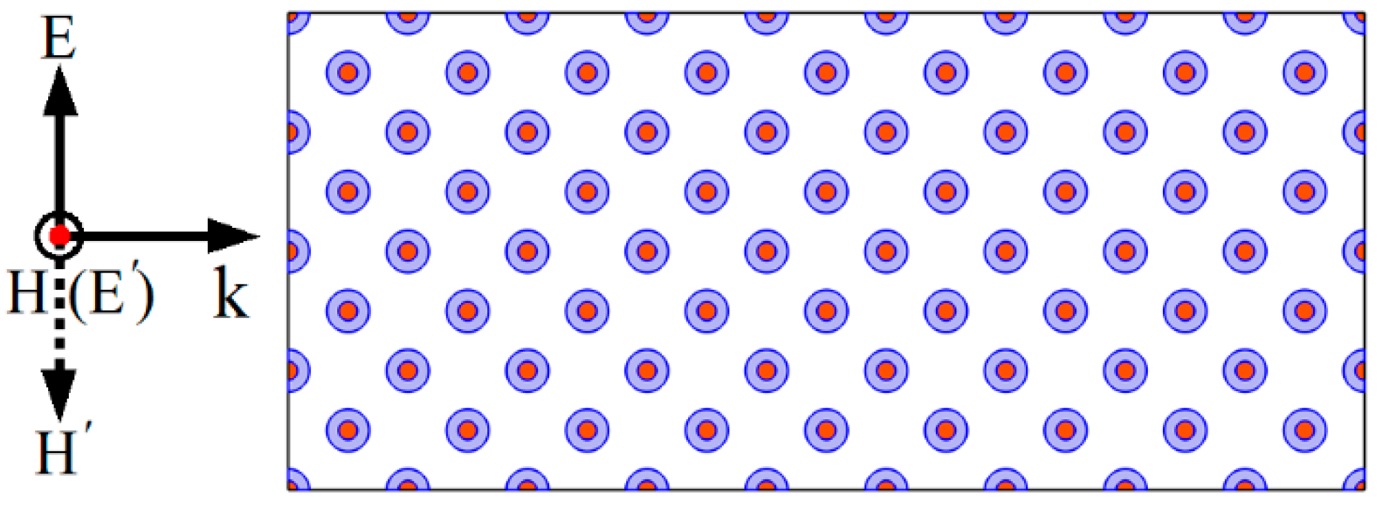
Abstract
:1. Introduction
2. Physical Model
3. Results and Discussion
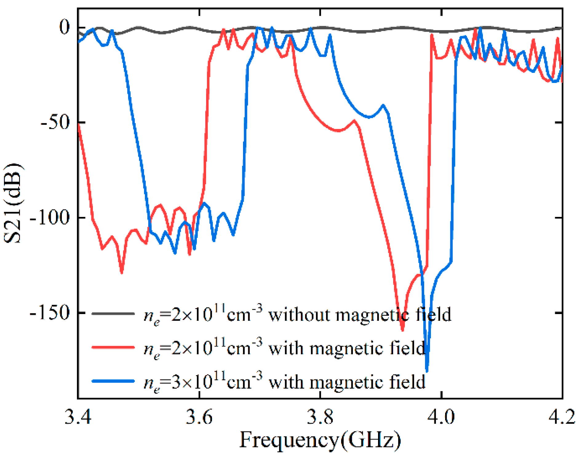
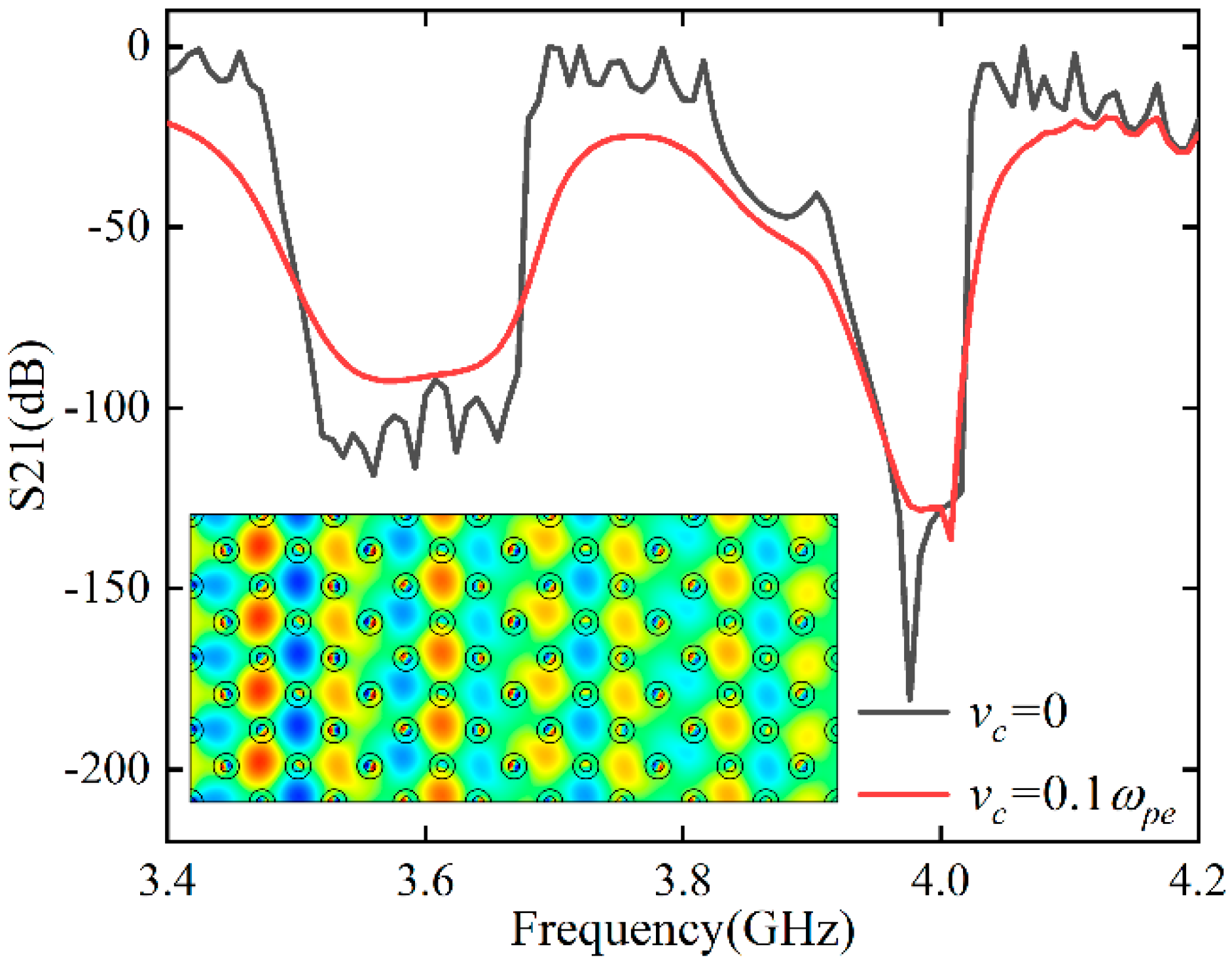
3.1. The Effect of Magnetic Field and Electron Density for the TM Polarization
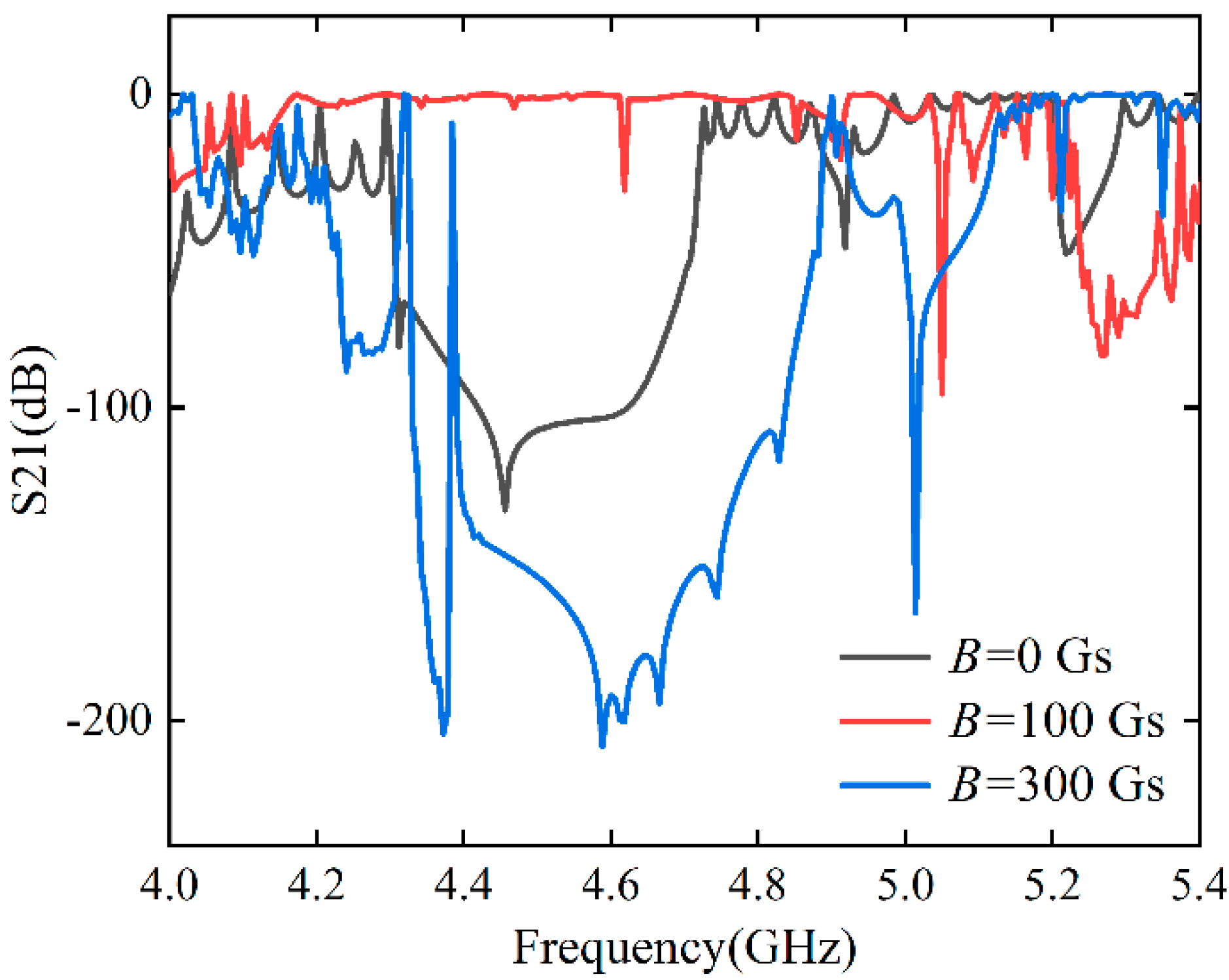
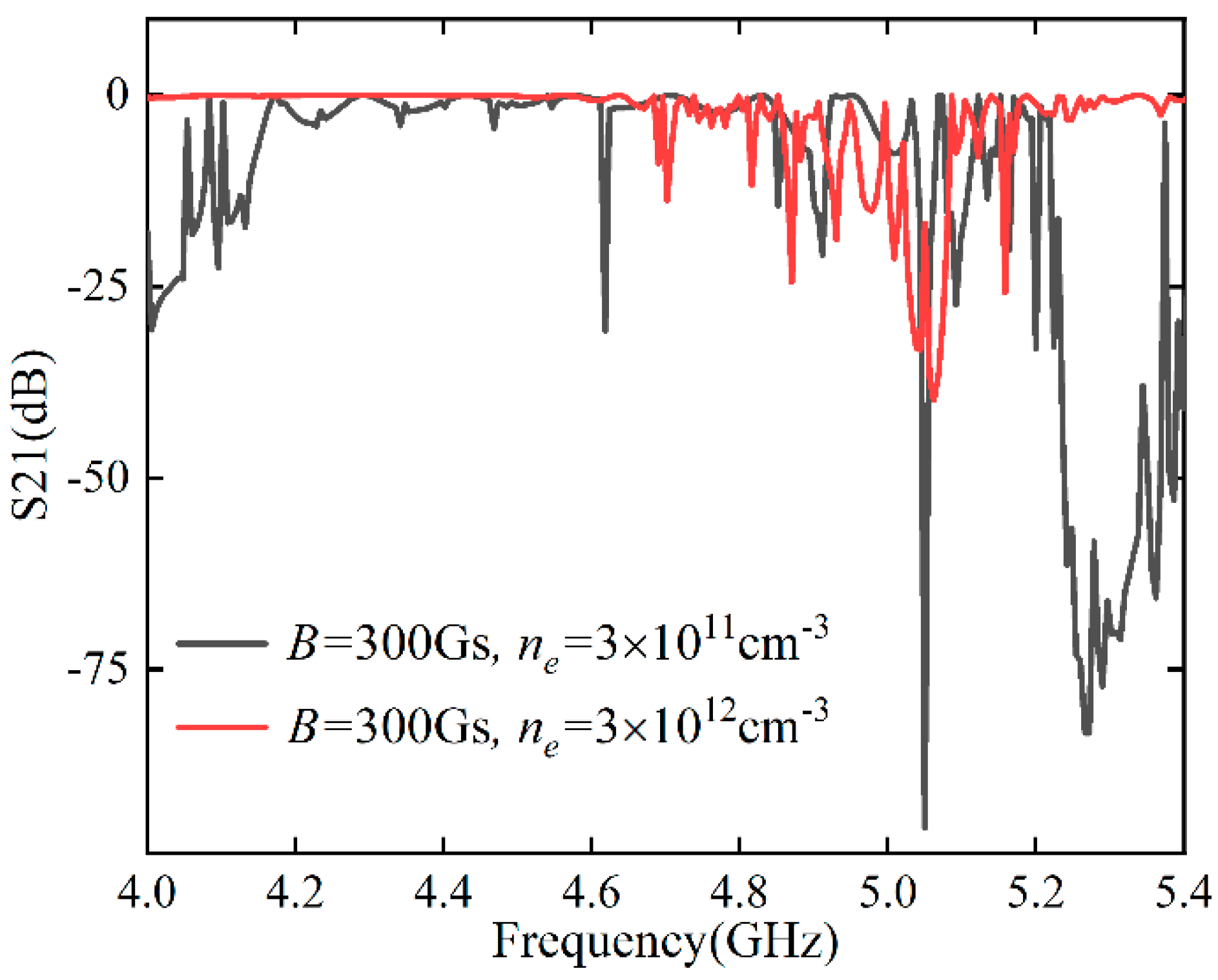
3.2. The Effect of Magnetic Field and Electron Density for the TE Polarization
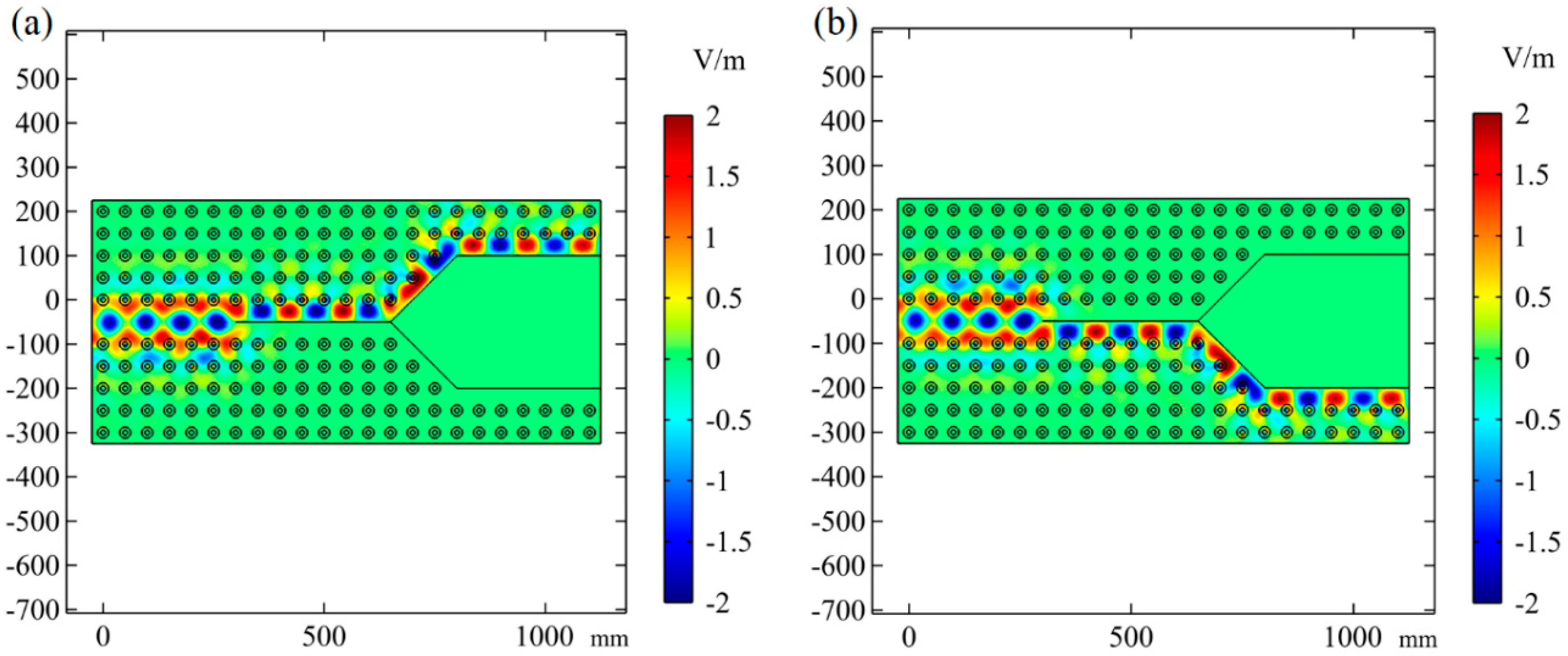
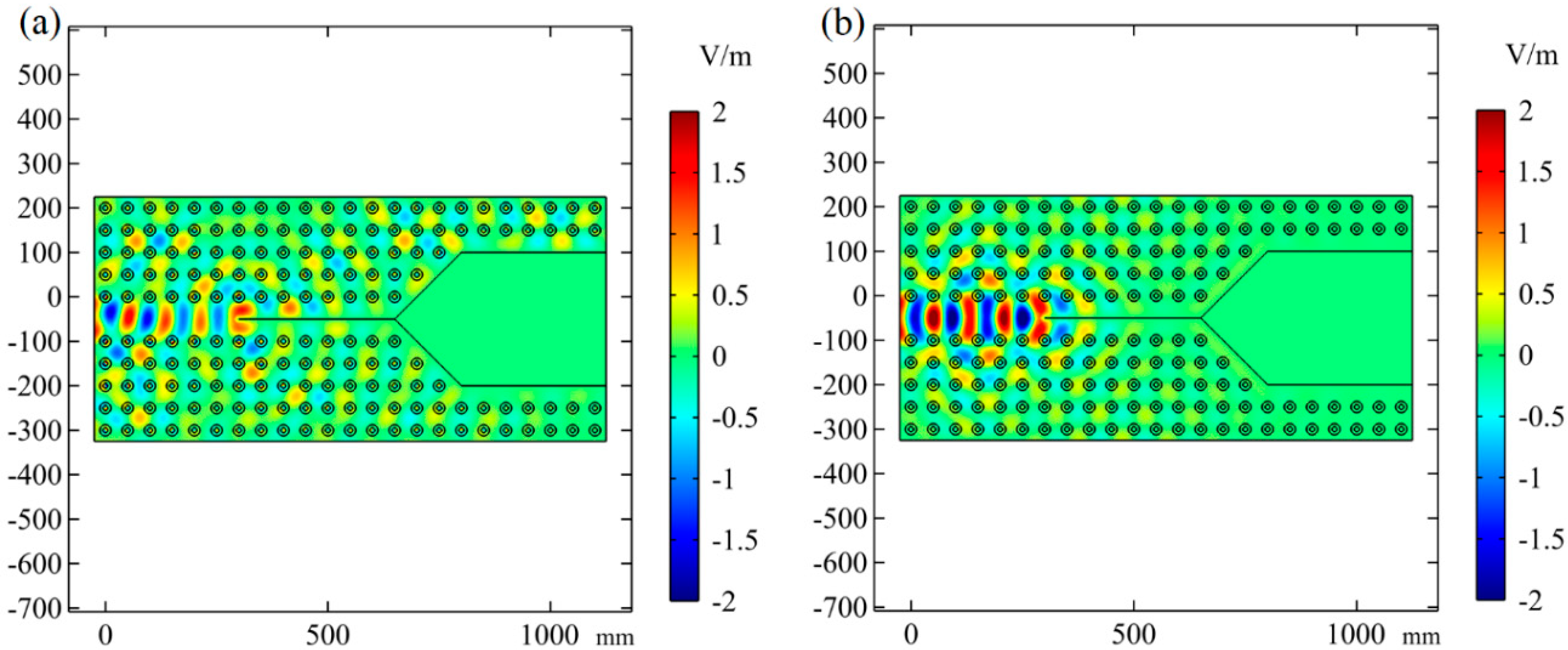
3.3. The Y-Shaped Tunable PPC Waveguide
4. Conclusions
Author Contributions
Funding
Institutional Review Board Statement
Informed Consent Statement
Data Availability Statement
Acknowledgments
Conflicts of Interest
References
- Yablonovitch, E. Inhibited Spontaneous Emission in Solid-State Physics and Electronics. Phys. Rev. Lett. 1987, 58, 2059. [Google Scholar] [CrossRef] [PubMed] [Green Version]
- John, S. Strong Localization of Photons in Certain Disordered Dielectric Super Lattices. Phys. Rev. Lett. 1987, 58, 2486–2489. [Google Scholar] [CrossRef] [PubMed] [Green Version]
- Kosaka, H.; Kawashima, T.; Tomita, A.; Notomi, M.; Tamamura, T.; Sato, T.; Kawakami, S. Superprism phenomena in photonic crystals. Phys. Rev. B 1998, 58, R10096. [Google Scholar] [CrossRef]
- Hu, X.; Chan, C.T. Photonic crystals with silver nanowires as a near-infrared superlens. Appl. Phys. Lett. 2004, 85, 1520–1522. [Google Scholar] [CrossRef]
- Xie, X.; Yan, S.; Dang, J.; Yang, J.; Xiao, S.; Wang, Y.; Shi, S.; Yang, L.; Dai, D.; Yuan, Y.; et al. Topological Cavity Based on Slow-Light Topological Edge Mode for Broadband Purcell Enhancement. Phys. Rev. Appl. 2021, 16, 014036. [Google Scholar] [CrossRef]
- Lu, L.; Joannopoulos, J.D.; Soljačić, M. Topological photonics. Nat. Photonics 2014, 8, 821–829. [Google Scholar] [CrossRef] [Green Version]
- Liu, G.; Wang, F.; Gao, Y.; Jia, B.; Guan, X.; Lu, P.; Song, H. Topology Optimization of Low-Loss Z-Bend 2D Photonic Crystal Waveguide. Photonics 2023, 10, 202. [Google Scholar] [CrossRef]
- He, C.; Chen, X.-L.; Lu, M.-H.; Li, X.-F.; Wan, W.-W.; Qian, X.-S.; Yin, R.-C.; Chen, Y.-F. Tunable one-way cross-waveguide splitter based on gyromagnetic photonic crystal. Appl. Phys. Lett. 2010, 96, 111111. [Google Scholar] [CrossRef]
- Le Thomas, N.; Zhang, H.; Jágerská, J.; Zabelin, V.; Houdré, R.; Sagnes, I.; Talneau, A. Light transport regimes in slow light photonic crystal waveguides. Phys. Rev. B 2009, 80, 125332. [Google Scholar] [CrossRef]
- Yu, Z.; Wang, Z.; Fan, S. One-way total reflection with one-dimensional magneto-optical photonic crystals. Appl. Phys. Lett. 2007, 90, 121133. [Google Scholar] [CrossRef]
- Wen, Y.; Liu, S.; Zhang, H.; Wang, L. The absorber realized by 2D photonic crystals with plasma constituents. J. Phys. Appl. Phys. 2018, 51, 025108. [Google Scholar] [CrossRef]
- Kamboj, G.K.; Yadav, R.P.; Kaler, R.S. Development of Reconfigurable Plasma Column Antenna. IEEE Trans. Plasma Sci. 2021, 49, 656–662. [Google Scholar] [CrossRef]
- Li, J.; Yao, J.; Yuan, C.; Wang, Y.; Zhou, Z.; Zhang, J. Tunable transmission near Dirac-like point in the designed plasma photonic crystal. Phys. Plasmas 2022, 29, 033505. [Google Scholar] [CrossRef]
- Liang, Y.; Liu, Z.; Peng, J.; Lin, L.; Lin, R.; Lin, Q. Study on Transmission Characteristics and Bandgap Types of Plasma Photonic Crystal. Photonics 2021, 8, 401. [Google Scholar] [CrossRef]
- Hojo, H.; Mase, A. Dispersion Relation of Electromagnetic Waves in One-Dimensional Plasma Photonic Crystals. J. Plasma Fusion Res. 2004, 80, 89–90. [Google Scholar] [CrossRef] [Green Version]
- Sakai, O.; Sakaguchi, T.; Ito, Y.; Tachibana, K. Interaction and control of millimetre-waves with microplasma arrays. Plasma Phys. Control. Fusion 2005, 47, B617–B627. [Google Scholar] [CrossRef]
- Sakai, O.; Sakaguchi, T.; Tachibana, K. Photonic bands in two-dimensional microplasma arrays. I. Theoretical derivation of band structures of electromagnetic waves. J. Appl. Phys. 2007, 101, 073304. [Google Scholar] [CrossRef]
- Iwai, A.; Righetti, F.; Wang, B.; Sakai, O.; Cappelli, M.A. A tunable double negative device consisting of a plasma array and a negative-permeability metamaterial. Phys. Plasmas 2020, 27, 023511. [Google Scholar] [CrossRef]
- Wang, B.; Rodríguez, J.A.; Miller, O.; Cappelli, M.A. Reconfigurable plasma-dielectric hybrid photonic crystal as a platform for electromagnetic wave manipulation and computing. Phys. Plasmas 2021, 28, 043502. [Google Scholar] [CrossRef]
- Fan, W.; Jia, M.; Zhu, P.; Liu, C.; Hou, X.; Zhang, J.; He, Y.; Liu, F. Realization of tunable plasma Lieb lattice in dielectric barrier discharges. APL Photonics 2022, 7, 116105. [Google Scholar] [CrossRef]
- Lin, M.; Fu, L.; Ahmed, S.; Wang, Q.; Zheng, Y.; Liang, Z.; Ouyang, Z. Polarization-Independent Circulator Based on Composite Rod of Ferrite and Plasma in Photonic Crystal Structure. Nanomaterials 2021, 11, 381. [Google Scholar] [CrossRef]
- Almawgani, A.H.M.; Alhamss, D.N.; Taya, S.A.; Colak, I.; Sharma, A.; Alhawari, A.R.H.; Patel, S.K. The properties of a tunable terahertz filter based on a photonic crystal with a magnetized plasma defect layer. Phys. Fluids 2022, 34, 082020. [Google Scholar] [CrossRef]
- Drude, P. Zur Elektronentheorie der Metalle. Ann. Phys. 1900, 306, 566–613. [Google Scholar] [CrossRef] [Green Version]
- Wu, S.; Chen, Y.; Liu, M.; Yang, L.; Zhang, C.; Liu, S. Numerical study on the modulation of THz wave propagation by collisional microplasma photonic crystal. Plasma Sci. Technol. 2020, 22, 115402. [Google Scholar] [CrossRef]
- Wang, B.; Cappelli, M.A. A plasma photonic crystal bandgap device. Appl. Phys. Lett. 2016, 108, 161101. [Google Scholar] [CrossRef]
- Wang, B.; Cappelli, M.A. A tunable microwave plasma photonic crystal filter. Appl. Phys. Lett. 2015, 107, 171107. [Google Scholar] [CrossRef]
- Howlader, M.K.; Yang, Y.; Roth, J.R. Time-resolved measurements of electron number density and collision frequency for a fluorescent lamp plasma using microwave diagnostics. IEEE Trans. Plasma Sci. 2005, 33, 1093–1099. [Google Scholar] [CrossRef]
- Li, J.; Zhou, C.; Yao, J.; Yuan, C.; Wang, Y.; Zhou, Z.; Zhang, J.; Kudryavtsev, A.A. Valley-dependent topological edge states in plasma photonic crystals. Plasma Sci. Technol. 2023, 25, 035001. [Google Scholar] [CrossRef]
- Guo, Z.; Long, Y.; Jiang, H.; Ren, J.; Chen, H. Anomalous unidirectional excitation of high-k hyperbolic modes using all-electric metasources. Adv. Photonics 2021, 3, 036001. [Google Scholar] [CrossRef]
- Houriez, L.S.; Mehrpour Bernety, H.; Rodríguez, J.A.; Wang, B.; Cappelli, M.A. Experimental study of electromagnetic wave scattering from a gyrotropic gaseous plasma column. Appl. Phys. Lett. 2022, 120, 223101. [Google Scholar] [CrossRef]
- Hu, S.; Song, J.; Guo, Z.; Jiang, H.; Deng, F.; Dong, L.; Chen, H. Omnidirectional nonreciprocal absorber realized by the magneto-optical hypercrystal. Opt. Express. 2022, 30, 12104–12119. [Google Scholar] [CrossRef] [PubMed]
- Wang, Z.; Chong, Y.D.; Joannopoulos, J.D.; Soljačić, M. Reflection-Free One-Way Edge Modes in a Gyromagnetic Photonic Crystal. Phys. Rev. Lett. 2008, 100, 013905. [Google Scholar] [CrossRef] [PubMed]


Disclaimer/Publisher’s Note: The statements, opinions and data contained in all publications are solely those of the individual author(s) and contributor(s) and not of MDPI and/or the editor(s). MDPI and/or the editor(s) disclaim responsibility for any injury to people or property resulting from any ideas, methods, instructions or products referred to in the content. |
© 2023 by the authors. Licensee MDPI, Basel, Switzerland. This article is an open access article distributed under the terms and conditions of the Creative Commons Attribution (CC BY) license (https://creativecommons.org/licenses/by/4.0/).
Share and Cite
Wang, H.; Li, J.; Guo, L.; Ma, D.; Yao, J.; Li, H.-P. Transmission Properties in Plasma Photonic Crystal Controlled by Magnetic Fields. Photonics 2023, 10, 333. https://doi.org/10.3390/photonics10030333
Wang H, Li J, Guo L, Ma D, Yao J, Li H-P. Transmission Properties in Plasma Photonic Crystal Controlled by Magnetic Fields. Photonics. 2023; 10(3):333. https://doi.org/10.3390/photonics10030333
Chicago/Turabian StyleWang, Hailu, Jianfei Li, Liang Guo, Dongliang Ma, Jingfeng Yao, and He-Ping Li. 2023. "Transmission Properties in Plasma Photonic Crystal Controlled by Magnetic Fields" Photonics 10, no. 3: 333. https://doi.org/10.3390/photonics10030333