1. Introduction
The generation of OAM modes using fiber systems has a long and rich history [
1]. Fiber systems show interesting and significant advantages for the generation of OAM modes compared to spatial methods for generating OAM beams such as miniaturization and low insertion losses. Among the devices that allow the generation of OAM modes in fiber systems, four main types can be distinguished, namely, optical fiber gratings [
2], mode selective couplers [
3], micro-structured optical fibers [
4], and photonic lanterns [
5]. The principle of operation of these devices can be reduced to the following sequence: first, coupling between the fundamental core mode and high-order modes, and second, adjusting four degenerate modes in one high-order mode and obtaining the OAM mode through combinations of amplitudes and phases among these degenerate modes [
1]. In this paper, we will focus on OAM resonances in NCHCFs. The generation of OAM modes in hollow-core micro-structured fibers has already been carried out in [
6,
7]. In the first case, terahertz OAM modes were generated and transmitted in the flexible twisted hollow-core anti-resonant fiber, and in the second case, the transmission of OAM modes in anti-resonant hollow-core fiber in an all-fiber system was demonstrated. In addition, interesting work on the transmission of fractional topological charges [
8] via circular arrays of anisotropic fiber [
9], as well as work on super bursts of the orbital angular momentum in astigmatic invariant structured beams [
10], should be noted.
It is known that the total angular momentum of a light beam propagating in isotropic medium can be divided into external orbital angular momentum (EOAM), internal orbital angular momentum (IOAM), and spin angular momentum (SAM) [
11]. The first is related to the angular momentum of a beam with respect to the external frame and the second is related to the frame connected with the ‘gravity point’ of a beam. Spin angular momentum is related to the polarization of a light beam. The separation of the orbital angular momentum of a light beam into internal and external parts was first demonstrated numerically and experimentally in [
12]. The angular momentum independent of the axis choice is intrinsic. The OAM of light beams in the propagation direction has a discrete value of
per photon, where
is an integer. OAM beams have a phase dislocation on the beam axis and OAM carried by the phase singularity along the axis of the beam is intrinsic. In this case, it is worth noting, as stated in work [
12], that the light beam OAM is intrinsic provided the direction of the axis is chosen in such a way that the transverse momentum is zero. It is clear that any light beam apertured symmetrically about the beam axis satisfies this condition and has zero transverse momentum. In this case, the OAM of the beam can be described as intrinsic, but the transverse momentum is nonzero when the beam passes through an off-axis aperture. In this case, the OAM of the beam depends on the choice of a calculation axis and can be described as extrinsic. The SAM of a light beam is always intrinsic and arises due to light polarization. It is given by
per photon, where
corresponds to pure circular polarization. The reasoning given above for the light beam can also be applied to the modes of leaky fibers. In this case, there is always a transverse momentum of the core mode energy [
13] and, therefore, the leaky modes can have an extrinsic OAM under bending.
In this paper, we demonstrate the possibility of a resonant increase in OAM of coupled modes in hollow-core fibers with a cladding consisting of six capillaries and a real NCHCF with the same number of cladding capillaries when a bend is applied to them. It is known that in such fibers there is an interaction between the core and cladding modes [
14]. Cladding modes can exist both in the cladding capillary walls and in their cavities. Coupling between the air core mode and the cladding modes can arise due to the perturbation of the transverse distribution of the refractive index of the fiber cross section under bending [
15] or occurs at the edge of the transmission band. There are two types of coupling between the core and cladding modes, namely, anti-crossing (avoided crossing) and crossing [
16,
17]. The difference between crossing and anti-crossing lies in the fact the crossing can be considered as an accidental coincidence of the effective refractive indices of two modes. In the case of anti-crossing, the modes exchange their roles and their effective refractive indices diverge.
Therefore, here we demonstrate that crossing and anti-crossing between the fundamental air core mode and cladding modes occurring under bending lead to different behaviors of OAM of these modes. In [
18], it was shown that an increase in OAM at the transmission band edge arises from the spin–orbital interaction, which occurs at the core-cladding boundary at the anti-crossing between the circular polarized fundamental air core mode and the cladding modes. In the case of a fiber bend, as calculations show, a resonant increase in the OAM arises from the crossing that occurs between the linearly polarized fundamental air core mode and the cladding modes having different optical losses. It will be shown that OAM increases by a small amount in the presence of anti-crossing between the fundamental air core mode and modes of the cladding capillary cavity under bending.
2. OAM for Linear Polarized Fundamental Air Core Modes of NCHCF
Let us consider straight silica glass NCHCFs with six cladding capillaries and with an air core diameter
D = 21 µm. The cladding capillary inner diameter is
d = 16 µm and the cladding capillary wall thickness is
t = 0.71 µm. This wall thickness is chosen so that the minimum leakage loss is around a wavelength of 1 µm. We consider two NCHCFs, one with a supporting tube (when the cladding capillaries are located on a thick glass tube) and one without a supporting tube. The leakage loss dependence and the real part of the effective refractive index on the wavelength for the linearly polarized fundamental air core modes of these fibers are shown in
Figure 1.
Assuming a harmonic time dependence for the electric and magnetic fields, the air core modes are considered to propagate in the
z-direction:
where
is a propagation constant of the air core mode and
is a circle frequency. The time average value of the Poynting vector of the fundamental air core mode is
and its kinetic (Abraham-type)
z-component of angular momentum density is
, where
is an azimuthal component of the Poynting vector. In order to calculate an angular momentum (linear density along the
z-axis), it is necessary to calculate the integral
.
It is known that the Poynting vector of the air core mode vector can be decomposed into orbital and spin parts in terms of
(total electric field of the air core mode) [
19]:
where
c is the velocity of light and
is the vacuum permittivity. Thus, it is possible to calculate the spin and orbital parts of the
z-component of the angular momentum density for the air core mode.
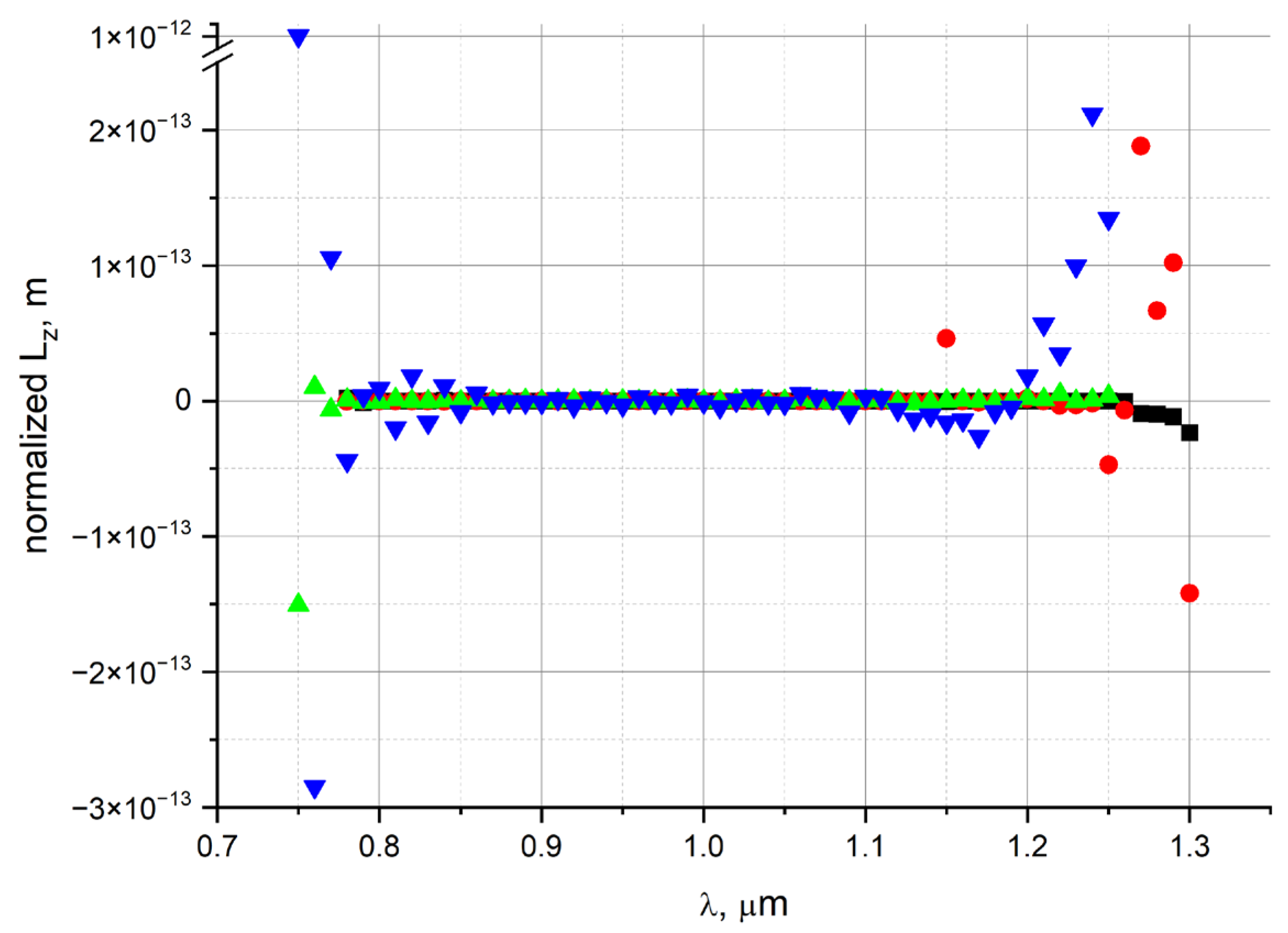
Let us calculate the spin and orbital parts of the angular momentum density for the linearly polarized fundamental air core modes of NCHCFs described above (
Figure 1) in the same transmission band. The dependences of these parts of the angular momentum on the wavelength are shown in
Figure 2. The linearly polarized mode is constructed as a weighted sum of two fundamental modes in such a way that the electric field of the mode at the origin (0, 0) maintains its direction. This is possible due to an equality of effective refractive indices of the fundamental air core modes of NCHCF.
As can be seen from
Figure 2, even for linearly polarized fundamental air core modes, the resonant values of the orbital part of the angular momentum density are observed at the edges of the transmission band. In order to give an explanation for this effect, let us consider the perturbed refractive index of the cross section of NCHCFs caused by its bending.
3. OAM for Linearly Polarized Fundamental Air Core Mode when NCHCF Is Bent
In this section, we discuss the NCHCFs considered in
Section 2 under bending and calculate the corresponding OAM of the fundamental air core modes. We assume that the bend is applied along the x-axis, and then the change in the refractive index in the cross section of the fiber can be described as [
15]:
where
n(
x,
y) is a refractive index of the fiber cross section and
is a bend radius.
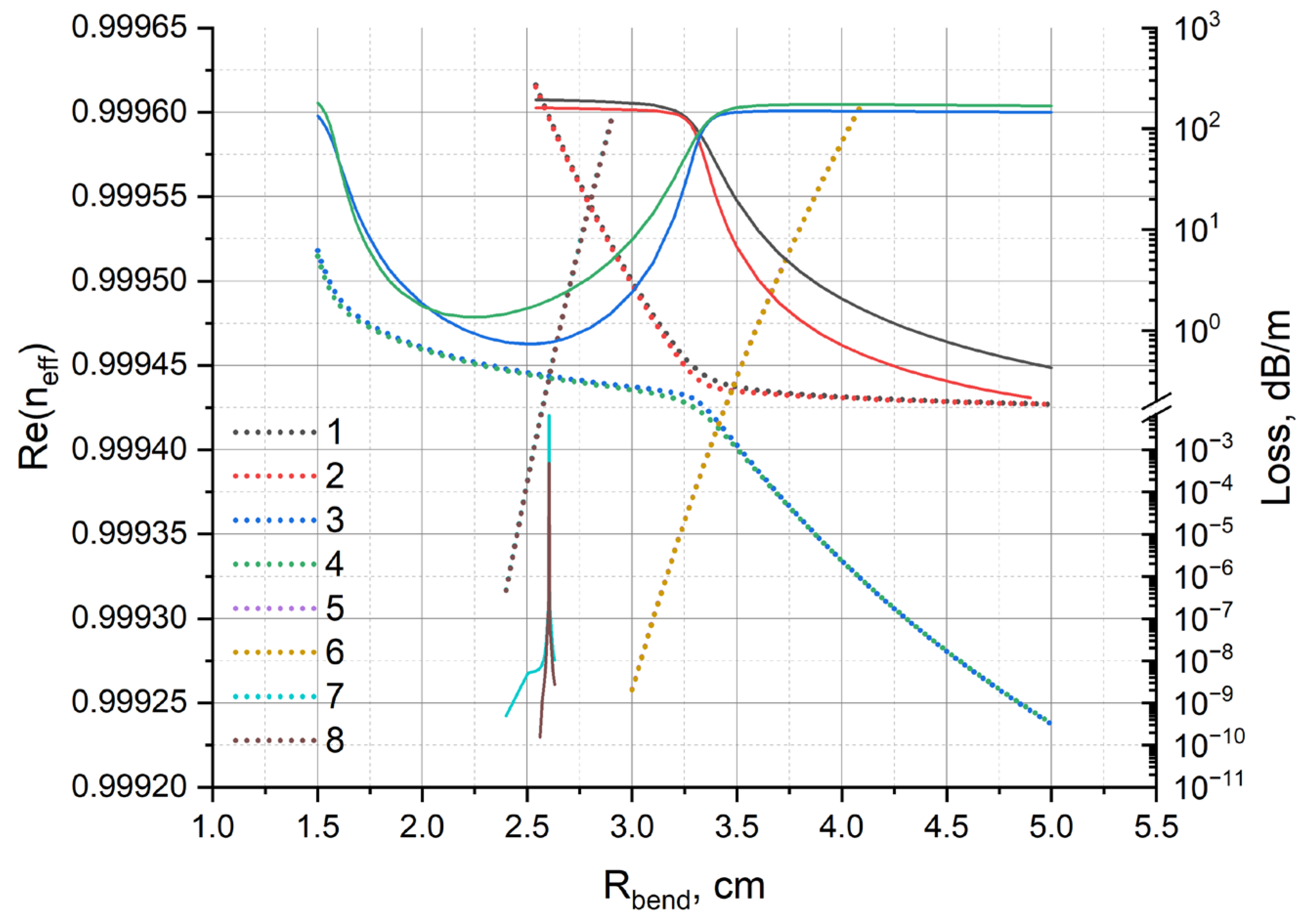
The loss dependence and the real part of the effective index on the bend radius for the linear polarized fundamental air core modes and the cladding modes for NCHCF without a supporting tube are shown in
Figure 3. As can be seen from
Figure 3, there is both anti-crossing between the fundamental air core mode and the cladding mode (bend radius is 3.25 cm) as well as two crossings in this range of values of the bend radius (bend radii are 2.5 cm and 3.4 cm, respectively).
The distribution of the axial component of the Poynting vector for two cladding modes (
Figure 3) at anti-crossing (1, 2, 3, 4) and crossing (3, 4, 7, 8) are shown in
Figure 4.
As can be seen from
Figure 4, there is a strong coupling between the fundamental air core mode of NCHCF without a supporting tube and the cladding capillary modes both at the anti-crossing point and at the crossing points.
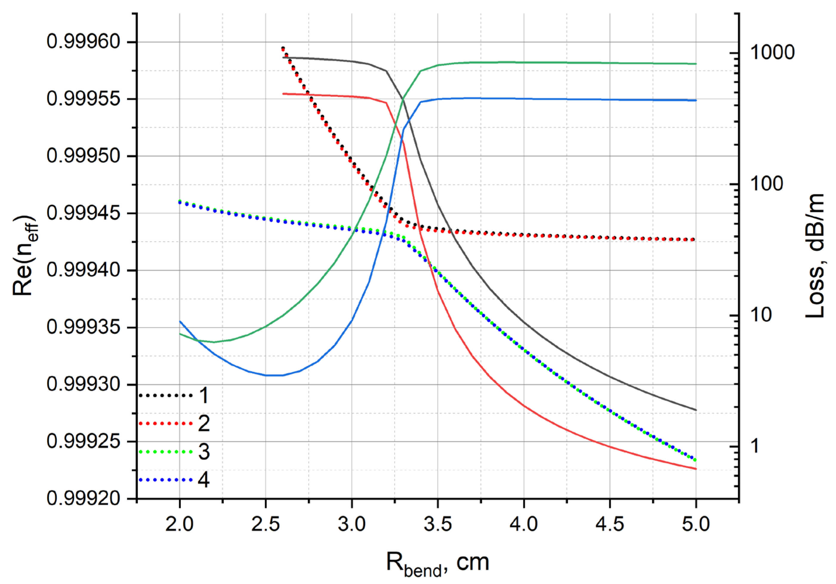
Let us calculate the same dependencies as in
Figure 3 for NCHCF with a supporting tube. They are shown in
Figure 5.
It can be seen from
Figure 5 that in the case of NCHCF with a supporting tube, there is only anti-crossing between the fundamental air core mode and the cladding capillary mode that is formed in the air core of the cladding capillary (
Figure 4, top left figure). Crossing does not occur in the given range of the bend radius. In this case, the mode of the cladding capillary wall is suppressed due to the influence of a supporting tube.
If we calculate OAM for each mode with the dispersion dependences shown in
Figure 3, then we can obtain a system of resonances, as shown in
Figure 6.
These high-amplitude resonances occur at one crossing point at a bend radius of ~2.6 cm. There are also the same type of resonances at a bend radius of ~3.5 cm, but their magnitude is much lower. No resonances are observed at the anti-crossing points either for NCHCF with a supporting tube or for NCHCF without a supporting tube. This most likely indicates that in order to obtain OAM resonances in leaky fibers when they are bent, it is necessary to have a coupling (crossing) between the fundamental core mode and the cladding mode, which has very different losses from those of the fundamental mode.
4. Discussion
We have analyzed the behavior of the OAM arising from crossing and anti-crossing between the core and the cladding modes of NCHCF with and without a supporting tube, focusing on the air core mode with a linear polarization. In this case, the spin part of the angular momentum of the fundamental air core mode was close to zero. However, some OAM resonances were observed at the edge of the transmission band for straight NCHCFs with and without a supporting tube. They were associated with the presence of coupling between the fundamental air core mode and the cladding modes. The change in the values of spin angular momentum was associated with the appearance of an elliptical polarization of the fundamental air core mode near the core-cladding boundary. In this case, a spin–orbital interaction arises, which leads to a deviation of the polarization of the fundamental air core mode from the linear polarization at the core-cladding boundary.
When the NCHCF is bent, the fundamental air core mode also has a linear polarization. In this case, anti-crossing with cavity modes of the cladding capillaries and crossing with the modes of the cladding capillary wall can arise. For the NCHCF with a supporting tube, the crossing does not occur due to mode composition perturbations arising from the tube. The difference between crossing and anti-crossing lies in the fact that in the first case, the interacting modes have the same real parts of the effective refractive indices and in the second case, the imaginary parts are also close in value.
The resonant growth of OAM most likely cannot be explained by means of EOAM since while at anti-crossing point, there is a significant change in the position of the “center of mass” of the mode (
Figure 4, top right), the increase in the OAM is much smaller than in the case of the crossing between the fundamental mode and the mode of the capillary wall.
The complex interaction of energy fluxes of the fundamental air core mode and certain cladding modes with significantly different losses at the presence of crossing leads to a corresponding increase in the OAM.
This kind of resonant phenomenon associated with OAM may also be observed in other waveguide systems. For example, this kind of resonant growth of OAM can be found in all-solid micro-structured fibers [
20] if a crossing between two interacting modes with a significant loss difference is obtained. In our future work, we will be conducting a search for such new waveguide systems with OAM-resonant properties. In conclusion, it should be noted that the OAM resonances described in this work can possibly serve as a new method for generating OAM modes in optical fibers and nanophotonic devices.


