Communication

Suppression of Nonlinear Optical Effects in DWDM-PON by Frequency Modulation Non-Coherent Detection

School of Information Science and Engineering, Shandong University, Qingdao 266237, China
*
Authors to whom correspondence should be addressed.
Photonics 2023, 10(3), 323; https://doi.org/10.3390/photonics10030323
Submission received: 16 February 2023 / Revised: 12 March 2023 / Accepted: 13 March 2023 / Published: 17 March 2023
(This article belongs to the Special Issue Optical Fiber Transmission Systems)

Abstract

:
We propose a simple and cost-effective method, using a direct frequency modulation (FM) and noncoherent detection (NCD) scheme, to suppress the nonlinear optical effects in dense wavelength division multiplexed (DWDM) optical communication. The FM transmitter comprises a directly modulated distributed feedback laser and a saturable semiconductor optical amplifier. In the NCD receiver, an optical slope filter as the FM to intensity modulation (IM) signal convertor is placed before a conventional photodetector. Because the FM signal has more evenly distributed optical power, bit-pattern-dependent nonlinear effects are consequently suppressed. After analyzing the nonlinear effects in the FM-NCD system and traditional IM direct detection (IM-DD) system, we found that the minimum achievable BER of the proposed FM-NCD scheme is 40 dB smaller. Moreover, a 2 Tbps (10 Gb/s × 200 channels) capacity was achieved by the FM-NCD system in 100 km DWDM passive optical networks (PONs), which is twice the capacity of the IM-DD system (10 Gb/s × 100 channels) under the same condition. These results indicate that WDM-PONs with the cost-effective FM-NCD scheme are strong candidates for future broad access networks and show great potential for the combination of optical access and metro networks for future generations of PONs.

1. Introduction

The explosive growth in consumer and business applications, such as high-quality video conferencing, ultra-high-definition television, and ubiquitous cloud computing, has led to demands for larger bandwidth in optical access networks [1]. Despite the emergence of 10 Gb/s capable passive optical networks (PONs) based on the time division multiplexed (TDM) [2,3], further enhancements in the bit rates of TDM-PON are extremely challenging because of the limitations imposed by high-speed electronics [1]. Thus, introducing wavelength division multiplexing (WDM) into PON has attracted widespread attention and has been extensively investigated [4,5,6,7,8,9]. For example, the time- and wavelength-division multiplexed PON (TWDM-PON) architectures have already been recommended as the next-generation passive optical network stage 2 (NGPON2) in the ITU-T G.989.1 standard [5]. Research is now taking new steps and aiming at realizing long-reach dense wavelength division multiplexed PONs (DWDM-PON) [8,9]. Due to the advantages of higher bandwidth, easier upgradability, and better security, WDM-PONs are considered strong candidates for future broad access networks and the trend in access network development [1,4].
On the other hand, the simultaneous transmission of multiple wavelength channels inside a single fiber gives rise to fiber nonlinear effects, which include self-phase modulation (SPM); cross-phase modulation (XPM); four-wave mixing (FWM), induced by the intensity dependence of the refractive index; and the nonlinear effects caused by stimulated inelastic scattering, such as stimulated Raman scattering (SRS) and stimulated Brillouin scattering (SBS) [10,11]. These nonlinear effects result in inter- and intrachannel crosstalk, which seriously jeopardize system performance. Numerous techniques have been proposed to manage nonlinear effects [12,13,14]. A method suggested in [12] to lessen XPM is reducing the overlap time of “1” bit in neighboring channels by adding relative time delays among the WDM wavelength channels. Raman crosstalk can be effectively suppressed by the midway spectral inversion technique [13]. Nonlinearity impairments can also be compensated in the digital signal processing core of optical receivers with the virtual backpropagation method [14]. However, the implementation of these solutions is generally complicated and not appropriate for cost-sensitive PON systems.
In this paper, we propose a frequency modulation (FM) noncoherent detection (NCD) scheme, aiming at cost-effectively suppressing nonlinear effects. The FM signal can be easily obtained by the parasitic chirp in a directly modulated distributed feedback (DFB) laser, whose output power fluctuation is eliminated with a saturable semiconductor optical amplifier (SOA). In the NCD receiver, an optical slope filter converts the FM signal to an intensity modulation (IM) signal, which is subsequently detected by a conventional photodetector. Due to the evenly distributed and low peak optical power of FM signals, bit-pattern-dependent nonlinear effects are reduced. In our work, the performance of this scheme was numerically simulated and demonstrated. Compared with the traditional IM-DD system, applying this FM-NCD scheme in DWDM-PONs can increase system tolerance against fiber nonlinearity in a cost-effective manner and lead to considerable performance improvements, i.e., it extremely lowers the minimum achievable BER and doubles the maximum system capacity, which also shows great potential in the combination of optical access and metro networks for the future generations of PONs.

2. System Configuration and Simulation Model

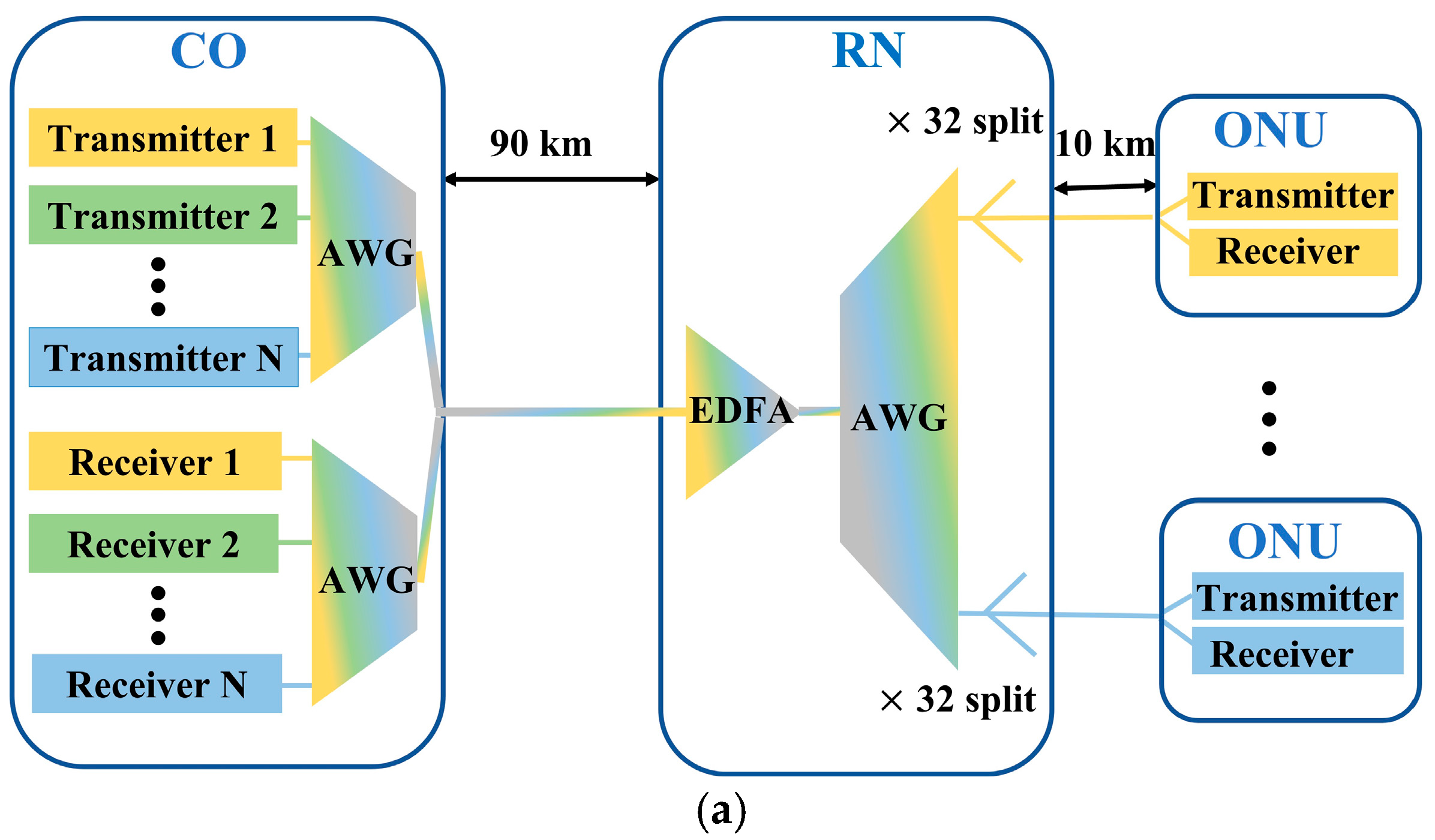
2.1. System Configuration

The antinonlinearity of the proposed FM-NCD system is demonstrated in the long-reach DWDM-PON, whose schematic diagram is sketched in Figure 1a. The optical line terminal (OLT) located in the central office (CO) transmits/receives DWDM optical signals toward/from the remote node (RN) via one feeder fiber. In the RN, the erbium-doped fiber amplifier (EDFA), as a reach extender, offers power compensation. Additionally, an arrayed waveguide grating (AWG), as a multiplexer/demultiplexer, routes different wavelength channels toward/from user-dedicated optical network units (ONUs) through drop fibers. By utilizing a 1:32 splitter/combiner with TDM and time division multiple access (TDMA), each wavelength channel is shared by 32 ONUs.
For the proposed FM-NCD scheme applied in this system, the transmitted FM optical signal is generated as shown in Figure 1b. Due to the carrier-induced changes in the mode index, the intensity modulation in semiconductor lasers is accompanied by parasitic frequency modulation. Therefore, an IM-FM optical signal is obtained by a directly modulated DFB laser. The amplitude of this IM-FM signal is then saturated to nearly constant by an inline SOA with saturable amplification. Thus, a comparatively pure FM optical signal is obtained. Importantly, this FM optical signal is detected by a cost-effective NCD receiver (depicted in Figure 1c), rather than the conventional coherent detection scheme, [15]. By exploiting an optical slope filter, the FM signal is transformed into an IM signal which can be detected by a conventional direct detection receiver. Moreover, the falling tail, instead of the leading tail of the optical slope filter, is employed because the chirp fluctuation of the FM signal at high frequencies is larger than that at low frequencies.
For comparison, a conventional IM-DD system configuration is also given in Figure 1b′,c′. The differences between the two system configurations are obvious. An additional slope filter in the receiver of the FM-NCD system is needed, but the expensive amplitude modulator in the transmitter of the IM-DD system is replaced by a cheaper SOA in the FM-NCD system. Therefore, the proposed FM-NCD system does not add much to the system cost.

2.2. Simulation Model

The operating wavelengths of the long-reach DWDM-PON are in the C band. Here we took 1550 nm as an example to elaborate simulation models of the optical transmitter, optical fiber, and optical receiver.

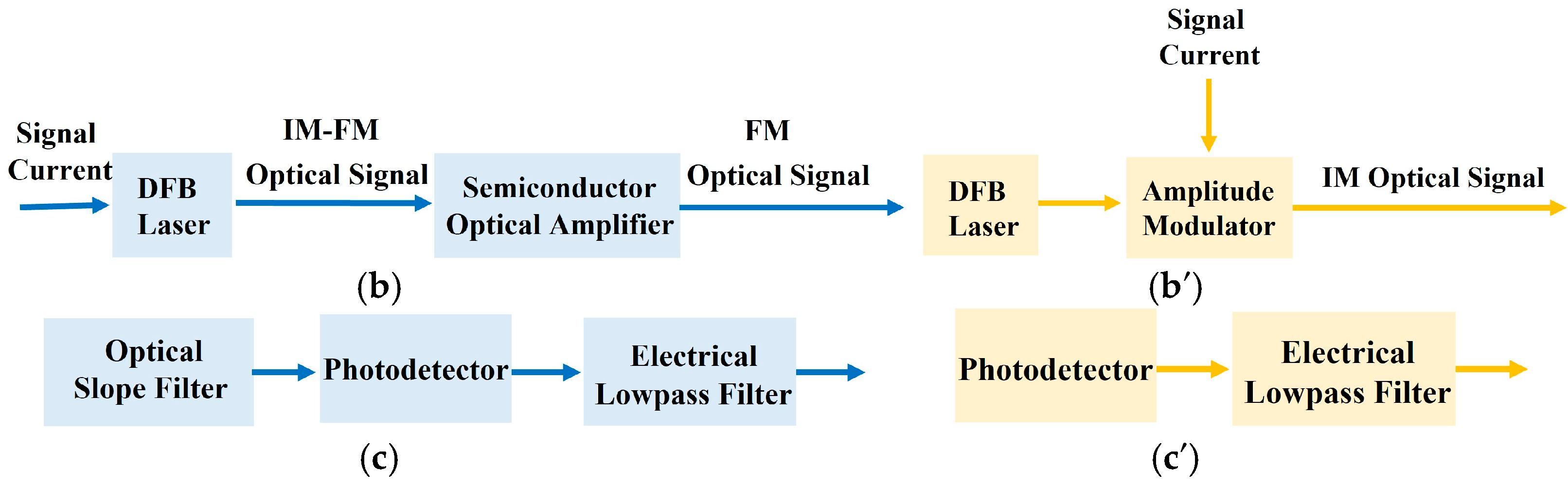
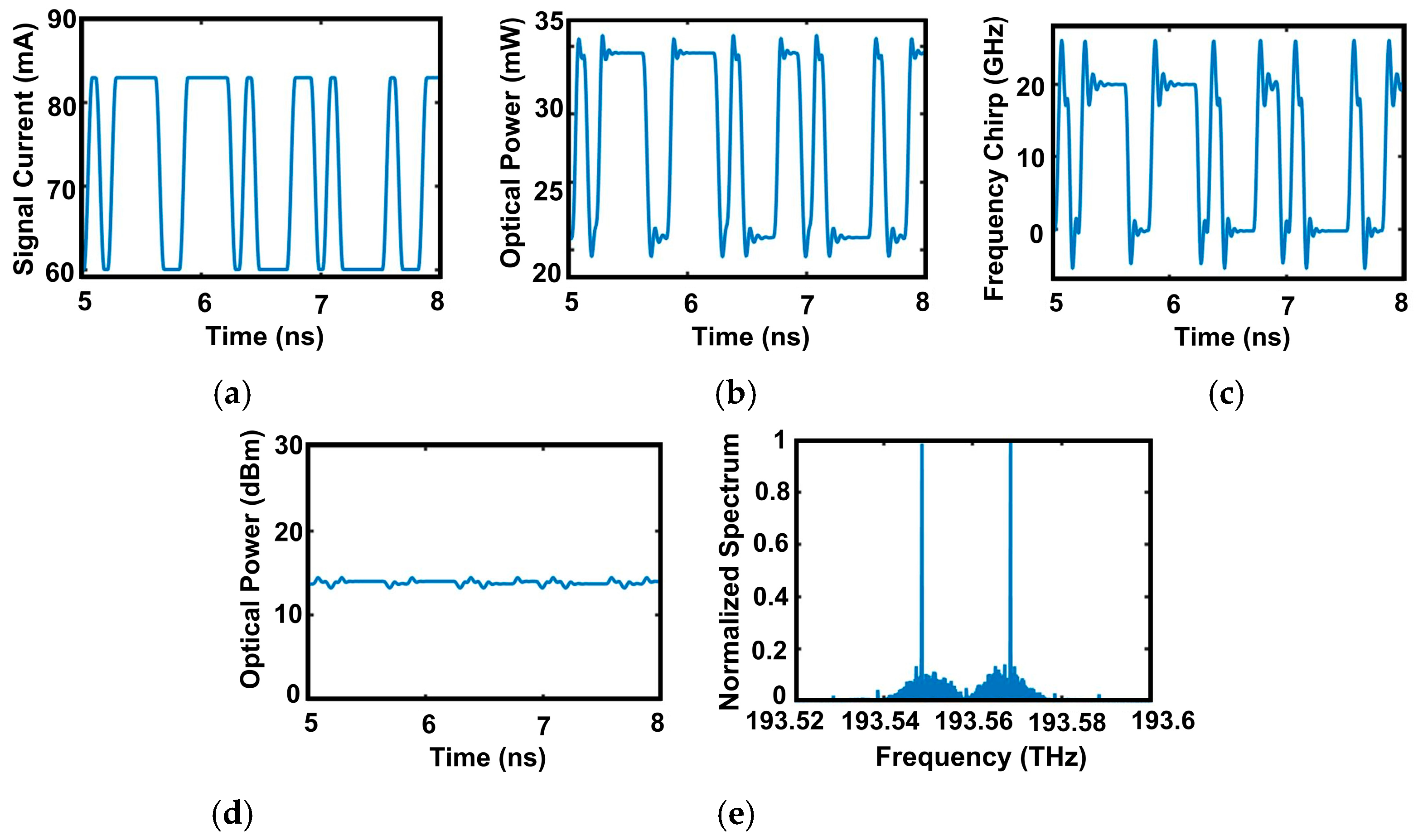
2.2.1. Optical Transmitter

To model the transmitter, the DFB laser was described by a self-consistent one-dimensional (along the cavity direction) traveling wave model [16,17], with all governing equations provided in the Supplementary Material. Its characteristics under 10 Gbps direct modulation were simulated with parameters given in Table 1. As shown in Figure 2b, the output optical power is modulated by the applied signal current, as in Figure 2a. It should be noted that due to the parasitic FM effect, the frequency chirp of the DFB laser also varies with time in a manner similar to the applied signal current, and the result is exhibited in Figure 2c. To obtain a pure FM signal, a SOA operated in its saturation mode is needed to suppress the power fluctuation of the IM-FM signal. The effects of the saturable SOA on optical power and phase of the input signals were calculated by exploiting a physics-based model [16,17,18], given in the Supplementary Material, with its parameters summarized in Table 2. The output optical power of the saturable SOA, as exhibited in Figure 2d, has just minor fluctuations and is saturated by the SOA. The spectrum of optical signal passing through the saturable SOA, as shown in Figure 2e, has two main lasing frequencies, which represent symbol 0 (left one) and symbol 1 (right one). Therefore, the output of the saturable SOA is a relatively pure FM signal.
Different from the proposed FM-NCD system, the transmitter in the IM-DD system is composed of a DFB laser under CW operation and an amplitude modulator. It loads information through external modulation. In our simulation, this amplitude modulator was assumed to be ideal. The operating condition of the transmitter in the IM-DD system was chosen as follows: (i) the output average optical power was the same as that of the FM-NCD system, and (ii) the extinction ratio satisfied the ITU standard for TWDM-PON [5].

2.2.2. Fiber-Optic Channel

The evolution of a propagating pulse inside the single-mode fiber is governed by the nonlinear Schrodinger equation (NSE) [19], given as follows:
A n z + 1 v g n A n t + i β 2 n 2 2 A n t 2 i β 3 n 6 3 A n t 3 + α 2 A n = i γ n [ | A n | 2 + 2 m n | A m | 2 ] A n + ( g Δ f 2 A e f f ) m = 1 N ( m n ) | A m | 2 A n ,
where the subscripts  n  and  m  are assigned to corresponding variables in the  n th  and  m th  wavelength channels, respectively. The total number of wavelength channels is assumed to be  N A n  or  A m  is the low-varying envelope of the optical field;  v g n  is the group velocity;  β 2 n  and  β 3 n  are the second- and third-order dispersions, respectively;  α  is fiber loss;  γ n = 2 π n ¯ 2 / ( A e f f λ n )  is the fiber nonlinear parameter;  n ¯ 2  is the nonlinear index coefficient;  A e f f  is the effective cross-sectional area of the single-mode fiber;  λ n  is the wavelength;  g  is the slope of the Raman gain profile;  Δ f  is the interchannel frequency spacing;  i  is the imaginary unit. The first term on the right side of this equation represents the effects of SPM and XPM. Additionally, the influence of the SRS is included by the second term on the right side of this equation, where the gain is divided into two to account for polarization averaging. Here, FWM and SBS are ignored, because the dispersion parameter is large enough to suppress FWM, and SBS does not produce interchannel crosstalk in WDM systems because the 11 GHz frequency shift is much smaller than the typical channel spacing [11]. However, the SBS limits the channel power. We can suppress the SBS effect with considerable effort to increase the SBS threshold [20,21,22]. Therefore, the impact of SBS was not of concern in this study.
In our system configuration, the G.655 nonzero dispersion-shifted single-mode fiber (NZDSF) at a length of 90 km was adopted as the feeder fiber for reducing the dispersion and reaching the objective long distance. As the legacy drop fibers in existing PONs, G.652 standard single mode fibers (SMFs) with a length of 10 km are recommended to be reused in the long-reach DWDM-PONs for saving deployment expenses. With the parameters of the two varieties of fibers summarized in Table 3, the NSE can be solved by the split-step method [23,24]. The step size along the propagation direction in this method affects the simulation error. It must be shorter than the smallest of the lengths, including the second-order dispersion length  L D 2 , the third-order dispersion length  L D 3 , and the nonlinear length  L N L  [19,25]. These lengths are defined as:
    L D 2 = T 0 2 β 2 ,      
L D 3 = T 0 3 β 3 ,
L N L = 1 γ e α z P ,
where  T 0  indicates the input pulse width, and  P  is the peak power of the incident pulse. The step size in our simulation was chosen as 0.2 km to satisfy the requirements.

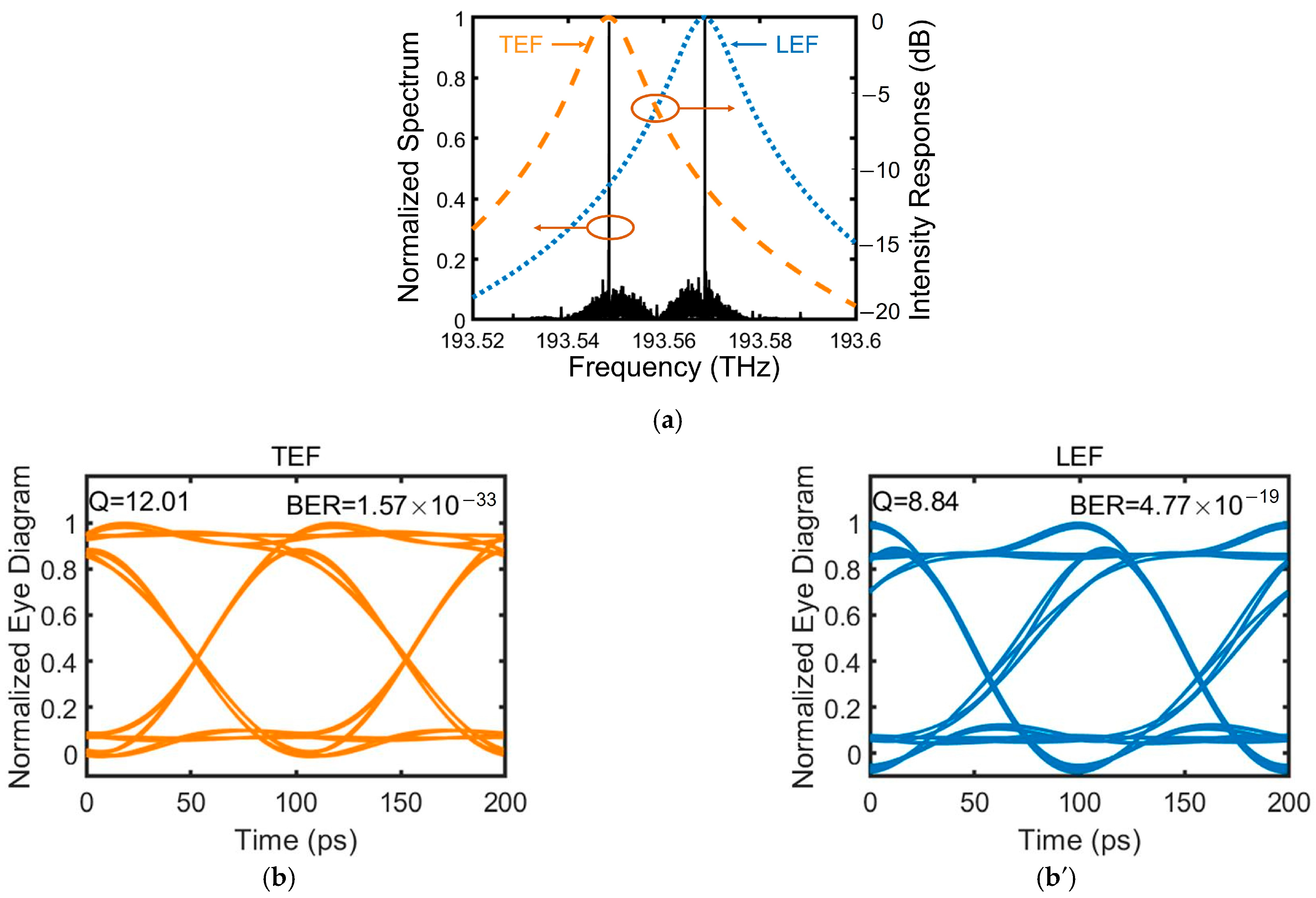
2.2.3. Optical Receiver

In the optical receiver of the FM-NCD system, the optical slope filter has the crucial function of converting the FM signal back to an IM signal for noncoherent detection purpose. Without loss of much generality, we considered a second-order optical bandpass filter expressed by:
H s l ( j ω ) = A j ω ω d / [ ( j ω ) 2 + j ω ω d + ω 0 2 ] ,
which can be practically achieved through, for example, multiple dielectric layer coatings. We obtained the required optical slope filtering function by choosing the rising or falling tail of its frequency response, i.e., the leading-edge filter (LEF) or the tailing-edge filter (TEF). As shown in Figure 3a, the LEF and TEF suppress the low- and high-frequency band of the FM optical signal, respectively. Here, the LEF and TEF are tuned at  ω 0 = 1.2162 × 10 15  rad/s and  ω 0 = 1.2161 × 10 15  rad/s, respectively, with a common set for  A = 1  and  ω d = 7.2552 × 10 10  rad/s. The chirp fluctuation of the FM signal at high frequencies is more severe than at low frequencies, which consequently causes the power fluctuation of the transformed IM signal through the LEF to be larger than that through the TEF. The TEF thereby is superior to the LEF, which is also evidenced by the eye diagrams in Figure 3b,b′. The effective signal–noise ratio (SNR) and error rate (BER), as the quality evaluation parameters inserted on the top of these eye diagram, are calculated by:
Q = ( I 1 I 0 ) / ( σ 1 + σ 0 ) ,
B E R = 1 / 2 e r f c ( Q / 2 ) ,
where  I 1 I 0  and  σ 1 σ 0  denote the averages and variances of symbol-1 and symbol-0 at the decision instant, respectively; and  e r f c ( )  expresses the complementary error function.
We also studied the influence of the TEF bandwidth on system performance, and the results are shown in Figure 4. These seven TEFs from left to right have different  ω d  of  1.4510 × 10 11  rad/s,  1.2697 × 10 11  rad/s,  1.0883 × 10 11  rad/s,  9.0690 × 10 10  rad/s,  7.2552 × 10 10  rad/s,  5.4414 × 10 10  rad/s, and  3.6276 × 10 10  rad/s and have the common parameters of  A = 1  and  ω 0 = 1.2161 × 10 15  rad/s. The BERs and the eye diagrams exhibited in the insets indicate that the TEFs with a bandwidth of 20 GHz are optimal, which can be implemented with a thin-film filter consisting of ten amorphous silicon and ten silicon nitride films [26]. This is understandable because an ultra-large bandwidth does not adequately attenuate the effect of high frequencies at symbol-1. An ultra-narrow bandwidth, however, compromises the signal fidelity as part of the low frequencies at symbol-0 is also filtered out.
After passing through the TEF, the FM optical signal is converted to an IM optical signal, which can be directly detected by a normal photodetector. The output photocurrent of the photodetector can be written as
I ( t ) = I p + i T ( t ) .
The average current  I P  is directly proportional to the incident optical power  P i n , i.e.,  I P = R P i n . Here,  R  indicates the responsivity of the photodetector and was chosen to be 0.9 A/W in our simulation.  i T ( t )  is the current fluctuation related to thermal noise and was modeled as a stationary Gaussian random process with the standard deviation of 0.5  μ A . Here, we neglected current fluctuation related to shot noise, as thermal noise dominates PIN receiver performance. After photodetection, the noise of the electrical signal is further suppressed by a sixth-order Butterworth lowpass filter with the cutoff frequency of 8 GHz.

2.2.4. The Other Devices

Other network parameters of the long-reach DWDM-PON are provided in Table 4. The amplifier gain of the EDFA exactly compensates for the power loss in the optical fiber. The amplified spontaneous emission (ASE) is assumed as a zero mean stationary Gaussian white noise with power spectral density (PSD) given by [11]
ρ A S E = n s p ( G 1 ) h ν ,
where  n s p  is the spontaneous noise factor,  G  is the amplifier gain,  h  is the Plank constant, and  ν  is the optical frequency.  n s p  was chosen as 1.5 in our simulation.

3. Numerical Simulation Results

With the system configuration illustrated in Figure 1 and with the simulation models and parameters of functional blocks presented in Section 2, we separately studied the suppression effect of the proposed FM-NCD system on the two main nonlinear optical effects of XPM and SRS. We utilized the pump-probe method [27,28,29] to measure the signal distortion induced by the nonlinear effects. The distortion was characterized by the normalized root mean square (RMS) value of the probe intensity modulation. It is calculated by
Normalized   RMS = 1 T 0 T [ P r ( t ) P r ¯ ] 2 d t P r ¯ ,
where  P r  and  P r ¯  are the probe output power and the average probe output power, respectively. The launched power and wavelength of the probe signal were 1 mW and 1550 nm, respectively. Because the signals with different wavelengths are separated by the AWG in RN, XPM and SRS were ignored in the G.652 fiber. We detected the probe signal at the output of a 90 km G.655 fiber for evaluation.
The XPM-induced signal distortion in the FM-NCD system and the IM-DD system is shown in Figure 5. We found that the normalized RMS in the proposed FM-NCD system is at least 4.8 dB smaller than that in the IM-DD system, which confirms that the FM-NCD system can suppress the XPM. This result can be explained as follows: For a specific channel, the nonlinear phase shift caused by XPM depends on the power of the other channels. The power variation of other channels leads to phase variation (frequency chirp). This frequency chirp induces signal distortion together with dispersion. Because the optical power of FM signals is more evenly distributed than that of IM signals, the frequency chirp caused by XPM is smaller. This is why the FM-NCD system shows better XPM suppression performance than the IM-DD system.
In the WDM system, SRS causes average power transfer from the short-wavelength channels into the long-wavelength channels. This first-order effect of SRS can be equalized by gain-flattening techniques [30] and was not of concern in this study. Because signals are randomly modulated, intensity noise is also induced during power transfer, which is the second-order effect of SRS [31]. Due to the evenly distributed optical power of the FM signal, this intensity noise in the FM-NCD system is reduced. As exhibited in Figure 6, the distortion induced by SRS in the FM-NCD system is about 21 dB lower than that in the IM-DD system, which reveals the suppression effect of the FM-NCD system on SRS.
To fully validate the nonlinear suppression effects of the proposed FM-NCD system, we also simulated the transmission of multiple wavelength signals for the proposed FM-NCD system and the IM-DD system applied in a long-reach DWDM-PON system. The central channel located at 1550 nm, the channel separation was 50 GHz, and the bitrate provided by each channel was 10 Gb/s. The obtained BERs and eye diagrams of the FM-NCD system and the IM-DD system with different system capacities for different received optical powers (ROPs) are shown in Figure 7a,b, respectively. From Figure 7a, we can see that the BER cannot be unlimitedly decreased by increasing the launched optical power, because nonlinear optical effects are proportional to the optical power, which is also exhibited in Figure 5a and Figure 6b. The minimum achievable BER of the FM-NCD system is over 40 dB less than that of the IM-DD system for the same system capacity. Following the standard in [5], the performance of the PON system is required to be BER ≤ 10−4. Figure 7a,b indicate that the proposed FM-NCD system allows 200 wavelength channels with 10 Gb/s provided by each channel to multiplex together, as opposed to the 100 wavelength channels achievable with the conventional IM-DD system. The maximum system capacity of the FM-NCD system is twice that of the IM-DD system. These results verify the proposed FM-NCD system outperforms the conventional IM-DD system in resisting fiber nonlinearity, which results from the evenly distributed optical power of the FM signals.

4. Conclusions

Due to the limitation of TDM-PON bandwidth, WDM-PONs are considered the main future-proof architectures in access networks, which, however, produce fiber nonlinear effects. An FM-NCD optical communication system was proposed to suppress optical nonlinear effects. It exploits the parasitic frequency modulation effects of a directly modulated DFB laser and the saturated amplification of an SOA to obtain the pure FM signal. After transmission, the FM signal is detected by an NCD receiver, in which an IM signal transformed from the FM signal by a passive optical slope filter can be directly detected by a normal photodetector. Such a simple and cost-effective scheme can significantly suppress optical nonlinear effects, which was evidenced by our numerical simulation results. More specifically, the XPM- and SRS-induced distortion of the FM-NCD system is at least 4.8 dB and about 21 dB less than that of the IM-DD system, respectively. Additionally, the minimum achievable BER of the FM-NCD system is over 40 dB lower than that of the IM-DD system for the same system capacity. Moreover, the proposed FM-NCD system can allow 200 channels with a channel spacing of 50 GHz and a single-channel bitrate of 10 Gb/s to simultaneously transmit, which is twice the capacity of the IM-DD system. Given that neither expensive components nor sophisticated technologies are used, the FM-NCD system is suitable for WDM-PONs to increase system tolerance against fiber nonlinearity. Thus, the WDM-PONs with the FM-NCD scheme are strong candidates for future broadband access networks, which demand larger and dedicated bandwidth. They also show great potential to achieve the combination of optical access and metro networks for future generations of PONs.

Supplementary Materials

The following supporting information can be downloaded at: https://www.mdpi.com/article/10.3390/photonics10030323/s1, Section S1. Theoretical Model for the DFB laser. Section S2. Theoretical Model for the SOA. References [32,33,34,35,36] are cited in the supplementary materials.

Author Contributions

Conceptualization, L.X.; Methodology, L.X. and X.X.; Software, L.X. and L.D.; Validation, L.X.; Formal analysis, X.X.; Resources, L.D.; Data curation, L.X.; Writing—original draft, L.X.; Writing—review & editing, X.X., L.D., C.S., F.G. and J.Z.; Supervision, X.X.; Project administration, J.Z.; Funding acquisition, X.X. and J.Z. All authors have read and agreed to the published version of the manuscript.

Funding

National Natural Science Foundation of China (No. 62105183); Shandong Provincial Natural Science Foundation (No. ZR2021QF052); National Key Research and Development Program of China (No. 2018YFA0209000); National Key Research and Development Program of China (No. 2018YFB2200700).

Institutional Review Board Statement

Not applicable.

Informed Consent Statement

Not applicable.

Data Availability Statement

Not applicable.

Conflicts of Interest

The authors declare no conflict of interest.

References

  1. Tommaso, M.; Fabio, G.; Vittorio, P. Passive optical access networks: State of the art and future evolution. Photonics 2014, 1, 323–346. [Google Scholar]
  2. ITUT, G.987.1; 10-Gigabit-Capable Passive Optical Networks (XG-PON): General Requirements. International Telecommunication Union: Geneve, Switzerland, 2016.
  3. ITUT, G.987.2; 10-Gigabit-Capable Passive Optical Networks (XG-PON): Physical Media Dependent (PMD) Layer Specification. International Telecommunication Union: Geneve, Switzerland, 2016.
  4. Banerjee, A.; Park, Y.; Clarke, F.; Song, H.; Yang, S.; Kramer, G.; Kim, K.; Mukherjee, B. Wavelength-division-multiplexed passive optical network (WDM-PON) technologies for broadband access: A review. J. Opt. Netw. 2005, 4, 737–758. [Google Scholar] [CrossRef]
  5. ITUT, G.989.1; 40-Gigabit-Capable Passive Optical Networks (NG-PON2): General Requirements. International Telecommunication Union: Geneve, Switzerland, 2013.
  6. Talli, G.; Chow, C.W.; Townsend, P.; Davey, R.; Ridder, T.D.; Qiu, X.Z.; Ossieur, P.; Krimmel, H.; Smith, D.; Lealman, I.; et al. Integrated metro and access network: PIEMAN. In Proceedings of the 12th European Conference on Networks and Optical Communications (NOC), Stockholm, Sweden, 18–21 June 2007; p. 493. [Google Scholar]
  7. Muciaccia, T.; Gargano, F.; Passaro, V.M.N. A TWDM-PON with Advanced Modulation Techniques and a Multi-Pump Raman Amplifier for Cost-Effective Migration to Future UDWDM-PONs. J. Light. Technol. 2015, 14, 2986–2996. [Google Scholar] [CrossRef]
  8. Davey, R.P.; Healey, P.; Hope, I.; Watkinson, P.; Payne, D.B.; Marmur, O. DWDM reach extension of a GPON to 135 km. J. Light. Technol. 2006, 24, 29–31. [Google Scholar] [CrossRef]
  9. Lee, S.M.; Mun, S.G.; Kim, M.H.; Lee, C.H. Demonstration of a long-reach DWDM-PON for consolidation of metro and access network. J. Light. Technol. 2007, 25, 271–276. [Google Scholar] [CrossRef]
  10. Boyd, R.W. Nonlinear Optics, 3rd ed.; Academic Press: Boston, MA, USA, 2008. [Google Scholar]
  11. Agrawal, G.P. Fiber Optic Communications Systems, 4th ed.; John Wiley & Sons: New York, NY, USA, 2010. [Google Scholar]
  12. Bellotti, G.; Bigo, S. Cross-phase modulation suppressor for multispan dispersion-managed WDM transmissions. IEEE Photon. Technol. Lett. 2000, 12, 726–728. [Google Scholar] [CrossRef]
  13. Marhic, M.E.; Yang, F.S.; Kazovsky, L.G. Cancellation of stimulated-Raman-scattering crosstalk in wavelength-division-multiplexed optical communication systems by series or parallel techniques. J. Opt. Soc. Am. B 1998, 15, 957–963. [Google Scholar] [CrossRef]
  14. Ip, E.; Kahn, J.M. Compensation of dispersion and nonlinear impairments using digital backpropagation. J. Lightw. Technol. 2008, 26, 3416–3425. [Google Scholar] [CrossRef]
  15. Kikuchi, K. Fundamentals of coherent optical fiber communications. J. Lightw. Technol. 2016, 34, 157–179. [Google Scholar] [CrossRef]
  16. Li, X. Optoelectronic Devices: Design, Modeling, and Simulation; Cambridge University Press: Cambridge, UK, 2009; pp. 1–361. [Google Scholar]
  17. Xin, L.; Zhao, J.; Li, X. Suppression of mode partition noise in FP Laser by frequency modulation non-coherent detection. IEEE Photon. J. 2022, 14, 7201310. [Google Scholar] [CrossRef]
  18. Zuo, C.; Li, X. Polarization-Discriminated RSOA–EAM for Colorless Transmitter in WDM–PON. Appl. Sci. 2020, 10, 9049. [Google Scholar] [CrossRef]
  19. Agrawal, G.P. Nonlinear Fiber Optics, 3rd ed.; Academic Press: New York, NY, USA, 2001. [Google Scholar]
  20. Lee, H.; Agrawal, G.P. Suppression of stimulated Brillouin scattering in optical fibers using fiber Bragg grating. Opt. Express 2003, 11, 3467–3472. [Google Scholar] [CrossRef] [PubMed]
  21. Willems, F.W.; Muys, W. Suppression of interferometric noise in externally modulated lightwave AM-CATV systems by phase modulation. Electron. Lett. 1993, 29, 2062–2063. [Google Scholar] [CrossRef]
  22. Boggio, J.M.C.; Marconi, J.D.; Fragnito, H.L. Experimental and numerical investigation of the SBS-threshold increase in an optical fiber by applying strain distributions. J. Lightwave Technol. 2005, 23, 3808–3814. [Google Scholar] [CrossRef] [Green Version]
  23. Sinkin, O.V.; Holzlohner, R.; Zweck, J.; Menyuk, C.R. Optimization of the split-step Fourier method in modeling optical fiber communication systems. J. Light. Technol. 2003, 1, 61–68. [Google Scholar] [CrossRef] [Green Version]
  24. Hardin, R.H.; Tappert, F.D. Applications of the split step fourier method to the numerical solution of nonlinear and variable coefficient wave equations. SIAM Rev. Chronicle. 1973, 15, 423. [Google Scholar]
  25. Carema, A.; Curri, V.; Gaudino, R.; Poggiolini, P.; Benedetto, S. A time-domain optical transmission system simulation package accounting for nonlinear and polarization-related effects in fiber. IEEE J. Select. Areas Commun. 1997, 15, 751–764. [Google Scholar] [CrossRef]
  26. Domash, L.; Wu, M.; Nemchuk, N.; Ma, E. Tunable and switchable multiple-cavity thin film filters. J. Lightw. Technol. 2004, 22, 126–135. [Google Scholar] [CrossRef]
  27. Saunders, A.; Patel, B.L.; Harvey, H.J.; Robinson, A. Impact of cross-phase modulation for WDM systems over positive and negative dispersion NZ-DSF and methods for its suppression. IEEE Electron. Lett. 1996, 32, 2206–2207. [Google Scholar] [CrossRef]
  28. Rapp, L. Experimental investigation of signal distortion induced by cross-phase modulation combined with dispersion. IEEE Photon. Technol. Lett. 1997, 9, 1592–1594. [Google Scholar] [CrossRef]
  29. Shtaif, M.; Eiselt, M.; Garrett, L.D. Cross-phase modulation distortion measurements in multispan WDM systems. IEEE Photon. Technol. Lett. 1997, 12, 1592–1594. [Google Scholar] [CrossRef]
  30. Ho, K.P. Statistical properties of stimulated Raman crosstalk in WDM systems. J. Lightw. Technol. 2000, 18, 915–921. [Google Scholar]
  31. Jiang, Z.; Fan, C. A comprehensive study on XPM- and SRS-induced noise in cascaded IM-DD optical fiber transmission systems. J. Lightw. Technol. 2003, 21, 953–960. [Google Scholar] [CrossRef]
  32. Jones, D.J.; Zhang, L.M.; Carroll, J.E.; Marcenac, D.D. Dynamics of monolithic passively mode-locked semiconductor lasers. IEEE J. Quantum Electron. 1995, 31, 1051–1058. [Google Scholar] [CrossRef]
  33. Zhao, J.; Shi, K.; Yu, Y.; Barry, L.P. Theoretical analysis of tunable three-section slotted Fabry-Perot lasers based on time-domain travelingwave model. IEEE J. Sel. Topics Quantum Electron. 2013, 19, 1–8. [Google Scholar] [CrossRef]
  34. Park, J.; Li, X.; Huang, W.P. Performance simulation and design optimization of gain-clamped semiconductor optical amplifiers based on distributed Bragg reflectors. IEEE J. Quantum Electron. 2003, 39, 1415–1423. [Google Scholar] [CrossRef]
  35. Connelly, M.J. Wideband semiconductor optical amplifier steady-state numerical model. IEEE J. Quantum Electron. 2001, 37, 439–447. [Google Scholar] [CrossRef] [Green Version]
  36. Park, J.; Li, X.; Huang, W.P. Comparative study of mixed frequency-time-domain models of semiconductor laser optical amplifiers. IEE Proc.-Optoelectron. 2005, 152, 151–159. [Google Scholar] [CrossRef]
Figure 1. Schematic representation of (a) a long-reach DWDM-PON, whose transmitters and receivers are shown in (b,c) for the proposed FM-NCD scheme and in (b′,c′) for the conventional IM-DD scheme for comparison.
Photonics 10 00323 g001aPhotonics 10 00323 g001b
Figure 2. Characteristics of the FM transmitter: (b) the output optical power and (c) frequency chirp of the directly modulated DFB laser with (a) the signal current applied, (d) the optical power, and (e) the spectrum of the optical signal after passing through the SOA.
Photonics 10 00323 g002
Figure 3. System performance comparison between the TEF and LEF: (a) the spectrum of the FM signal after 90 km optical fiber transmission, and frequency responses of the TEF and LEF; (b,b′) the eye diagrams of the optical signal after slope filtering by the TEF and LEF, respectively, with the extracted effective SNR (Q) and bit error rate (BER) shown at the top of each figure.
Photonics 10 00323 g003
Figure 4. System performance of the TEFs with different bandwidths. The eye diagrams of the optical signal after slope filtering by the corresponding TEF are shown in the insets.
Photonics 10 00323 g004
Figure 5. XPM-induced interference (normalized RMS) dependence on (a) optical power with a frequency separation of 40 GHz, and (b) frequency separation with the launched optical power of an interfering signal of 10 mW. The probe signal power launched into the fiber is maintained at 1 mW.
Photonics 10 00323 g005
Figure 6. SRS-induced interference (normalized RMS) dependence on (a) optical power with a frequency separation of 1 THz, and (b) frequency separation with the launched optical power of an interfering signal of 10 mW. The probe signal power launched into the fiber is maintained at 1 mW.
Photonics 10 00323 g006
Figure 7. (a) BERs and (b) eye diagrams of the proposed FM-NCD system and the IM-DD system with different system capacities.
Photonics 10 00323 g007aPhotonics 10 00323 g007b
Table 1. Parameters of the DFB laser.
ParameterSymbolValueUnit
Bragg grating period   Λ 242.2nm
Active region width   w 2μm
Total quantum well thickness   d 0.05μm
Active region length   L 200μm
Optical confinement factor   Γ 0.06
Grating coupling coefficient   κ 75cm−1
Carrier lifetime   τ c 0.1ns
Group index   n g 3.6
Material gain coefficient   a 2000cm−1
Transparent carrier density   N 0 6 × 1017cm−3
Peak gain wavelength   λ 0 1550nm
Nonlinear gain suppression coefficient   ε 3 × 10⁻¹⁷cm3
Optical modal loss   α 15cm−1
Reflectivity of front facet   R f 0.3
Reflectivity of back facet   R b 0.95
Effective index without injection   n e f f 0 3.2
Spontaneous coupling factor   γ 1 × 10⁻⁴
Linewidth enhancement factor   α L E F 8
IIR filter coefficient   η 0.002
Table 2. Parameters of the SOA.
ParameterSymbolValueUnit
Active region width   w 2μm
Total quantum well thickness   d 0.05μm
Active region lengthL150μm
Optical confinement factor   Γ 0.06
Carrier lifetime   τ c 0.5 *ns
Group index   n g 3.6
Material gain coefficient   a 2000cm−1
Transparent carrier density   N 0 6 × 1017cm−3
Gain profile width   Δ λ G 80nm
Peak gain wavelength   λ 0 1550nm
Nonlinear gain suppression coefficient   ε 3 × 10⁻¹⁷cm3
Optical modal loss   α 15cm−1
Reflectivity of front facet   R f 0.001
Reflectivity of back facet   R b 0.001
Effective index without injection   n e f f 0 3.2
Spontaneous coupling factor   γ 0.01
Linewidth enhancement factor   α L E F 3
Injected current   I 100mA
* Requirements of reduced saturation power.
Table 3. Parameters of the optical fiber.
ParameterSymbolValueUnit
Dispersion parameterD4, 17 *ps/km/nm
Dispersion slopeS0.075, 0.056 *ps/km/nm2
Fiber loss   α 0.2dB/km
Nonlinear index coefficient   n ¯ 2 2.6 × 10⁻²⁰m2/W
Mode field diameterd9.5μm
LengthL90, 10 *km
Slope of the Raman gain profile   g 4.9 × 10⁻¹⁸m/W/GHz
* Values used for G.652 SMF.
Table 4. Network parameters of the long-reach DWDM-PON.
ParameterSymbolValueUnit
AWG loss   I L A W G 4 [1]dB
Splitter loss   α s p l i t t e r 17 [7]dB
Connector loss   α c o n 2dB
Amplifier gain   G A 20dB
Disclaimer/Publisher’s Note: The statements, opinions and data contained in all publications are solely those of the individual author(s) and contributor(s) and not of MDPI and/or the editor(s). MDPI and/or the editor(s) disclaim responsibility for any injury to people or property resulting from any ideas, methods, instructions or products referred to in the content.

