Sixty-Nine-Element Voice Coil Deformable Mirror for Visible Light Communication

 ,
,
Abstract
:1. Introduction
2. Theory
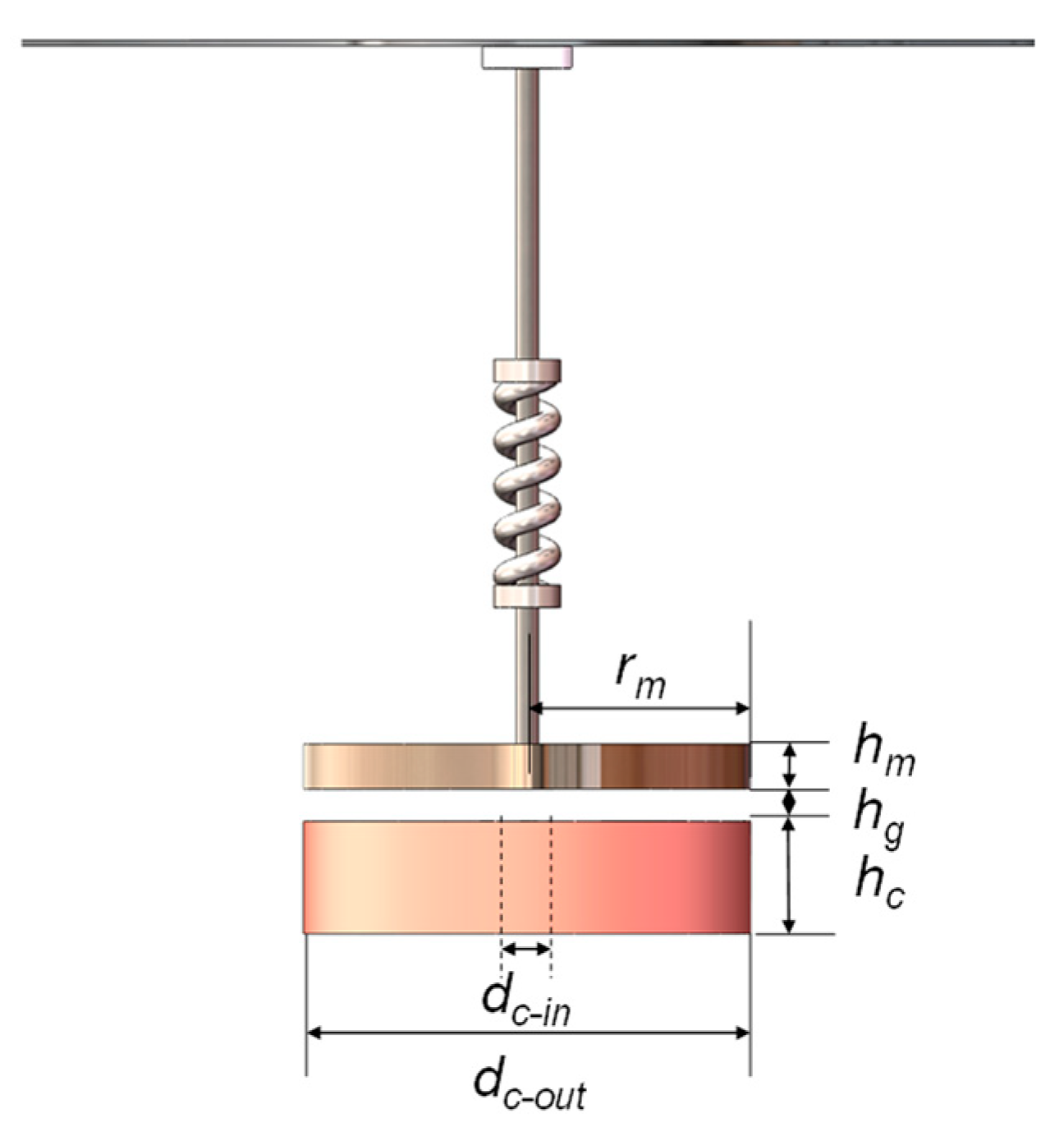
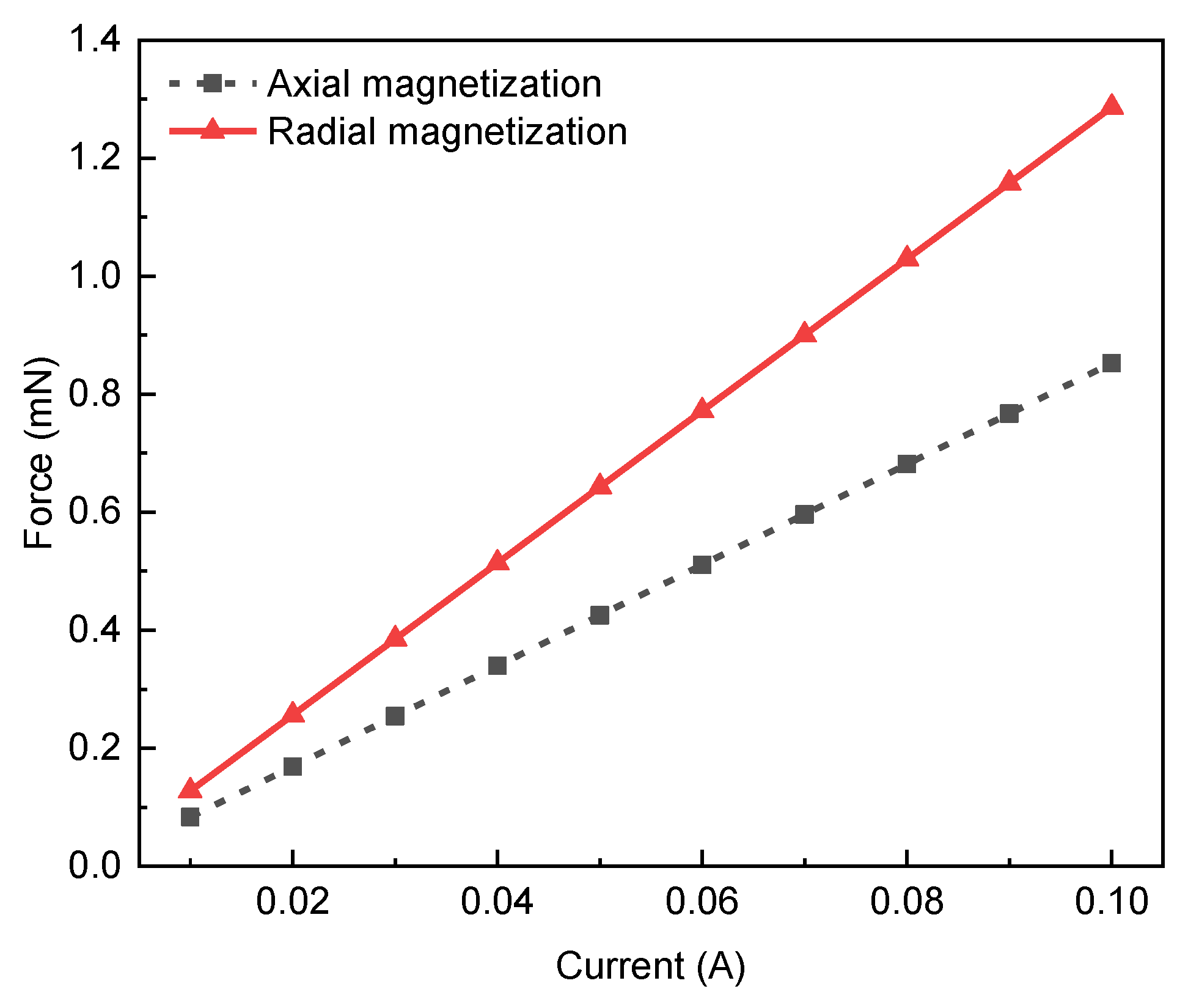
2.1. Electromagnetic Force of Micro VCA
2.2. Power Dissipation and Efficiency of Micro VCA
2.3. Response Time of VCDM
2.4. Fitting Error of VCDM
3. Design and Optimization
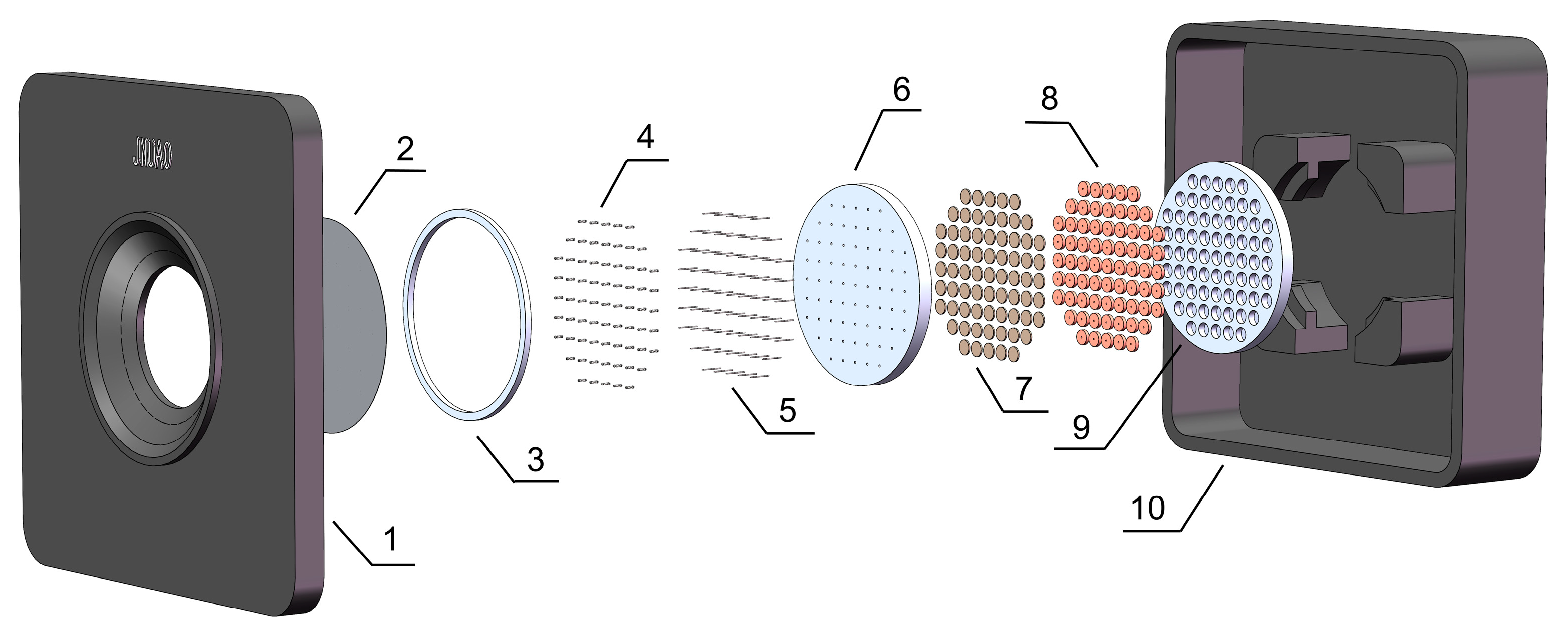
3.1. Model of Compact VCDM
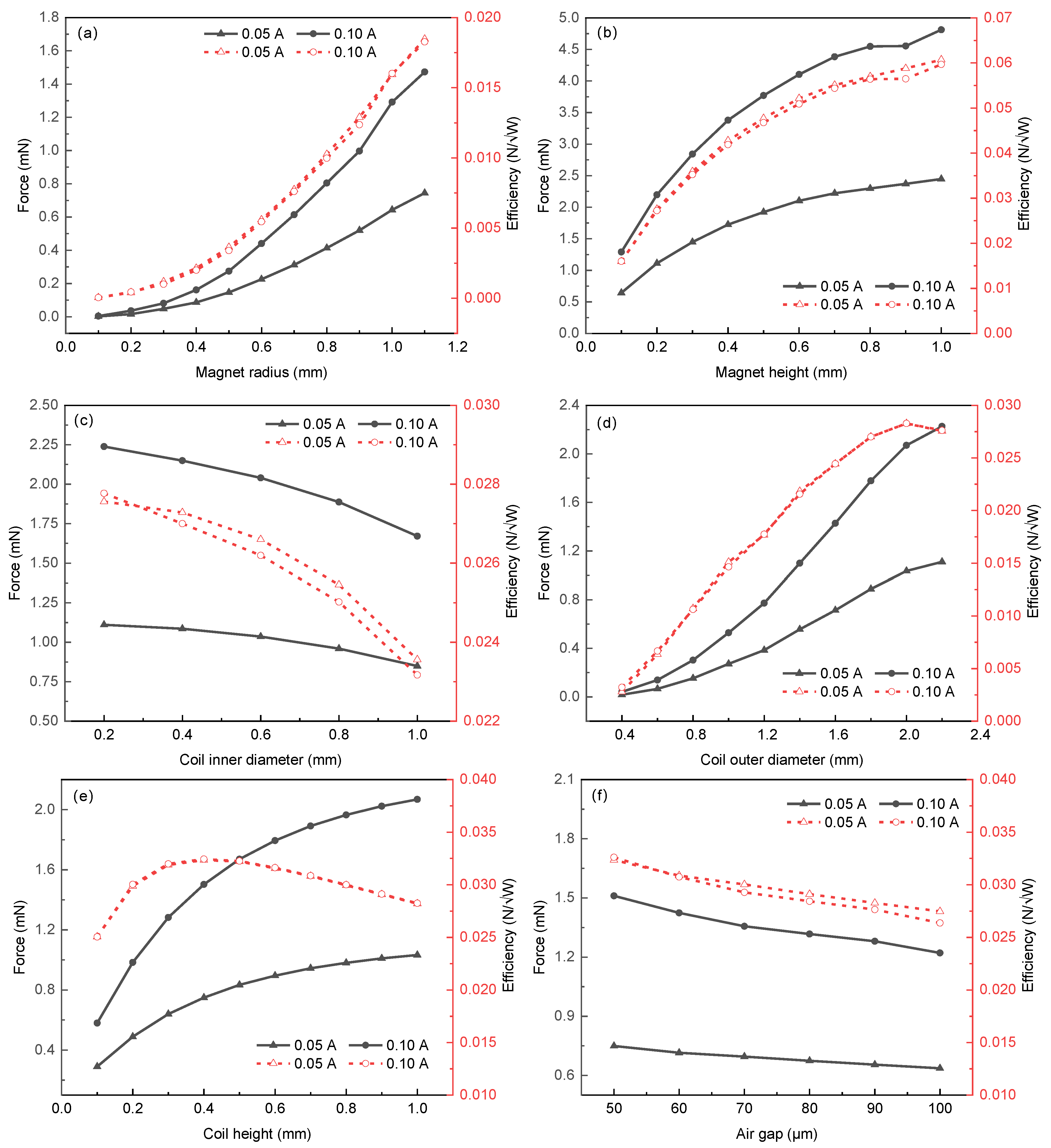
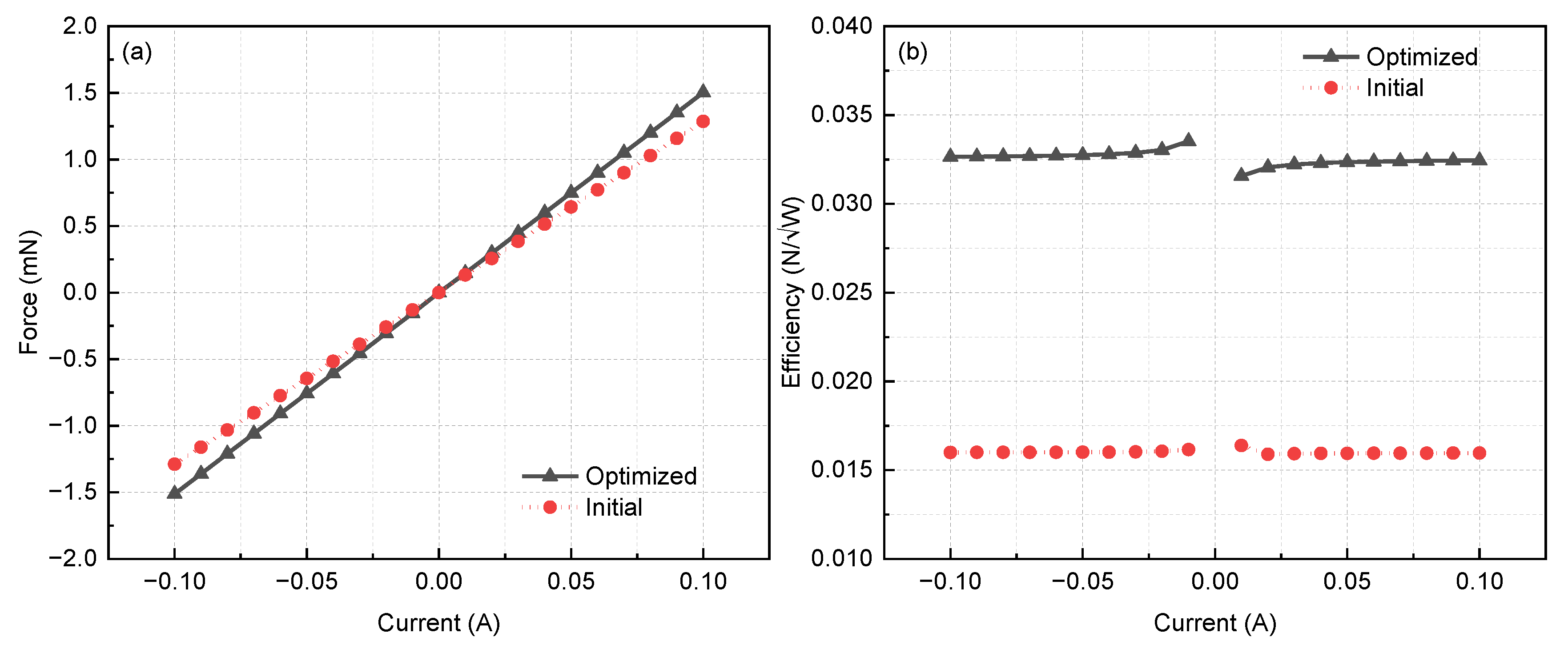
3.2. Optimization of Micro VCA
4. Discussion
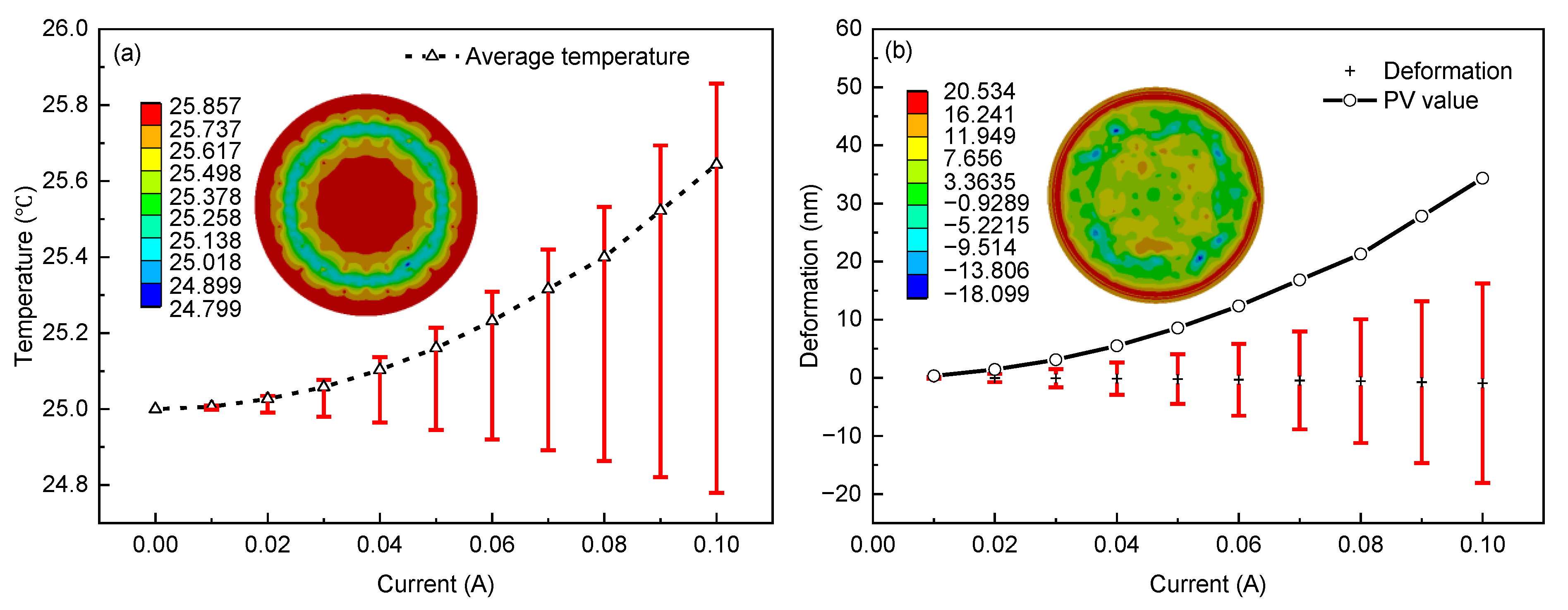
4.1. Aberration of the Thin Mirror Due to Thermal Effect
4.2. Response Time
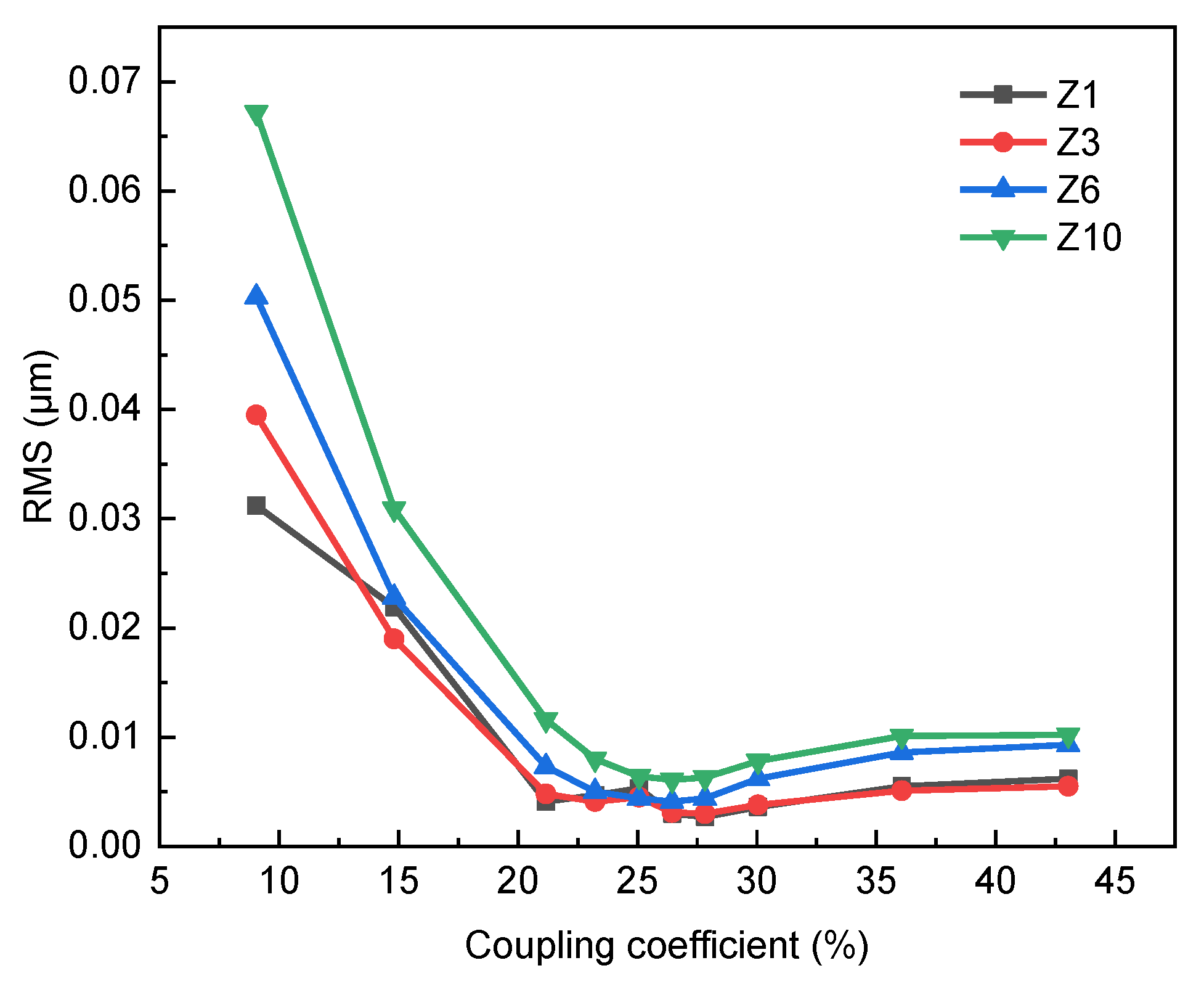
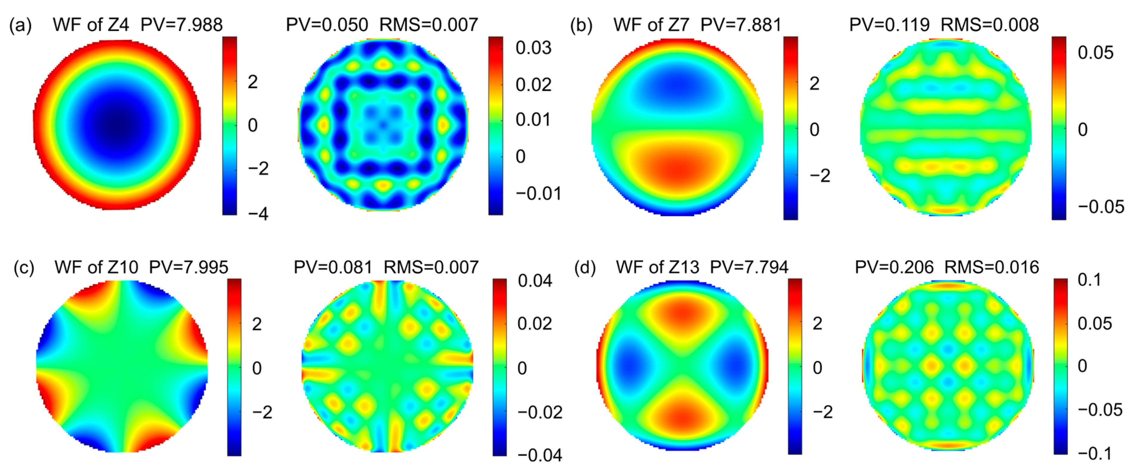
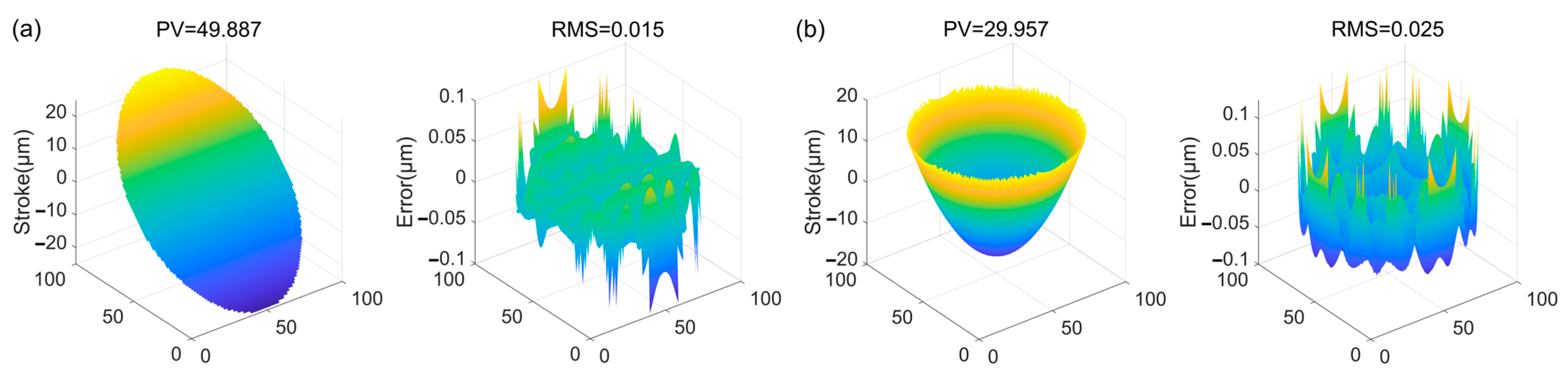
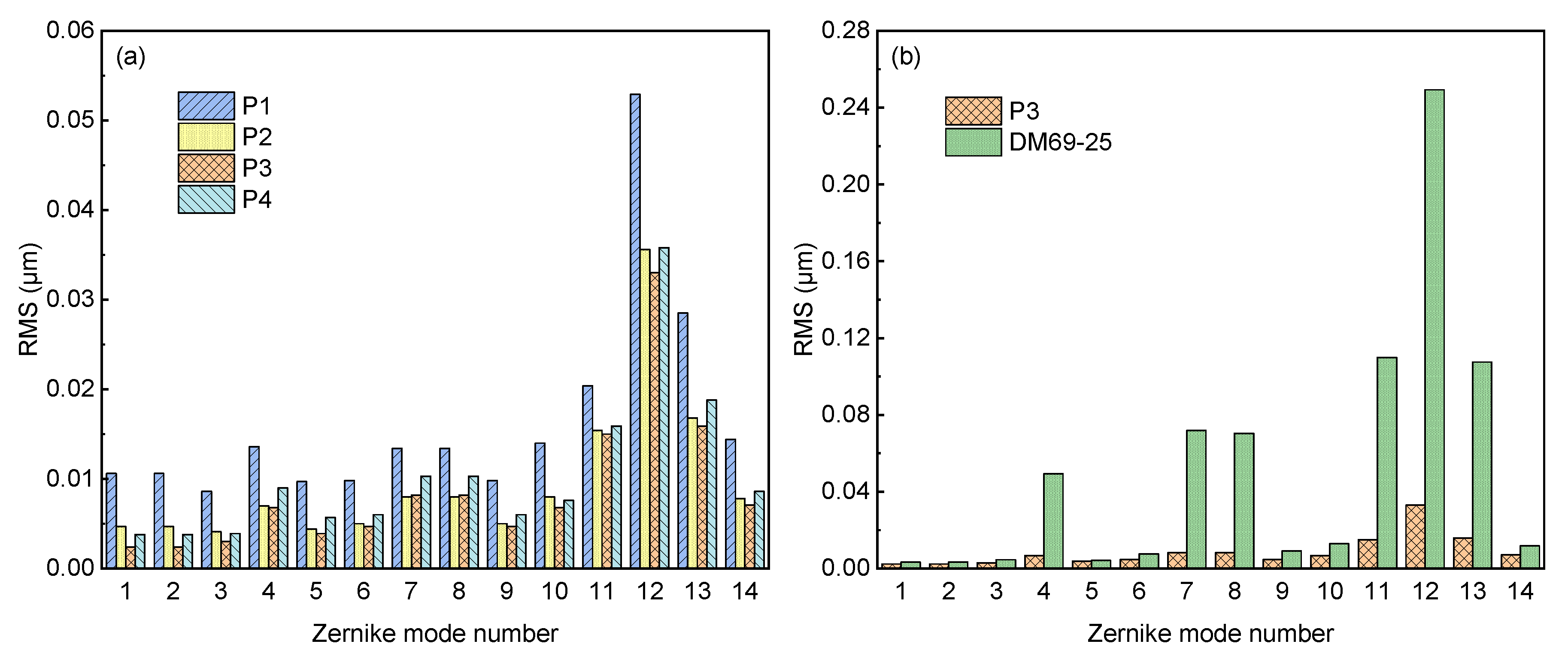
4.3. Wavefront Fitting Precision
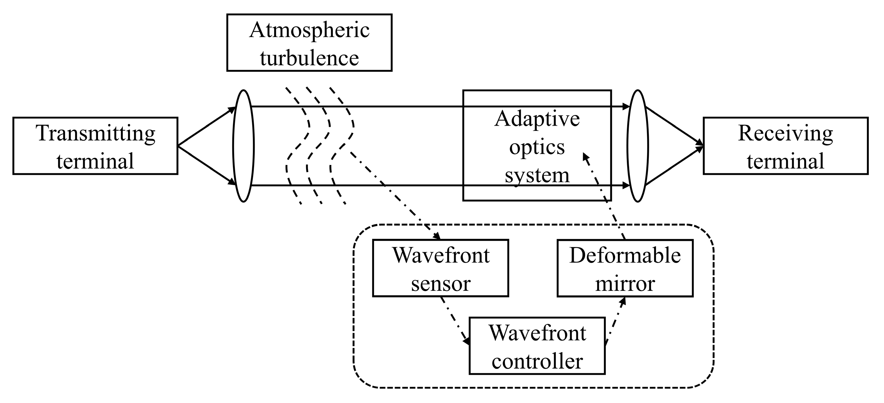
4.4. Application in Optical Communication
5. Conclusions
Author Contributions
Funding
Institutional Review Board Statement
Informed Consent Statement
Data Availability Statement
Conflicts of Interest
References
- Chi, N.; Zhou, Y.J.; Wei, Y.R.; Hu, F.C. Visible Light Communication in 6G: Advances, Challenges, and Prospects. IEEE Veh. Technol. Mag. 2020, 15, 93–102. [Google Scholar] [CrossRef]
- Rukosuev, A.; Nikitin, A.; Toporovsky, V.; Sheldakova, J.; Kudryashov, A. Real-Time Correction of a Laser Beam Wavefront Distorted by an Artificial Turbulent Heated Airflow. Photonics 2022, 9, 351. [Google Scholar] [CrossRef]
- Sabino, J.; Figueira, G.; Andre, P. Wavefront spatial-phase modulation in visible optical communications. Microw. Opt. Technol. Lett. 2017, 59, 1538–1541. [Google Scholar] [CrossRef]
- Yang, S.J.; Ke, X.Z. Experimental study on adaptive optical wavefront correction with dual mirrors in free space optical communication. Optik 2021, 242, 167146. [Google Scholar] [CrossRef]
- Hardy, J.W.; Lefebvre, J.E.; Koliopoulos, C.L. Real-time atmospheric compensation. J. Opt. Soc. Am. 1977, 67, 360–369. [Google Scholar] [CrossRef]
- Primmerman, C.A.; Murphy, D.V.; Page, D.A.; Zollars, B.G.; Barclay, H.T. Compensation of atmospheric optical distortion using a synthetic beacon. Nature 1991, 353, 141–143. [Google Scholar] [CrossRef]
- Toporovsky, V.; Kudryashov, A.; Skvortsov, A.; Rukosuev, A.; Samarkin, V.; Galaktionov, I. State-of-the-Art Technologies in Piezoelectric Deformable Mirror Design. Photonics 2022, 9, 321. [Google Scholar] [CrossRef]
- Wu, Z.Z.; Zhang, T.Y.; Mbemba, D.; Wang, Y.Y.; Wei, X.; Zhang, Z.; Iqbal, A. Wavefront sensorless aberration correction with magnetic fluid deformable mirror for laser focus control in optical tweezer system. IEEE Trans. Magn. 2021, 57, 1–6. [Google Scholar] [CrossRef]
- Kamel, A.; Kocer, S.; Mukhangaliyeva, L.; Saritas, R.; Gulsaran, A.; Elhady, A.; Basha, M.; Hajireza, P.; Yavuz, M.; Abdel-Rahman, E. Resonant adaptive MEMS mirror. Actuators 2022, 11, 224. [Google Scholar] [CrossRef]
- Bifano, T. ADAPTIVE IMAGING MEMS deformable mirrors. Nat. Photonics 2011, 5, 21–23. [Google Scholar] [CrossRef]
- Morgan, R.E.; Douglas, E.S.; Allan, G.W.; Bierden, P.; Chakrabarti, S.; Cook, T.; Egan, M.; Furesz, G.; Gubner, J.N.; Groff, T.D.; et al. MEMS deformable mirrors for space-based high-contrast imaging. Micromachines 2019, 10, 366. [Google Scholar] [CrossRef] [Green Version]
- Hamelinck, R.F.M.M. Adaptive Deformable Mirror: Based on Electromagnetic Actuators. Ph.D Thesis, Technische Universiteit Eindhoven, Eindhoven, The Netherlands, 22 June 2010. [Google Scholar]
- Liu, X.Y.; Cao, S.; Hu, D.T.; Ma, W.C.; Zhao, Z.Y.; Wu, J.J.; Zhu, H.X.; Su, Z.P.; Zhang, Y.X.; Hu, L.F. Design of voice-coil deformable mirror and its mechanical characteristics. Chin. J. Liq. Cryst. Disp. 2020, 35, 801–807. [Google Scholar] [CrossRef]
- Ahn, K.; Rhee, H.G.; Yang, H.S.; Kihm, H. CVD SiC deformable mirror with monolithic cooling channels. Opt. Express 2018, 26, 9724–9739. [Google Scholar] [CrossRef] [PubMed]
- Toporovsky, V.; Samarkin, V.; Sheldakova, J.; Rukosuev, A.; Kudryashov, A. Water-cooled stacked-actuator flexible mirror for high-power laser beam correction. Opt. Laser Technol. 2021, 144, 107427. [Google Scholar] [CrossRef]
- Wang, C.C.; Lu, S.Z.; Zhang, C.Y.; Gao, J.; Zhang, B.; Wang, S. Design and dynamic modeling of a 3-RPS compliant parallel robot driven by voice coil actuators. Micromachines 2021, 12, 1442. [Google Scholar] [CrossRef] [PubMed]
- Zhang, Z.G.; Hu, Q.L.; Ma, W.C.; Jiang, L.; Gu, H.; Wu, J.J.; Hu, L.F. Design and performance research of high efficiency variable reluctance voice coil actuator. Chin. J. Liq. Cryst. Disp. 2022, 37, 21–28. [Google Scholar] [CrossRef]
- Jarosz, J.; Mece, P.; Conan, J.M.; Petit, C.; Paques, M.; Meimon, S. High temporal resolution aberrometry in a 50-eye population and implications for adaptive optics error budget. Biomed. Opt. Express 2017, 8, 2088–2105. [Google Scholar] [CrossRef] [Green Version]
- Greenwood, D.P. Bandwidth specification for adaptive optics systems. J. Opt. Soc. Am. 1977, 67, 390–393. [Google Scholar] [CrossRef]
- Hardy, J.W.; Thompson, L. Adaptive optics for astronomical telescopes. Phys. Today 2000, 53, 69. [Google Scholar] [CrossRef] [Green Version]
- Cugat, O.; Basrour, S.; Divoux, C.; Mounaix, P.; Reyne, G. Deformable magnetic mirror for adaptive optics: Technological aspects. Sens. Actuator A-Phys. 2001, 89, 1–9. [Google Scholar] [CrossRef]
- Yu, E.; Joshi, Y.K. Natural convection air cooling of electronic components in partially open compact horizontal enclosures. IEEE Trans. Compon. Packag. Technol. 2000, 23, 14–22. [Google Scholar] [CrossRef]
- Yin, J.J.; Mao, D.B.; Fan, B.; Bian, J.; Du, J.F. High dimensional stability polyimide membrane material for space optical imaging system. Opto.-Electron. Eng. 2021, 48, 210150. [Google Scholar] [CrossRef]
- Plavec, E.; Petrinic, M.; Vidovic, M. Improving the force and time response of a DC solenoid electromagnetic actuator by changing the lower core angle. J. Electromagn. Eng. Sci. 2021, 21, 95–103. [Google Scholar] [CrossRef]
- Huang, L.H.; Rao, C.H.; Jiang, W.H. Modified Gaussian influence function of deformable mirror actuators. Opt. Express 2008, 16, 108–114. [Google Scholar] [CrossRef] [PubMed]
- Ahn, K.; Kihm, H. Moment actuator for correcting low-order aberrations of deformable mirrors. Opt. Lasers Eng. 2020, 126, 105864. [Google Scholar] [CrossRef]
- Zhang, Z.G. Structure Design and Performance Research of Modular Voice Coil Deformable Mirror; Jiangnan University: Wuxi, China, 2022. [Google Scholar]


| Serial Number | Component |
|---|---|
| 1 | Front shell |
| 2 | Thin mirror |
| 3 | O-ring |
| 4 | Springs |
| 5 | Struts |
| 6 | Spring fixing plate |
| 7 | Permanent magnets |
| 8 | Voice coils |
| 9 | Substrate |
| 10 | Back shell |
| Parameters | Unit | Values | Step |
|---|---|---|---|
| Magnet radius | [mm] | 0.1 ≤ rm ≤ 1.1 | 0.1 |
| Magnet height | [mm] | 0.05 ≤ hm ≤ 1 | 0.05 |
| Coil inner diameter | [mm] | 0.2 ≤ dc-in ≤ 1 | 0.2 |
| Coil outer diameter | [mm] | 0.4 ≤ dc-out ≤ 2.2 | 0.2 |
| Coil height | [mm] | 0.1 ≤ hc ≤ 1 | 0.1 |
| Air gap | [μm] | 50 ≤ hg ≤ 100 | 10 |
| Thermal Conductivity | Coefficient of Thermal Expansion | Density | Young’s Modulus | Poisson’s Ratio | |
|---|---|---|---|---|---|
| Material | [W/m/°C] | [/°C] | [kg/m3] | [Pa] | [/] |
| CP1 Polyimide | 0.25 | 5.1 × 10⁻⁵ | 1540 | 2.1 × 10⁹ | 0.34 |
| 316 Stainless Steel | 13.44 | 1.478 × 10⁻⁵ | 7954 | 1.95 × 10¹¹ | 0.25 |
| FR-4 Epoxy | 0.294 | 1.688 × 10⁻⁵ | 1900 | 2.64 × 10¹⁰ | 0.1543 |
| NdFe35 | 7.7 | 3.2 × 10⁻⁶ | 7450 | 1.6 × 10⁸ | 0.24 |
| Copper | 112.1 | 1.999 × 10⁻⁵ | 8267 | 9.995 × 10¹⁰ | 0.345 |
| Aluminum Alloy | 114 | 2.3 × 10⁻⁵ | 2770 | 7.1 × 10¹⁰ | 0.33 |
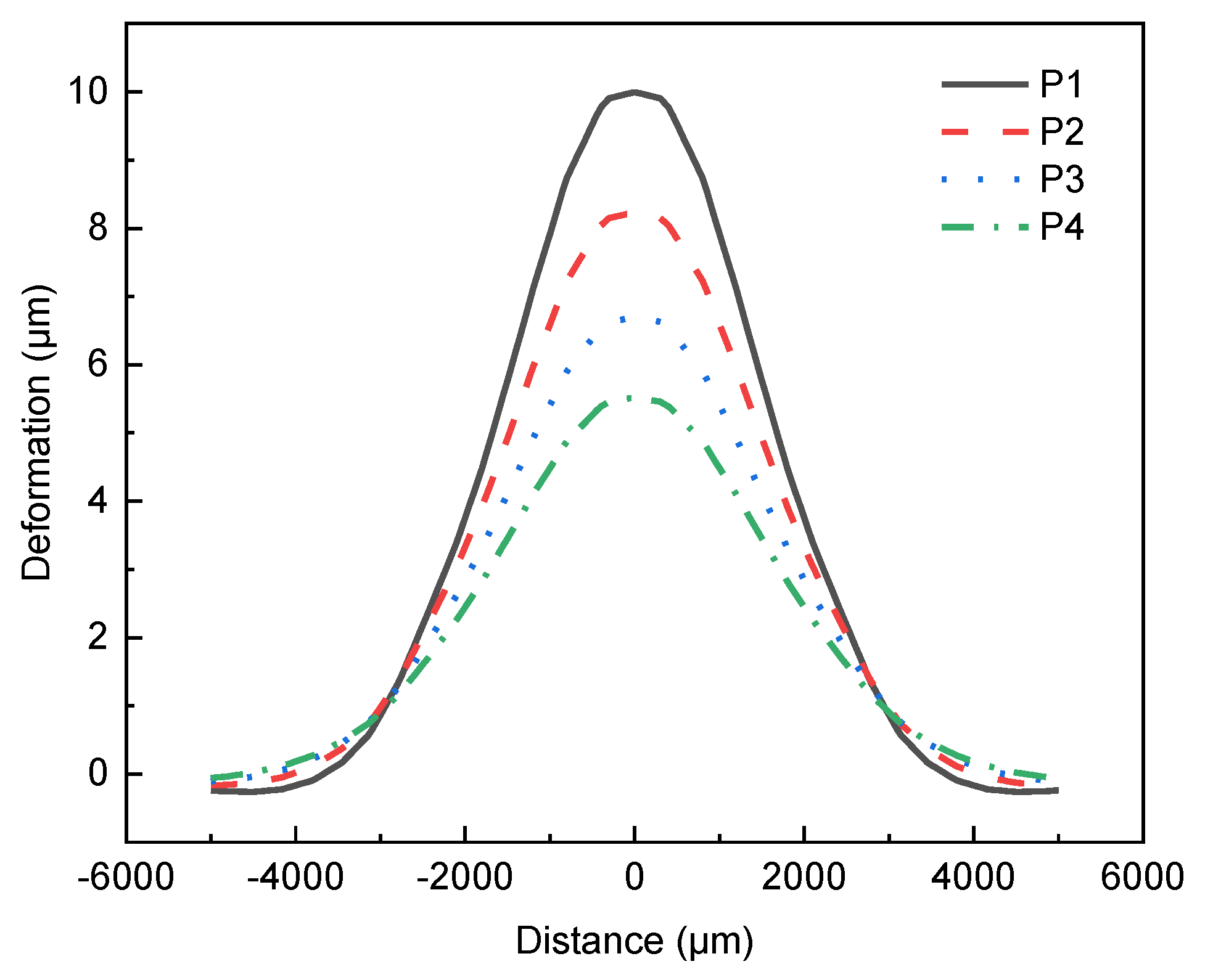
| Pattern | Thickness | Stiffness | First Resonance | k | ω | α |
|---|---|---|---|---|---|---|
| P1 | 35 μm | 55 N/m | 2019.9 Hz | 9.958 | 19.78% | 2.191 |
| P2 | 40 μm | 61 N/m | 2010.8 Hz | 8.214 | 23.22% | 2.111 |
| P3 | 45 μm | 70 N/m | 2045.2 Hz | 6.694 | 25.81% | 2.049 |
| P4 | 50 μm | 80 N/m | 2085.8 Hz | 5.525 | 28.03% | 1.995 |
Disclaimer/Publisher’s Note: The statements, opinions and data contained in all publications are solely those of the individual author(s) and contributor(s) and not of MDPI and/or the editor(s). MDPI and/or the editor(s) disclaim responsibility for any injury to people or property resulting from any ideas, methods, instructions or products referred to in the content. |
© 2023 by the authors. Licensee MDPI, Basel, Switzerland. This article is an open access article distributed under the terms and conditions of the Creative Commons Attribution (CC BY) license (https://creativecommons.org/licenses/by/4.0/).
Share and Cite
Jiang, L.; Hu, L.; Hu, Q.; Xu, X.; Wu, J.; Yu, L.; Huang, Y. Sixty-Nine-Element Voice Coil Deformable Mirror for Visible Light Communication. Photonics 2023, 10, 322. https://doi.org/10.3390/photonics10030322
Jiang L, Hu L, Hu Q, Xu X, Wu J, Yu L, Huang Y. Sixty-Nine-Element Voice Coil Deformable Mirror for Visible Light Communication. Photonics. 2023; 10(3):322. https://doi.org/10.3390/photonics10030322
Chicago/Turabian StyleJiang, Lv, Lifa Hu, Qili Hu, Xingyu Xu, Jingjing Wu, Lin Yu, and Yang Huang. 2023. "Sixty-Nine-Element Voice Coil Deformable Mirror for Visible Light Communication" Photonics 10, no. 3: 322. https://doi.org/10.3390/photonics10030322