1. Introduction
Since Arthur Ashkin’s groundbreaking work in the early 1970s [
1], optical trapping has gained significant interest [
2,
3,
4]. Unlike traditional optical tweezers that rely on a tightly focused focal spot in the far field, plasma optical tweezers utilizing the evanescent field produced by exciting micro- and nano-scale structures offer the advantages of surpassing the diffraction limit and reducing the need for high incident power [
5,
6,
7,
8]. Among the plasma optical tweezers, nano-optical conveyors stand out as they possess the unique ability to not only capture nanoparticles, but also transport them in a planar manner [
9,
10,
11,
12,
13,
14,
15,
16,
17,
18,
19,
20,
21,
22,
23,
24,
25,
26].
Recently, a type of nano-optical conveyor belt has emerged that combines the features of planar waveguides and plasma structures [
9,
10,
11,
12,
13]. For instance, a bidirectional transport of nanoparticles and cells was achieved using an optical conveyor belt assembled from natural biological cells [
13]. Another type of nano-optical conveyor belt is purely based on plasma structures, such as the C-shaped nano aperture array [
14,
15,
16], nano-ring array [
17,
18,
19], nano-disks array [
20,
21,
22], nano-bowtie antenna array [
23], nanoholes array [
24], and plasmonic metasurface [
25,
26], among others. However, most of the existing optical transport technologies have complex, specially designed structures and are limited to unidirectional, single-channel transport. Optical transport is typically achieved by changing the polarization and wavelength of the incident beams, but this requires bulky optical devices, making the nano-optical conveyor belt larger, and mechanical regulation can affect work efficiency and stability. This study presents a multichannel plasma nano-optical conveyor belt based on a phase-driven rectangular grating, which has been verified by calculated and numerical simulation results to exhibit exceptional performance.
2. Structure Design and Optimization
Typically, square slit distributions are utilized to produce arrays of SPP focal spots [
7,
27,
28]. However, these arrangements are not suitable for transporting particles over extended distances in a specific direction. To address this, we employed rectangular grating distributions to create long and narrow transmission channels. The asymmetrical aspect of the rectangle, with varying lengths and widths, presents a more challenging yet diverse SPP field characteristic to control.
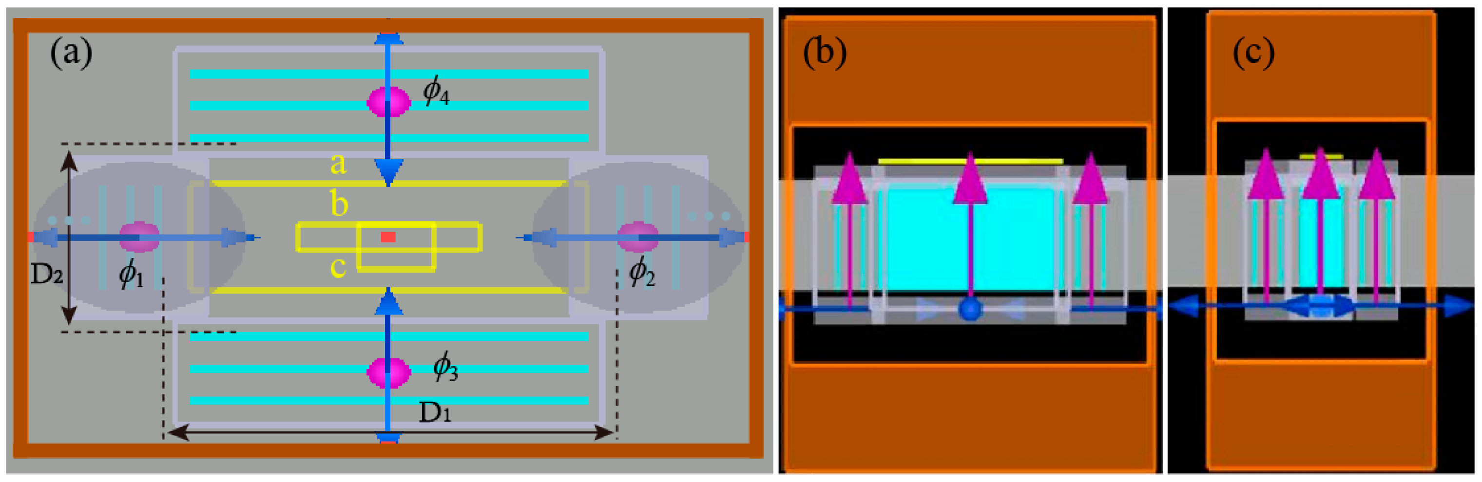
Figure 1 depicts the basic model as established by Lumerical FDTD software. Each grating comprises three slits with a period of 615 nm and a width of 194 nm, embedded in a 120 nm-thick silver film. The thickness was optimized to prevent interference from incident light. The spacing between two horizontal and two vertical gratings (D
1 = 10 μm, D
2 = 3.6 μm) differs. The gratings are illuminated from the back side by four Gaussian beams with a wavelength of 632.8 nm and linear polarization, generated by a vector light field generator with the assistance of two LC-SLMs [
29,
30]. All polarization directions are perpendicular to the respective gratings, ensuring effective excitation of the SPPs [
29,
30]. Perfect boundary conditions were applied in all directions with power monitors placed 20 nm above the silver surface.
The left and right gratings are excited by horizontally polarized light, generating a horizontal SPP standing wave. Meanwhile, the upper and lower gratings are excited by vertically polarized light, resulting in a vertical standing wave. Interference between these two SPP standing waves creates SPP focal spots. When only the left and right gratings are excited, a horizontal SPP standing wave is established at the center of the structure: [
7,
31]
where
and
are the initial phases of two SPP waves. The phase difference between the SPPs is solely dependent on the phase of the illuminating excitation beams, as they impinge on the gratings at a perpendicular angle, i.e., [
7,
31]
where
and
are phases of horizontal excitation beams. The presence of opposite charge distributions on either side of the grating results in an additional phase difference
.
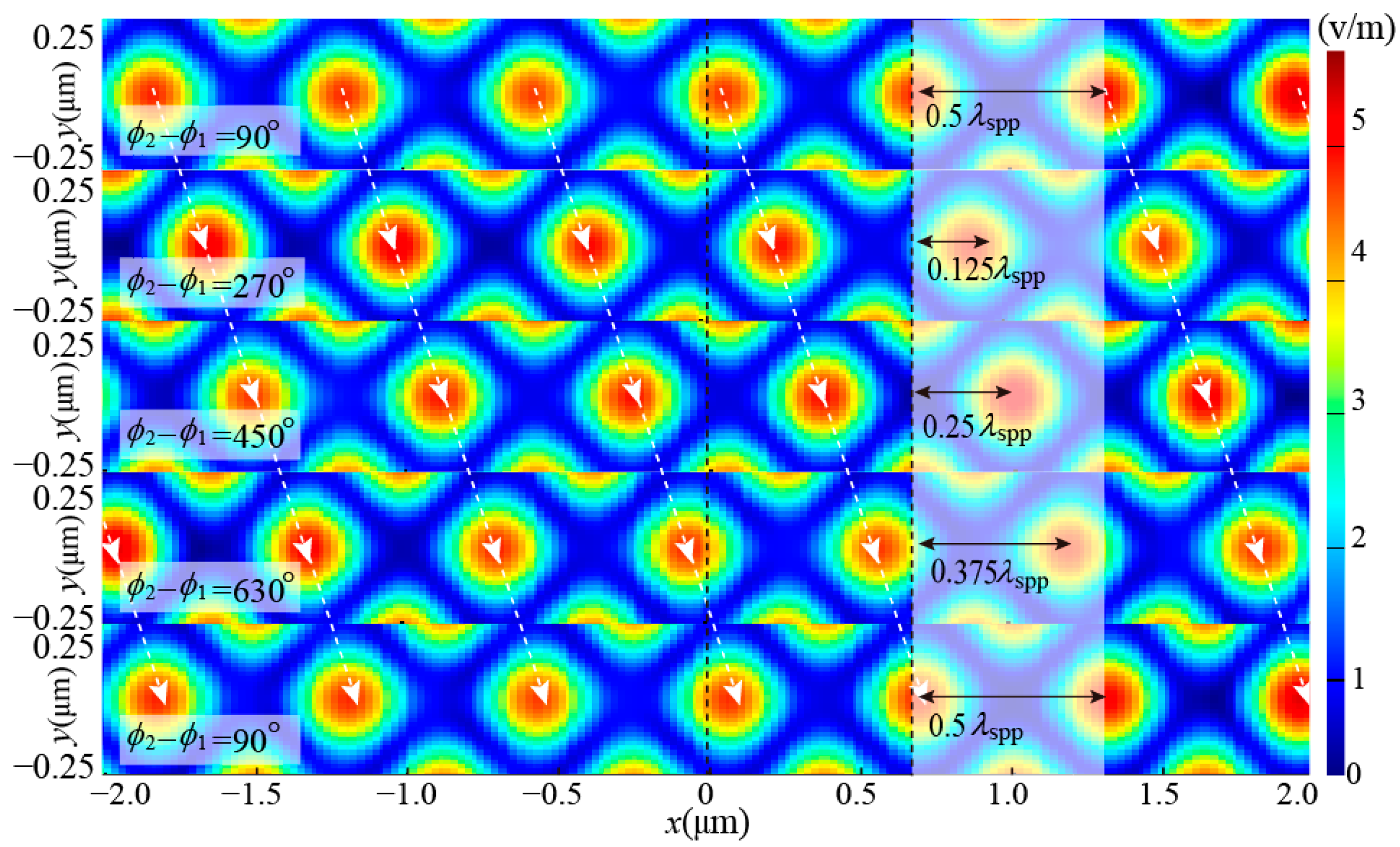
The horizontal SPP standing wave can be moved by altering the phase difference between the horizontal excitation beams, as stated in Equations (1) and (2). This method can also move the SPP focal spots produced by the interference of the two standing waves.
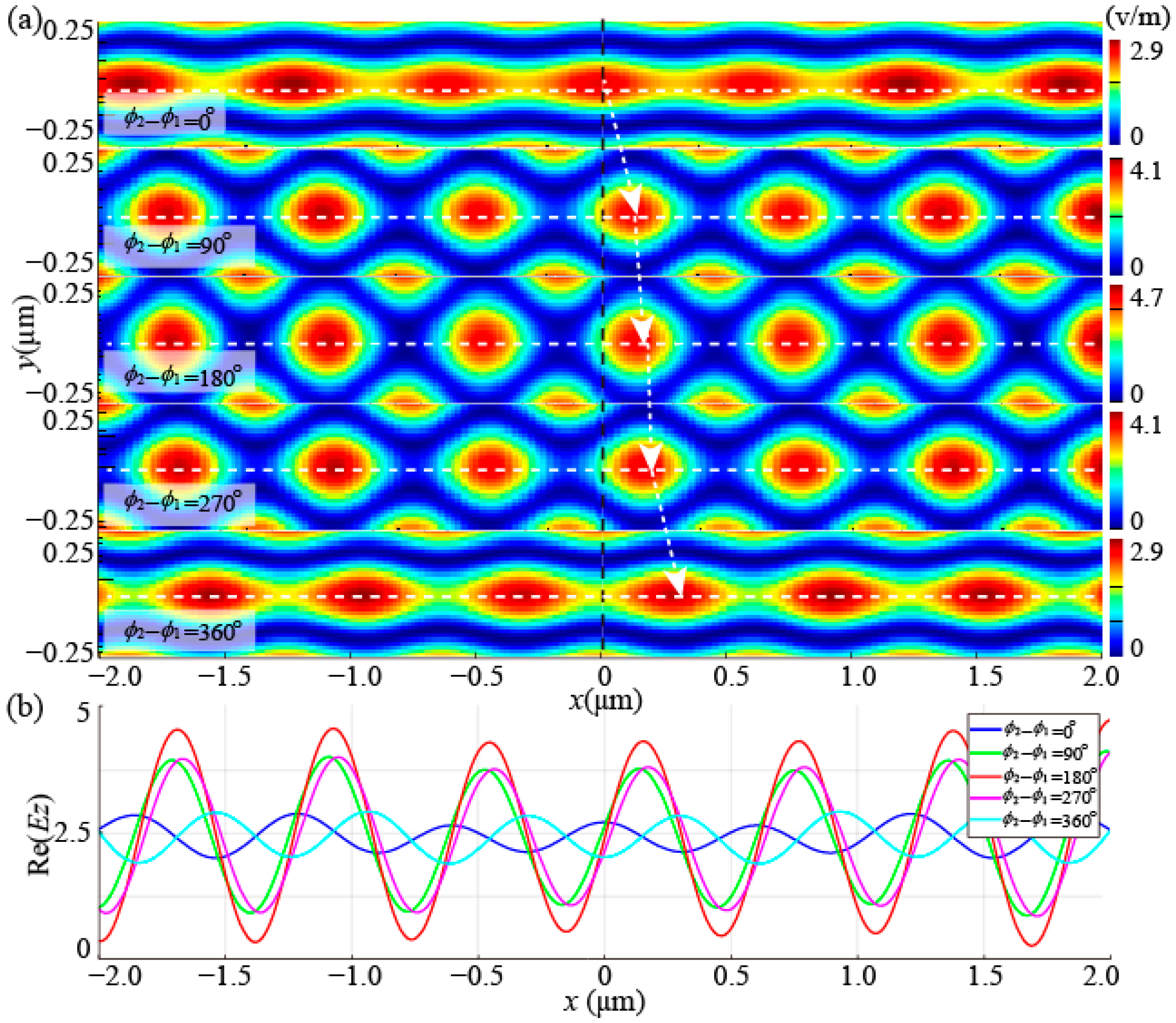
Figure 2a demonstrates that the SPP focal spots move towards the right as the phase difference between the horizontal excitation beams increases, as detected by monitor “b”. However, it is noticed that some of the focal spots are distorted, and the moving steps indicated by the white arrow are not uniform. This is more prominent in the linear intensity distribution along the
x-axis in
Figure 2b, which implies a hindrance to the precise capture and stable transport of nanoparticles. Thus, optimization of the structure is required.
Analyzing the electric field distribution of the optimal (
) and the worst-case (
) focal spots in
Figure 2a, reveals while vertical SPP standing waves exhibit consistent intensity (with a maximum of intensity 2.5), horizontal SPP standing waves exhibit varying intensities (with a maximum intensity of 1.3 and 0.4). The disparity between the intensity of the horizontal and vertical standing waves can be attributed to the asymmetry between the length and width of the rectangular structure. To address this issue, the number of slits in the horizontal gratings was increased to improve the intensity of the horizontal SPP standing wave. The results indicate that by increasing the number of slits in the left and right gratings to five, the intensity of the horizontal standing wave can reach up to 2.7, which is more closely aligned with the intensity of the vertical standing wave. If the number of horizontal slits is less than five, the horizontal SPP standing wave is weaker, leading to the deformation of the focal spots. On the contrary, if the number exceeds five, the horizontal SPP standing wave becomes stronger than the vertical SPP standing wave, causing another form of focal spot deformation. Therefore, to achieve optimal results, the structure was optimized with five slits for the horizontal gratings.
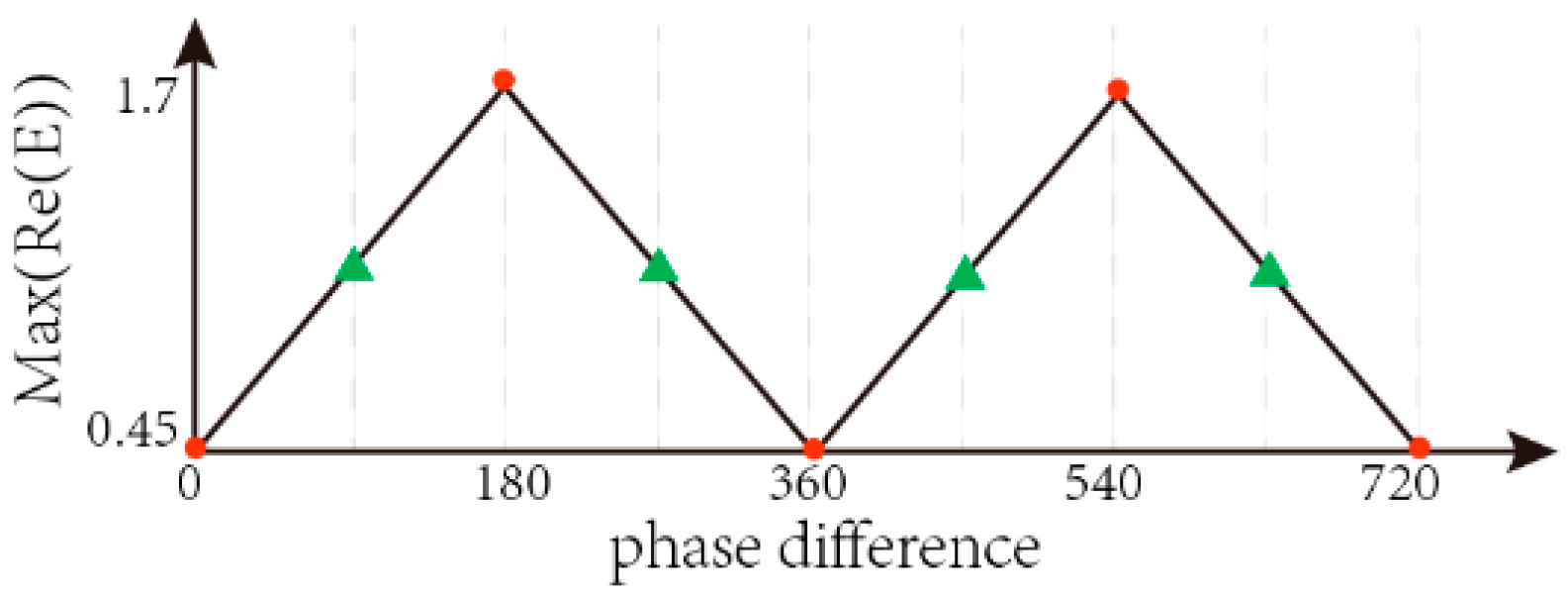
Furthermore, it is crucial to keep the uniformity of the SPP focal spot intensity during the process to ensure stable particle transport. To tackle this concern, simulations were carried out exclusively on the horizontal gratings. The electric field at the center of the structure is depicted in
Figure 3. As it can be observed, when the phase difference between two horizontal excitation beams is 0°, 360°, and 720°, the electric field reaches its lowest point. Although the electric field attains its maximum at 180° and 540°, it exhibits only two steps in a cycle. In this two-step cycle, as the focal spots move ahead by 1/2 cycle, the captured particles will fall behind and be positioned in the center of the new focal spots, thus resulting in a zero force, and hindering any further movement. Conversely, the electric field remains constant when the phase difference is 90°, 270°, 450°, and 630°. In this four-step cycle, as the focal spots move ahead by 1/4 cycle, the captured particles remain inside the new focal spots, hence attracting them towards the center of these new focal spots. Additionally, there are other four phase groups that exhibit the same maximum real part of the electric field; however, taking into consideration both the electric field intensity and equidistant steps, 90°, 270°, 450°, and 630° are the optimal choices.
To ensure stable capture and transport of particles, the model must be optimized through the adjustment of the number of slits in the horizontal gratings and the regulation of the phase difference of the horizontal excitation beams.
3. Results and Discussion
In this section, the functionality of the proposed design is evaluated through the calculation of optical force and trapping potential energy. To accurately assess the effect of the design, a gold bead of 20 nm in diameter (ε
Au = −5.62651 + 2.20633i) is selected as the target, as metal particles receive more radiation force, and the gradient force will decrease sharply with a decrease in the radius. The surrounding medium is water with a refractive index of 1.338. Although the metal particles are known to have strong scattering and absorption properties, it has been established that these forces are negligible in the SPP field. As a result, this study focuses on analyzing the gradient force alone [
3,
6]. According to the principle of dipole approximation, for a Rayleigh metallic particle with radius ‘a’ (a ≪ λ), the gradient force exerted on it is determined using the following equation [
3,
5]
where
is the dielectric constant of the free space and
is the polarizability of the metallic particle:
where
and
are the dielectric constants of the metal and the ambient, respectively.
The trapping potential energy, which is the energy required to move a particle from within the trap to an infinite distance, for a particle located at r
0 can be calculated as [
5,
6]
where
is the optical force. The trapping potential energy of a particle captured solely by gradient force is represented as
The maximum trapping potential energy, which is the depth of the potential well, serves as a crucial metric in evaluating the efficiency of optical trapping. To ensure the stability of particle capture and prevent escape due to Brownian motion, the depth of the potential well should be at least 10 k
BT, where k
B is Boltzmann’s constant and T represents the absolute temperature in the trap [
5]. A deeper potential well results in a more stable capture. Here, it is worth noting that Equations (3)—(5) are only valid for conservative forces. For non-conservative forces, Helmholtz–Hodge decomposition should be used to calculate the potential [
32].
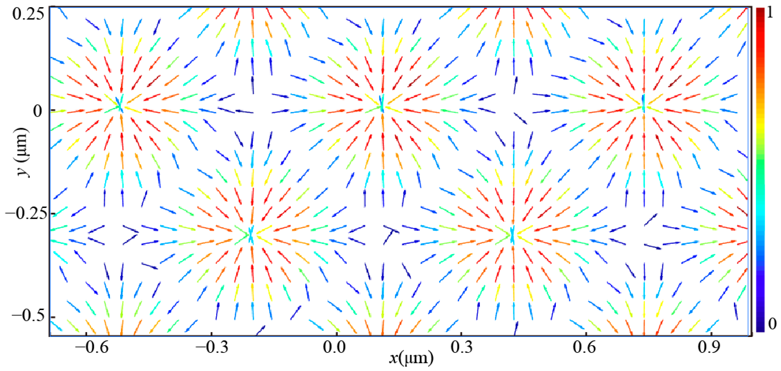
3.1. Distribution of Electric Field and Optical Force in Nano-Optical Conveyor Belt
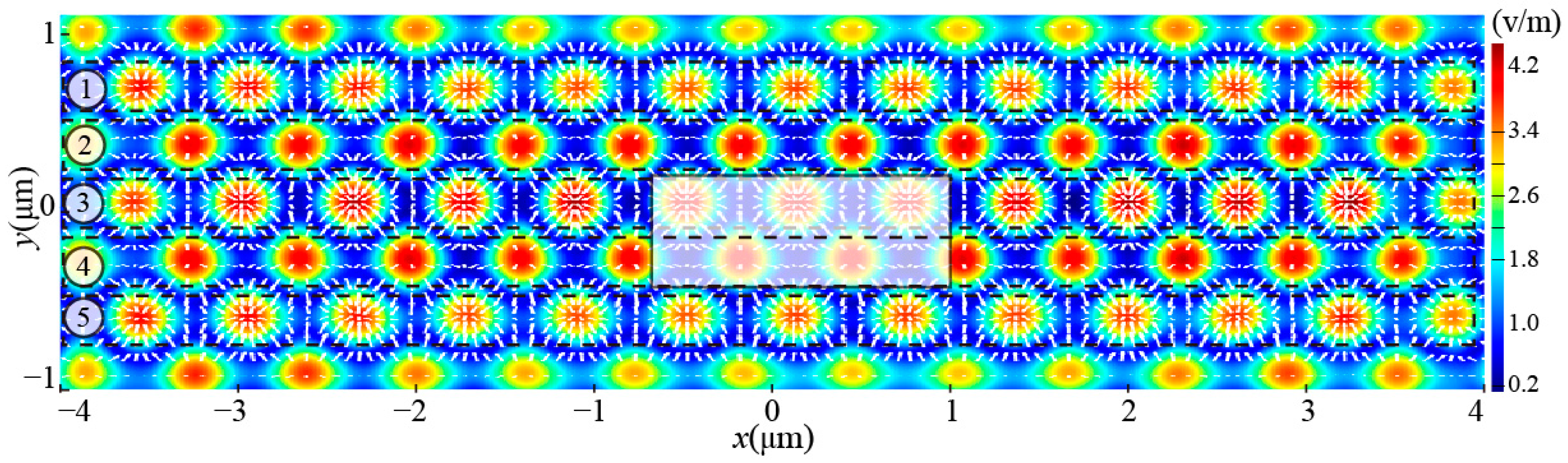
The electric field distribution measured by monitor “a” is depicted in
Figure 4. The SPP focal spots are generated and arranged in a uniform manner. Electric field vectors at the focal spots extend from the outside to the inside in rows ①, ③, and ⑤, while in rows ② and ④, they extend from the inside to the outside. The optical gradient force, which depends on the intensity gradient and points in the direction of maximum intensity, enables each focal spot to serve as a trap, capturing particles to its center. Furthermore, as focal spots are moved horizontally, each row of focal spots can function as a transport channel thus forming multiple horizontal transport channels. It is important to note that the SPP focal spots near the upper and lower gratings are weak and severely distorted, thus unable to support particle capture and transport. This structure features five effective transport channels, with the number of channels determined by the length of the left and right grating slits, and the transport distance dependent on the length of the upper and lower grating slits. Consequently, the number of channels and transport distance can be tailored to meet specific needs. It is worth mentioning that while increasing the number of channels will improve transport efficiency, it will also lower capture efficiency due to the attenuation of SPP.
All effective SPP focal spots displayed in
Figure 4 are nearly uniform. For a clearer illustration of the force distribution, several focal spots within the translucent white area in
Figure 4 have been enlarged in
Figure 5. The normalized horizontal optical force distribution of the selected spots, measured by monitor “c”, reveals that all force vectors are directed towards the center of the SPP focal spots. The optical force gradually increases from the edge to the center, until reaching the maximum at the symmetrical positions where the opposing forces are equal and result in a net force of zero. This indicates that the particles will be attracted toward the center of focal spots and ultimately stabilized there. Furthermore, it can be seen from
Figure 4 and
Figure 5 that misaligned SPP focal spots in adjacent channels can lead to a larger trap spacing between the channels, reducing the risk of crosstalk.
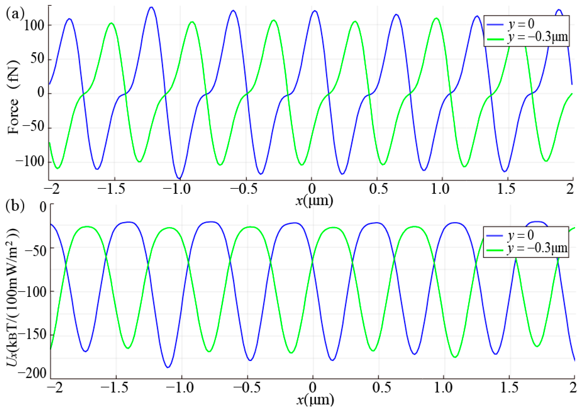
3.2. Optical Force and Potential Well in the Plasma Nano-Optical Conveyor belt
The graphical representation of the optical force and trapping potential energy exerted on the target particle along y = 0 (blue line) and y = −0.3 μm (green line) can be found in
Figure 6. These two lines correspond to the center lines of channels ③, and ④, respectively. As shown in
Figure 6a, the horizontal gradient force in both channels exhibits a uniform periodic change, with multiple force balance points forming at the center of each channel’s focal spots. This results in a pulling force towards each balance point from both sides, demonstrating the presence of multiple effective traps in each channel which significantly improves the capture efficiency. In addition, the comparison of y = 0 and y = −0.3 μm reveals a greatly similar force distribution, with only a half-period lag, implying that multiple channels can be utilized for particle transport.
In
Figure 6b, the trapping potential energy exerted on the target particle is shown, with a normalization to an excitation power density of 100 mW/m
2. The figure displays multiple potential wells present in each channel. These wells have a minimum depth of around 160 K
BT, ensuring that they can effectively counteract Brownian motion and securely capture particles. Moreover, the large area of silver film in this structure contributes to rapid heat dissipation, thereby minimizing the impact of photo-thermal effects.
3.3. Particle Transport in the Plasma Nano-Optical Conveyor Belt
To demonstrate the transport capability of the conveyor, the movement of focal spots was tested by adjusting the phase difference of the horizontal excitation beams. Taking the middle channel as an example, the electric field distribution detected by monitor “b” is shown in
Figure 7. As compared to
Figure 2a, it can be seen that as the phase differences of horizontal beams change from 90° to 270°, 450°, 630°, and 810 (90°), all focal spots have uniformly shifted from the left to the right, maintaining the same intensity. This demonstrates that particles can be stably captured and transported. Furthermore, the transport distance of SPP on the silver surface can reach hundreds of microns; thus, the effective transport distance for this design can conservatively be estimated to reach tens of microns. Finally, with the phase difference of opposite signs, particles can be transported in the opposite direction. Therefore, this structure can realize bidirectional transport by changing the phase difference between horizontal excitation beams.
The distribution of the linear electric field intensity along the
x-axis, corresponding to the results shown in
Figure 7, is depicted in
Figure 8. It can be observed that the peak intensity of the electric field remains constant while shifting evenly to the right. Both
Figure 7 and
Figure 8 demonstrate that the novel plasma nano-optical conveyor possesses phase-addressing capabilities. With each change in the phase difference, the optical force moves the captured particles to a new address, i.e., the center of the new SPP focal spots. By continuously changing the phase difference through LabVIEW control, the captured particles can be transported over a long distance. The use of a liquid crystal spatial light modulator (SLM) to achieve phase changes [
29,
30], as opposed to switching the wavelength and polarization of the excitation beams, enhances both efficiency and stability.
The results have demonstrated the successful generation of multiple parallel channels and the stable capture and transportation of particles using the proposed plasma nano-optical conveyor belt.
4. Conclusions
In this study, a plasma nano-optical conveyor based on a grating array with a rectangular distribution is designed, which exhibits exceptional performance in the stable capture and dynamic transport of gold particles. This design boasts several advantages over existing nano-optical conveyor belts, including a straightforward structure, greater ease of control over transport channels and distances, as well as improved stability and efficiency of phase-driven addressing compared to the wavelength and polarization-driven addressing. Multiple transport channels, each with multiple potential wells, enhance trapping and transport efficiency, while the misaligned distribution suppresses crosstalk between adjacent channels. Moreover, bidirectional transport can be achieved by adjusting the positive and negative phase difference between the horizontal excitation beams. The large silver film area in the structure also provides good heat dissipation and promotes stable capture. However, the effective transport distance in this design is limited due to the attenuation of SPPs during transmission. Despite this, the study provides a novel solution for optical manipulation, with potential applications in particle sorting, stacking, and transport. Further experimental research is needed to fully realize its potential and promote its use.


