1. Introduction
The angular momentum (AM) of light is an important property of nonparaxial light fields with different polarization states [
1,
2]. The angular momentum of light can be decomposed into the spin angular momentum (SAM) and the orbital angular momentum (OAM) [
3,
4]. Of special interest is the study of the AM in the tight focus of light [
5,
6]. A recent review is dedicated to the angular momentum of light [
7]. A number of works [
8,
9,
10] are dedicated to spin-orbital conversion, which is inherent in the angular momentum and is especially prominent in the tight focus. In the tight focus, interesting optical phenomena related to the AM and spin-orbital conversion are known: the Hall effect [
11,
12,
13,
14,
15], “photonic wheels” [
16], and reverse energy flow [
17,
18]. The behavior of light in the tight focus is adequately described by the Richards-Wolf (RW) theory [
19]. In [
20,
21], the Poynting vector (electromagnetic energy flow) is shown to be the sum of two vectors: orbital flow and spin flow. The spin flow does not carry light energy, although it generates the SAM vector that can be transferred to an absorbing small particle and cause its rotation about its center of mass. The presence of the spin term in the Poynting vector explains the reason for the reverse flow in the focus [
17]. If the spin flow has a negative longitudinal component (parallel to the optical axis) and is of greater magnitude than the orbital energy flow (canonical energy flow), then the Poynting vector has a negative longitudinal component in this area of space.
In this work, based on the RW formalism, we derive exact expressions for the longitudinal components of the AM, SAM and OAM vectors in the focal plane of an optical vortex with right circular polarization. It turns out that the sum of the SAM and OAM is not equal to the AM. We find in the literature [
22] a general expression for the AM vector via the SAM and OAM vectors. It turns out that only the total AM (integrated over the whole space) is equal to the sum of total momenta SAM and OAM.
2. Components of the Electric and Magnetic Field Vectors in the Focus
Here we consider an initial light field with the transverse components of the electric field strength vector described by the following Jones vector:
where
φ is the azimuthal angle in the plane of the exit pupil of the aplanatic optical system,
θ is the polar angle, describing the tilt of the light rays to the optical axis,
A(
θ) is the amplitude of the initial light field (real-valued function), rotationally symmetrical with respect to the optical axis,
n is the topological charge of the optical vortex (integer number), and (1,
i) is the transposed Jones vector for right circular polarization. For the initial field (1), tightly focused by an aplanatic system (ideal spherical lens), the RW formalism [
19] allows the derivation of all the components of the electric and magnetic field strength vectors near the tight focus [
23]:
In Equation (2),
Iν,μ denote the following integrals, where the first index is the type of integral (
ν = 0, 1, 2) and the second index (
μ = 0, ±1, ±2, …) is equal to the order of the Bessel function
Jν(
ξ) in the integrand:
where
k = 2π/
λ is the wavenumber of light with the wavelength
λ, f is the focal distance of an aplanatic system, (
r,
φ,
z) are the cylindrical coordinates,
θ0 is the maximal tilt angle of rays to the optical axis, defining the numerical aperture of the aplanatic lens NA = sin(
θ0),
ξ =
krsin(
θ). Expressions (2) allow the derivation of the expressions for all main characteristics of light in the focus (at
z = 0).
3. Intensity of Light, the Poynting Vector, and the Spin Angular Momentum Vector in the Focus
From Equation (2), we obtain an expression for the intensity distribution in the focus of the field (1):
As seen in Equation (4), the intensity in the focus is independent of the azimuthal angle φ, i.e., circularly symmetric. On the optical axis (r = 0), the intensity is nonzero only at n = 0, −1, −2. For other values n, the intensity (4) on the optical axis is zero, i.e., there is a light ring in the focus.
Further, using Equation (2), we derive expressions for the components of the Poynting vector (energy flow) in the focus of the field (1). The Poynting vector
P is given by [
19]:
where
E and
H are the strength vectors of the electric and magnetic fields, the asterisk ‘*’ means complex conjugation, × means the cross product, Re is the real part of a complex number, and
c is the speed of light in vacuum. Below, we omit the constant
c/(2π). Then, we obtain the following expressions for the components of the energy flow vector in the focus:
In cylindrical coordinates, the Poynting vector in the focus of the field (1) has the following components:
As seen from Equation (7), the energy flow in the transverse plane is rotated counter-clockwise if
Q(
r) > 0, and clockwise if
Q(
r) < 0. The transverse energy flow near the optical axis, for instance, is rotated counterclockwise at
n = 0 (
Q(
r) > 0,
kr << 1), similarly to the rotation of the polarization vector of the initial field (1). It is interesting that at both
n = −1 and
n = −2, near the optical axis,
Q(
r) < 0 and the transverse energy flow is rotated in the opposite direction (clockwise), whereas at
n = −1 and
n = −2, the energy near the optical axis flows in different directions:
The reverse energy flow in the focus has been previously studied in [
17,
18,
23]. In [
17], the initial field before focusing was circularly polarized, while in [
18,
23] it had polarization singularities. Further, we obtain the components of the SAM vector in the focus of the initial field (1). The SAM vector is given by [
4,
5,
6]
with Im denoting the imaginary part of a complex number and ω being the angular frequency of light. Below, we omit the constant 1/(8πω). Then, the expressions for the components of the SAM vector (9) in the focus of the initial field (1) are quite similar to the components of the Poynting vector (7):
According to Equation (10), the transverse SAM vector is rotated counterclockwise or clockwise in the focus in the same cases as is transverse energy flow. It is interesting that at
n = −2, when there is the reverse energy flow (
Pz < 0) in the focus on the optical axis, the longitudinal component of the SAM vector (10) is also negative
. This means that the polarization vector rotates clockwise (left circular polarization) near the optical axis in the focus, although circular polarization in the initial plane (1) is right-handed. Such a change of direction of polarization rotation in the focus can be an indicator used for detecting reverse flow in the focus. A nonzero transverse SAM vector in the focus means that there is right or left circular polarization in the longitudinal planes (
x,
z) and (
y,
z) near the focal plane, i.e., the polarization vectors rotate in a manner reminiscent of photonic wheels [
16].
4. Angular Momentum and Orbital Angular Momentum in the Focus
Further, we derive the longitudinal component of the AM and OAM vectors in the focus of the field (1). The AM vector is given by the formula [
24]
for which all designations are described above. Below, we omit the constant 2π/
c2. Then, the longitudinal AM component in the focus of the field (1) is equal to
On the other hand, it is known that the AM vector is a sum of the SAM and OAM vectors [
24]:
We note that the first work on the angular momentum of light [
24] contains the expression (13) without the derivation from the expression (11).
From now on, we omit the constant 1/(8πω) in Equation (13) for brevity. The first term in Equation (13) in the focus we already derived [Equation (10)], and now we will obtain the second term in Equation (13). Thus, we obtain the longitudinal component of the OAM vector in the focus of the field (1):
As seen from Equation (14), the light field (1) in the focus has a nonzero longitudinal OAM component at an arbitrary value
n. It is interesting that if
n ≥ 0 then the OAM is positive (
Lz > 0), and if
n ≤ −2 then the OAM is negative (
Lz < 0). If
n = −1, the OAM can be both negative and positive. Even when
n = 0, when there is no optical vortex and only circular polarization (1) remains, the longitudinal OAM component is nonzero and equals
According to Equation (15), due to spin-orbital conversion, the circular polarization of a vortex-free field (1) generates the nonnegative longitudinal component of the OAM vector in the focus. This component is equal to zero only on the optical axis. Equation (15) shows that the transverse energy flow is rotated counterclockwise in the focus.
Using Equation (10), we can derive an expression for the longitudinal component of the AM vector in the focus of the field (1):
Equation (16) indicates that the longitudinal AM component in the focus is equal to the light intensity in the focus multiplied by the sum of the topological charge
n and the «spin» of the initial field equal to 1. Equation (16) shows that, in contrast to the OAM (14), the longitudinal AM component in the focus is not always nonzero. If
n = −1, the angular momentum (16) in the focus is zero. This means that the optical vortex with the topological charge
n = −1 compensates for the influence of right circular polarization:
that is, the longitudinal SAM component is equal in magnitude to the longitudinal OAM component and directed oppositely:
. It can be shown that the longitudinal AM component for an optical vortex with left circular polarization, in contrast to Equation (16), is given by
Comparison of Equations (16) and (18) indicates that the longitudinal AM component in the focus is proportional to the algebraic sum of the normalized OAM of the initial field n and the spin σ = ±1.
5. Is the AM the Sum of the SAM and the OAM?
In this section, we consider a contradiction which we failed to resolve completely and for which we have not found an explanation in the literature [
6,
7,
8,
9,
10]. The point is that Equation (13) cannot be derived from Equation (11). For the initial light field (1), Equation (16) indicates that the AM in the focus is equal to zero at
n = −1. However, according to Equation (12), the AM in the focus of the same field (1) is nonzero at
n = −1:
. Indeed, since the Poynting vector
P in Equation (11) can be represented as a sum of two flows [
20]—the orbital flow
Po and the spin flow
Ps (
P =
Po +
Ps), then instead of Equation (11), we obtain the following (the constant is omitted):
In Equation (19), the orbital flow and the spin flow are equal to [
21]
with ω being the angular frequency of monochromatic light. Omitting the constant 1/(2ω), it can be shown that
but we failed to show that
The physical reason is that despite the spin flow
Ps presents in the expression for the Poynting vector, it does not carry energy. Since the divergence of the curl is zero, the spin flow
Ps does not contribute to the differential conservation law of light energy (without currents and charges): ∂
W/∂
t = div
P, where
W is the light energy density and
t is time. However, the spin flow
Ps generates the SAM
S, which is included in the expression for the angular momentum (19) and can be physically observed in the rotation of a small absorbing particle around its center of mass. We found the only work in the internet [
22], in which the problem stated above is formally solved. It is shown in [
22] that the following integral identity is fulfilled:
The integrals in Equation (23) are evaluated over the whole three-dimensional space, since the derivation of Equation (23) supposes that the amplitude of the light field
E tends to zero at the infinity. Indeed, if we replace the magnetic field with the curl of the electric field in Equation (23), we obtain
For decomposing the summary AM into the SAM and the OAM, we use the following vectorial identity
where
is the Feynman subscript notation, which considers only the variation due to the vector field
B [
25].
The first and the third terms in this expression are exactly the summary OAM
and the summary SAM
. The second term can be transformed by integrating by parts:
where
The second term for the summary AM in the integrand in Equation (27) is proportional to the divergence of the electric field and is thus equal to zero. Then, the total AM is equal to the sum of the total SAM and OAM, i.e., to the expression (23). Thus, the second equation for the AM density in Equation (19) is not valid. Instead, only the integral identity (23) is valid. The correct expression for the AM density follows from Equation (26) and reads as
The second term in Equation (29) does not have a physical meaning, since it vanishes in the integration (26).
6. Light Field in the Focus, Obtained by the Richards-Wolf Theory, Is a Solution of Maxwell’s Equations
In this section, we obtain expressions for the magnetic components of the field (2) from the expressions for the electric field components by using Maxwell’s equations for monochromatic light. The magnetic field-strength vector of monochromatic light is related to the electric field strength vector by the well-known expression:
where
μ0 and
μ are the magnetic permeability of free space and of the material, respectively. For the longitudinal component of the magnetic field, we obtain:
In derivation, we use the following auxiliary expressions:
Similarly, we derive expressions for the transverse components of the magnetic vector in the polar and then in the Cartesian coordinates:
If the constant multiplier
k/(ω
μ0μ) is omitted, then the last two expressions in Equation (33) and the expression (31) coincide with the Cartesian components of the magnetic field in Equation (2). For deriving the expressions (33), we used auxiliary expressions, similar to Equation (32):
Since the components of the light field near the focus (2), derived by the Richards-Wolf theory, are exact solutions of Maxwell’s equations, this theory exactly describes the light field in the tight focus in free space.
7. Explaining Some Experiments on Microparticles Rotation
It is interesting that the theory developed above explains the experiment described in [
26]. In this work, an absorbing microparticle was rotated along a light ring in the tight focus of an optical vortex with the topological charge
n = 1 and right circular polarization. When the right circular polarization was changed to left circular polarization, the particle continued rotation in the same direction (counterclockwise), but with a lower speed. This phenomenon can be explained the following way. For comparison, the transverse energy flow in the focus of an optical vortex with right (7) and left circular polarization is given by
For the topological charge
n = 1, instead of Equation (36), we obtain
According to Equation (37), the transverse energy flow for a vortex with left and right circular polarization does not change sign, i.e., the light energy in the focal plane is rotated along a ring counterclockwise but has a different magnitude. For left circular polarization, the energy flow is lower than that for right circular polarization. Besides, the longitudinal SAM component for right and left circularly polarized vortices
has different signs at
n = 1: the SAM is positive for right circular polarization and negative for left circular polarization:
Thus, for left circular polarization, the OAM and the SAM rotate a particle in different directions. However, in the experiment, the particle is still rotated counterclockwise by the left circularly polarized light. This means that the OAM of light affects the particle more than the SAM does. It is this that explains why the particle is rotated in the same direction for both left and right circular polarization but with a lower speed for left circular polarization. We note that there are no such detailed explanations of the experimental results in [
26].
The expressions obtained above also explain another experiment described in [
27]. In this work, an aspherical dielectric microparticle was rotated around the optical axis in the focus of a circularly polarized light beam. When the polarization handedness was changed (from left-handed to right-handed), the particle also changed its rotation direction (from clockwise rotation to counterclockwise rotation). This can be explained by the transverse energy flow in the focus of a Gaussian beam with left and right polarizations which is directed in different sides and has equal value by magnitude:
The longitudinal SAM component is also of different signs for left and right circular polarization:
Therefore, a particle in the focus is rotated with the same velocity but in different directions for the light with left and right circular polarization.
8. Simulation
Numerical simulation was conducted by computing the Debye integrals within the framework of the Richards-Wolf formalism.
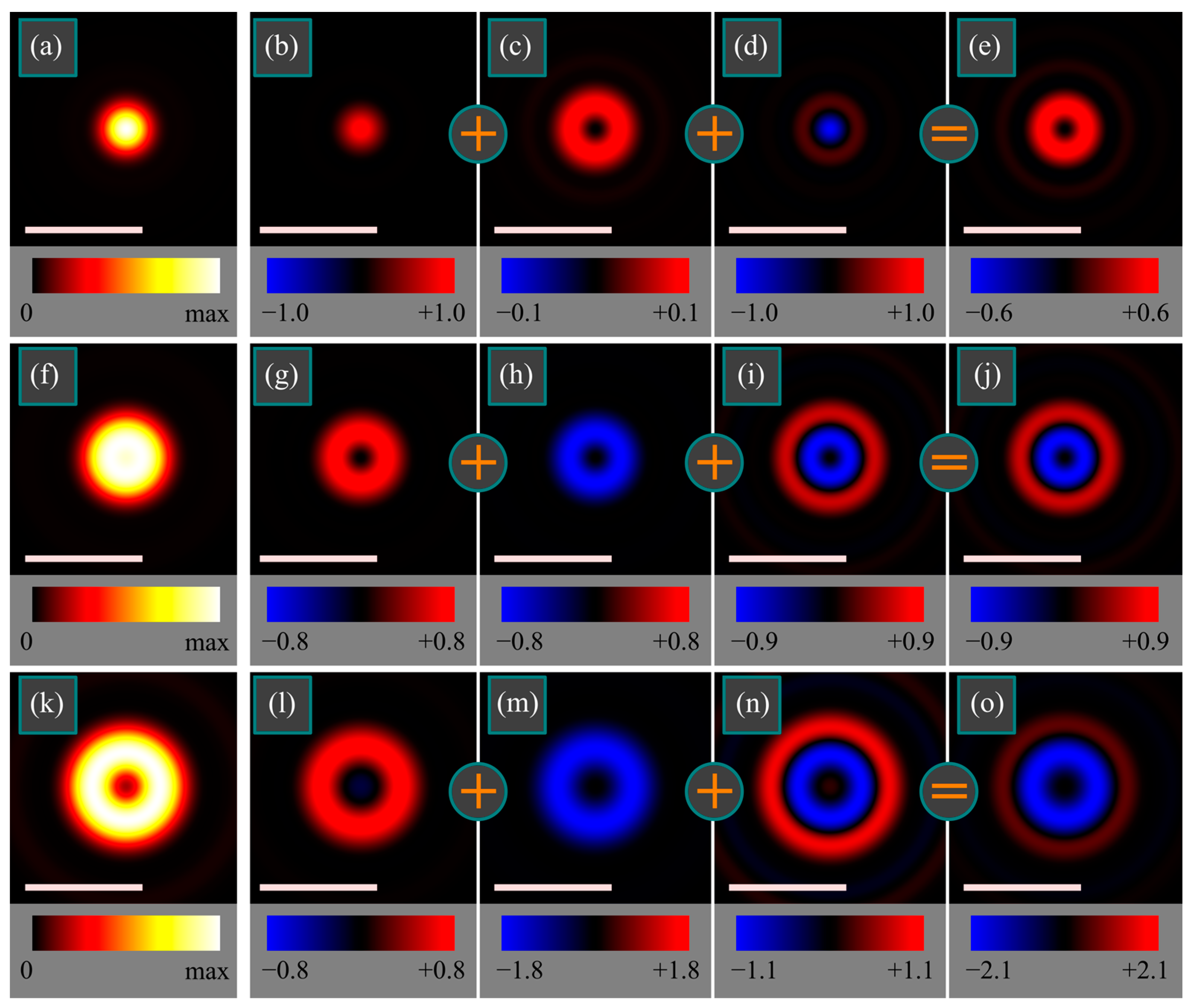
Figure 1 illustrates the intensity distributions
I (4), as well as the distributions of the longitudinal components of the SAM
Sz (10), OAM
Lz (14), second term in Equation (29), and full AM
Jz (12) in the tight focus of a vortex field with right circular polarization and homogeneous unit initial amplitude
A(
θ) = 1 (1) for
n = 0, −1, −2 in the following parameters: wavelength
λ = 532 nm, focal length of the focusing lens
f = 10 μm, numerical aperture NA = sin
θ0 = 0.95, computation domain 2 μm × 2 μm. Distributions of the SAM, the OAM, the second term in Equation (29), and the full AM are normalized to maximal intensity, and the corresponding maximal magnitudes of each quantity are shown in the legend below each figure.
As seen from
Figure 1f–j, at
n = −1, the SAM (10) and the OAM (14) indeed compensate for each other; their sum is zero, and the total AM (12) consists of only one component equal to the second term in Equation (29). At
n = −2 (
Figure 1k–o), the SAM (10) and the OAM (14) are similar by shape but no longer compensate for each other; the OAM is greater by magnitude and thus contributes to the total AM, along with the component defined by the second term in Equation (29). This component includes an inner light ring with a negative AM density and an outer ring with a positive AM density. Due to the summation with the OAM, the outer ring in the total AM is weaker than the inner one. At
n = 0 (
Figure 1a–e), the SAM has the shape of a spot, while the OAM has the shape of a ring, and they are both positive. The component defined by the second term in Equation (29) contains a central spot with a negative AM and a ring with a positive AM. The central spot compensates for the SAM, whereas the ring with the positive AM is summated with the positive OAM, thus generating a ring-shaped distribution of the total positive AM. Therefore,
Figure 1 indicates that the summary longitudinal AM component (integrated over the beam cross-section) is positive at
n = 0 (
Figure 1e) and will rotate a nearly 1-μm-sized particle with a center on the optical axis counterclockwise. The summary longitudinal AM component at
n = −2 is negative (
Figure 1o) and will rotate a small particle clockwise. We note that initial polarization of the field (1) is right-handed, and the polarization vector rotates counterclockwise. Nevertheless, the particle in the focus should be rotated clockwise. The summary longitudinal AM component at
n = −1 is almost zero (
Figure 1j), and, therefore, a small particle placed into the focus with its center on the optical axis will not be rotated.
9. Conclusions
In this work, based on the Richards-Wolf formalism, simple analytical expressions have been derived for the longitudinal component of the AM density vector (12) of light in the focus of an optical vortex with a topological charge
n and with right circular polarization. In addition, expressions for the SAM (10) and for the longitudinal OAM component (14) have been obtained. We have demonstrated that the sum of the SAM and OAM densities is not equal to the AM density. It has been shown previously that the sum of only the total (integrated over the whole space) SAM and OAM is equal to the total AM of the light beam (23). We have also shown in a general form that the AM density is equal to the sum of three terms (29): the SAM, the OAM, and a certain third term that does not contribute into the total AM (23). It is also shown in this work that the expressions (2) for the strength vectors of the electric and magnetic fields near the tight focus, derived by using the RW formalism, are exact solutions of Maxwell’s Equations (31)–(33). Thus, the RW theory exactly describes the behavior of light near the tight focus in free space. The simulation results (
Figure 1) agree with the theoretical outcomes. The obtained results can be used for correct design of optical traps, in which the light field should govern both the procession of particles along some trajectories and their rotation around the centers of mass. Thus, both the OAM and the SAM densities should be correctly tailored in such traps. In this work, we limited our studies to theoretical considerations and numerical computations. For experimental confirmations, the SAM can be measured by using polarizers [
28], while the OAM can be determined using cylindrical lenses [
29,
30] or by computing the intensity moments [
31,
32].


