1. Introduction
Beam scanning technology refers to the technology of accurately controlling and positioning the beam direction, which is often used in the fields of laser radar, optical information processing, and free space optical communication. Beam scanning technology can be divided into mechanical scanning, micro-electromechanical scanning, and purely electronic, non-mechanical scanning. Today’s development trend is to focus on the research and development of a beam scanning system that integrates a large scanning angle, high precision, fast response, and high efficiency. At the same time, in order to facilitate integration and military and civilian applications, the system also needs to be more compact and flexible, and the manufacturing process needs to be simple. As for the current situation, the microlens array has the potential development space to achieve the above characteristics, with a small beam pointing deviation and a high scanning rate. In this paper, the method of beam scanning through the double-layer microlens array belongs to micro-electromechanical systems (MEMS) scanning [
1]. Microlens arrays are widely used in the fields of optical imaging detection, laser radar, and optical communication, owing to their small beam-pointing deviation, high scanning rate, and fast steering during dynamic imaging [
2,
3,
4], and the fabrication process of microlens arrays is gradually improving [
5,
6,
7]. The lightweight and small motion characteristics of microlens arrays mean that, compared with macro lenses, they can greatly simplify mechanical parts to achieve beam steering. However, as the scanning angle increases, beam crosstalk can occur between microlens array units, that is, some light will be superimposed on the imaging light of adjacent units and will therefore participate in adjacent imaging, which interferes with normal light transmission; this is called a crosstalk beam, and its occurrence reduces the imaging contrast of an imaging system.
Many researchers have proposed a variety of solutions to the crosstalk problem in different situations. In 2004, researchers made an objective lens array and a collimating lens array on the same substrate, so that the first side of the second row could be used as a field mirror and the arrays could move in the same way to achieve crosstalk-free beam imaging. When scanning with visible light, a beam deflection of 3–7.4° and a transmission efficiency of up to 13% can be achieved compared with that of single-sided scanning [
8]. In 2018, researchers at Tianjin University designed a transceiver microlens array system that used optical wedges to switch the field of view so that there was no crosstalk between the fields of view, and it was combined with the front and rear objective lenses to realize beam scanning with a scanning field angle of ±8° and an instantaneous field angle of ±1.06° [
9,
10]. In the same year, researchers at a laboratory in Beijing proposed a method of combining aperture and microlens arrays to eliminate crosstalk; they studied the instantaneous field of a microlens array at a limited object distance and achieved high-quality imaging [
11]. The propagation path of stray light can also be blocked using a field aperture, a Lyot stop, and the ‘no-shelter’ optical design [
12,
13].
Aiming at the problem of crosstalk beam in the application of microlens array scanning imaging, focus on the research on the crosstalk influence mechanism of microlens array, combine the microlens array imaging theory, carry out the research on the influence of the crosstalk beam between arrays based on geometric optics and diffraction effect, and build the stray light analysis model. According to different situations, the size, filling ratio, and aperture of the microlens unit should be correctly selected, and the optimal relationship between the entrance pupil diameter and the exit pupil diameter of the microlens array unit should be studied to provide support for the stray light suppression and optimization design of the microlens array. In the past period of time, our team members have carried out research on some of these problems, such as proposing a filling factor to characterize the relative aperture and analyzing its impact on the modulation transfer function. The filling factor is calculated by matrix optical paraxial ray tracing using system parameters [
14]. Based on the principle of minimum spherical aberration, the design method of the initial configuration of the MLA system is proposed, and the influence of the MLA system on detection range and imaging resolution is analyzed [
15,
16]. Aiming at the problem of obvious diffraction when light encounters small diameter components in the transmission process, the diffraction effect of microlens arrays is analyzed, and different types of aperture arrays with the same filling factor are given through geometric relationships and system parameters. The light intensity distribution forms are compared, the diffraction effect of aperture array forms on imaging quality is explored, and a more advantageous structural form is selected [
17].
Due to the off-axis caused by the relative displacement of the double-layer microlens array in the process of movement and the discontinuous characteristic sampling of the array, the crosstalk beam of the microlens array system presents obvious nonlinear dynamic degradation characteristics with the increase in the search field of view, so it is necessary to study the mechanism and control methods of crosstalk beams. The existing micro-optical array imaging theory and optimization methods make it difficult to study the dynamic imaging characteristics of the stacked microlens array system. It is necessary to improve its dynamic imaging theory and modeling methods, improve the ability to control and suppress crosstalk during dynamic scanning, and break through the design method of the stacked microlens array for search imaging. In this paper, we refer to the research methods of other researchers and the work completed by the team members, combined with the above solutions, to consider the crosstalk problem when the dynamic scanning imaging object distance of a microlens array is infinite. Through analysis of the crosstalk mechanism, we propose a design of multilayer stop arrays combined to suppress crosstalk beams and consider an example scanning imaging system to verify the correctness of the proposed method, which provides a basis for crosstalk suppression design methods for other systems.
2. Crosstalk Beam Generation Mechanism
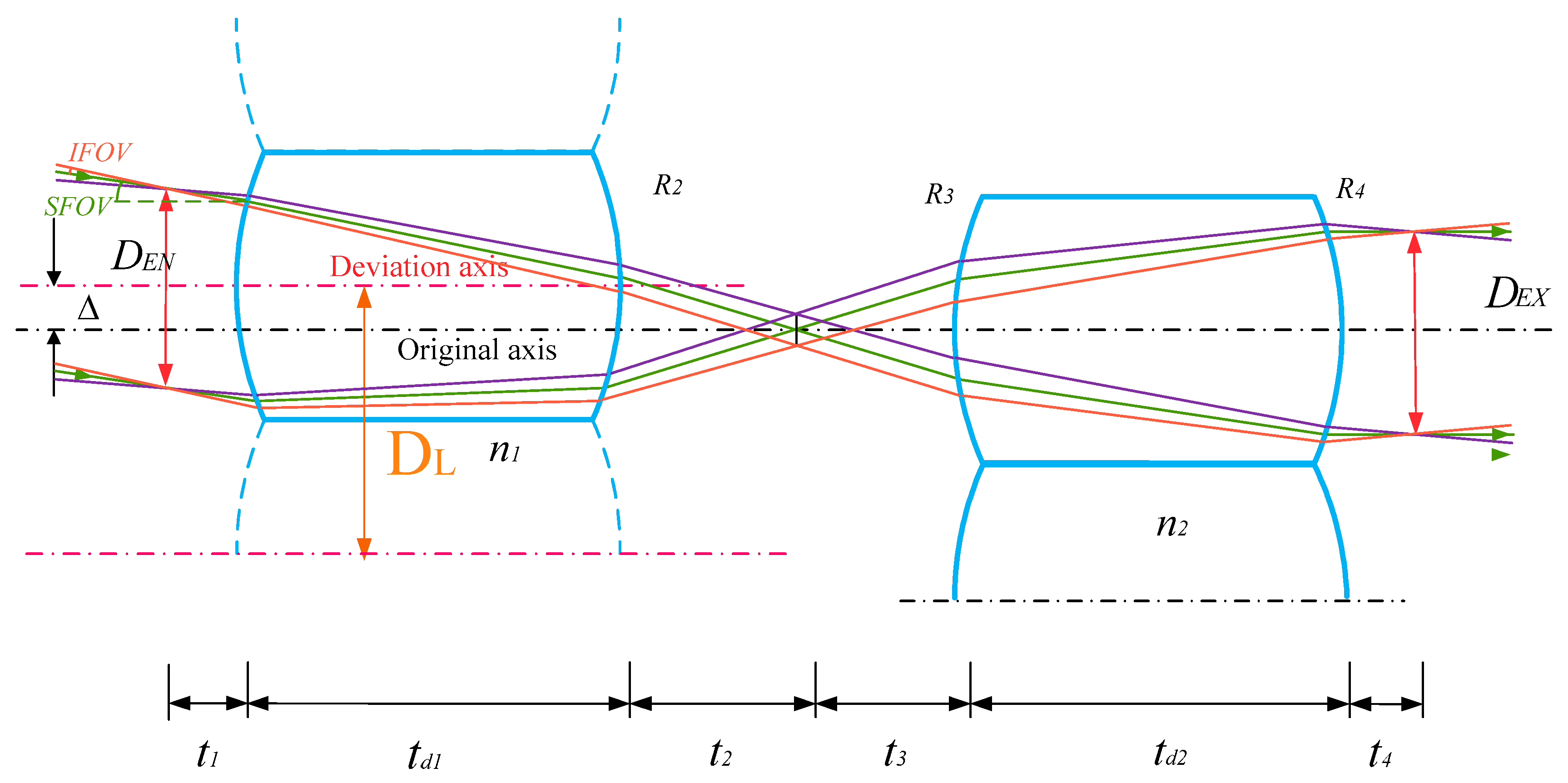
A microlens array is composed of lenses with small diameters arranged according to certain rules [
18]. In this paper, we discuss a double-layer microlens array system; the field of view of this system is determined by both the instantaneous field of view (IFOV) and scanning field of view (SFOV). Hence, under the premise of ensuring maximum light energy utilization and to achieve a wider range of scanning, the first column of the microlens array is used for relative movement, and the second column and rear component are fixed. Beam deflection can be achieved by using the relative displacement of the two columns. Additionally, the rear focus of the first column coincides with the front focus of the second column; when the beam is incident on the system at an oblique parallel angle, the beam is emitted parallel to the optical axis through displacement, and different scanning angles correspond to different displacement
[
19], as shown in Equation (1). IFOV and SFOV form the field of view of the microlens array system. As shown in
Figure 1, fast scanning can be completed by using different fields of view of the system. The displacement of the system is given by
where
is the focus of a single microlens, and
is the scanning angle.
We define the width of the entrance pupil of the system as , the width of the exit pupil of the system as , radius of curvature of each lens surface as (, , , ), thickness of each lens center as (,), refractive index of each lens as ( ), and lens diameter as , the distance between the entrance pupil and the first surface as , the distance between the second surface and the primary image plane as , the distance between the primary image plane and the third surface as , and back intercept as .
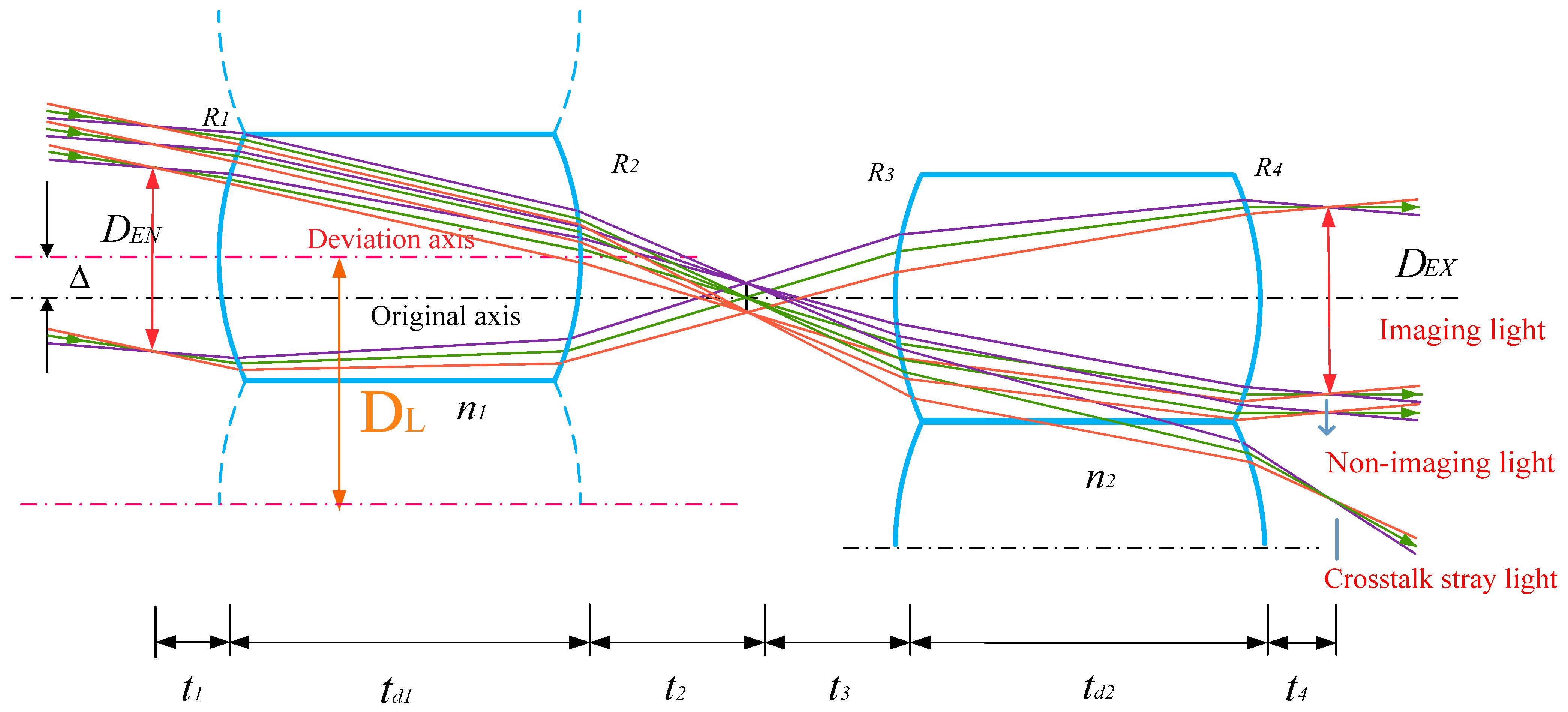
However, the scanning process of the optical system has a large eccentricity or large angle of incidence.
Figure 2 shows a schematic of the crosstalk generated by the proposed double-layer microlens array, based on the Kepler structure. At this time, not all incident light refracted by the first column micro lens array will enter the lens unit corresponding to the second column micro lens array, however, part of the light will continue to propagate to the adjacent lens, interfering with the normal imaging beam; this is defined as a crosstalk beam. The area
is an imaging ray. After system imaging, this area is
. The ray from the lower edge of
to the lower edge of the lens represents a non-imaging ray that remains in the corresponding array aperture. When the incidence angle of the ray changes, the non-imaging light can be converted to a crosstalk ray.
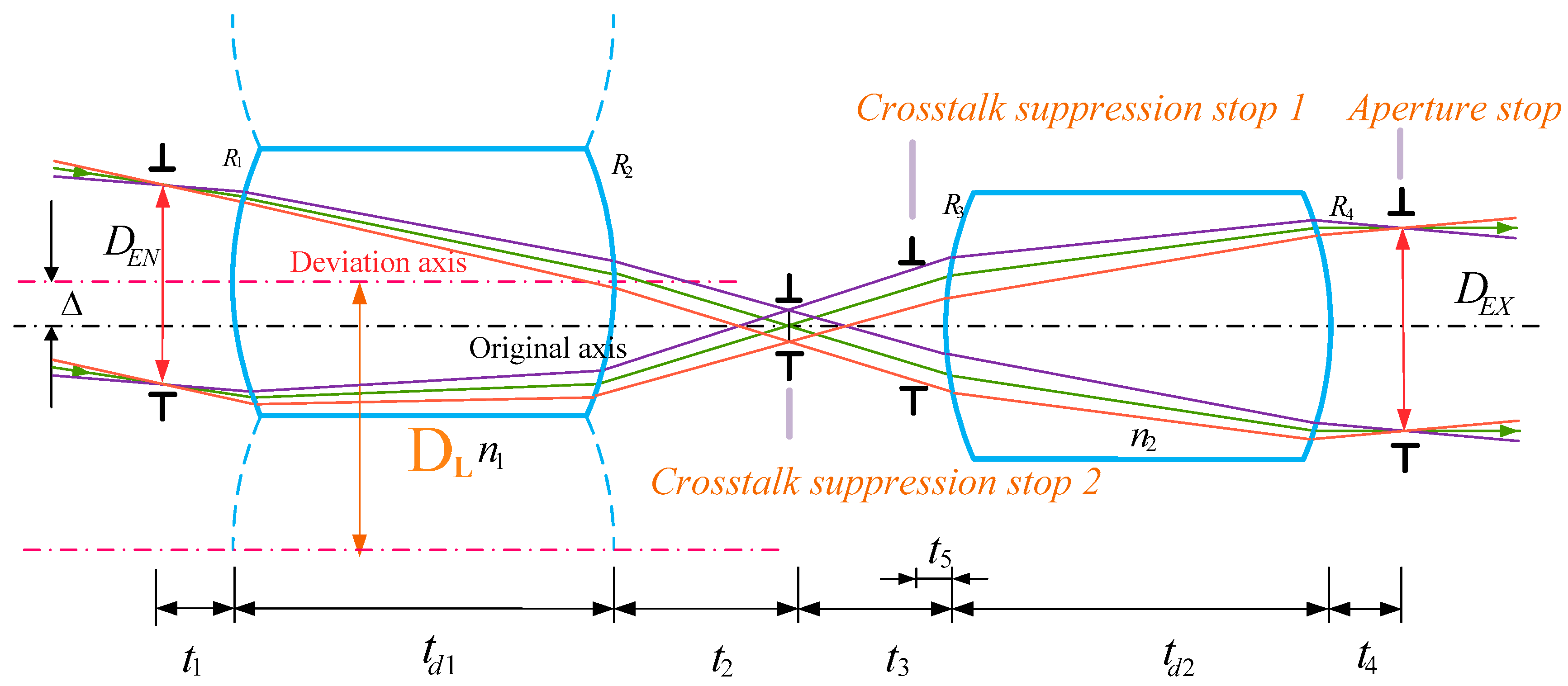
3. Crosstalk Suppression Design of Multilayer Stop Arrays Combination
Based on the discussion of the mechanism of crosstalk generation in
Section 2, we propose a design method of a combination of multilayer stop arrays to eliminate crosstalk. In the process of light transmission, we can effectively isolate the crosstalk beam by reasonably setting the stop form.
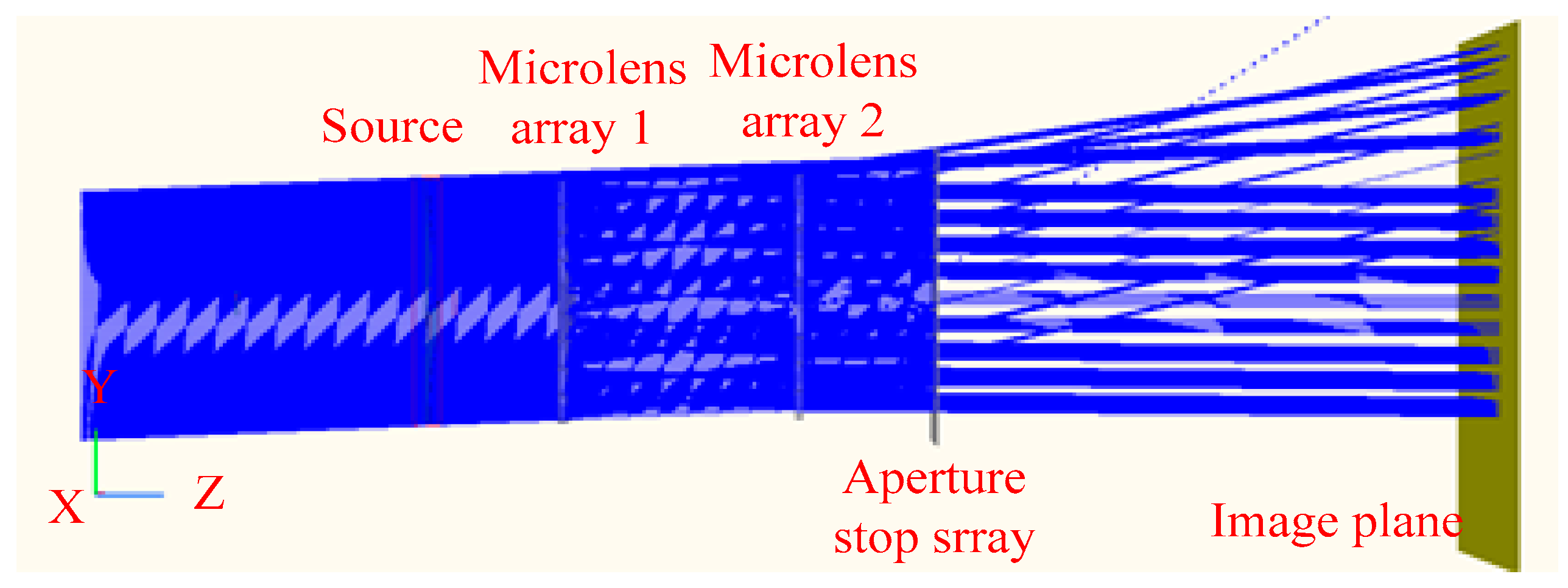
We consider three aspects. First, a microlens array system is usually combined with an infrared optical system for imaging. The microlens array system has an aperture stop array at the exit pupil, which is where the imaging beam exits the system, as shown in
Figure 3; additionally, the aperture stop array prevents the light in the non-imaging area from spreading to the image plane, effectively isolating the non-imaging beam.
Second, a crosstalk beam enters the image plane through the exit pupil, which interferes with the imaging of normal light and reduces the contrast of the image. If the energy of the crosstalk beam is too large, it can make it difficult to distinguish between the target and background and, therefore, difficult to extract useful information. Therefore, we set the first crosstalk suppression stop array at a certain distance from the front surface of the second column of the microlens array to limit the crosstalk beam during light transmission and effectively block stray light, as shown in
Figure 3.
Finally, as the array scanning imaging system has an IFOV, the two columns of the microlens arrays form a focus-free system; the back focus surface of the first column of lenses is used as the front focus surface of the second column of lenses. Therefore, a second crosstalk suppression stop array is necessary at the primary image plane between the two arrays to control the number of imaging rays under multiple fields of view and limit the mixing of light outside the field of view. The light transmission is controlled by adjusting the position and size of this array.
To summarize, the aperture stop array and the two crosstalk suppression stop arrays form a multilayer stop array to realize crosstalk elimination. Through multilayer suppression, beams reaching the image plane can avoid interference from crosstalk beams and achieve high-precision imaging.
4. Parameter Calculation of Multilayer Stop Arrays
As shown in
Figure 3, our initial structure is composed of two positive power microlenses; this is used as a model for analysis and discussion in this paper. To determine the specific location and aperture size of the crosstalk suppression stop arrays, calculations must consider ray tracing in geometric optics and the relevant theory of the Gaussian formula. According to these parameters, the exit pupil
can be calculated using the Lagrange invariant in Equation (2):
According to the theory of geometrical optics, the distance
and
can be determined using a Gaussian equation for the two lenses; hence, the position of the crosstalk suppression stop array 2, between the double-layer microlens arrays, can be determined by
where
n and
are the refractive indexes of each medium,
l and
are the object and image distances, respectively, and
R is the radius of curvature of the lens surface.
By calculating
and
(
Figure 3), we obtain
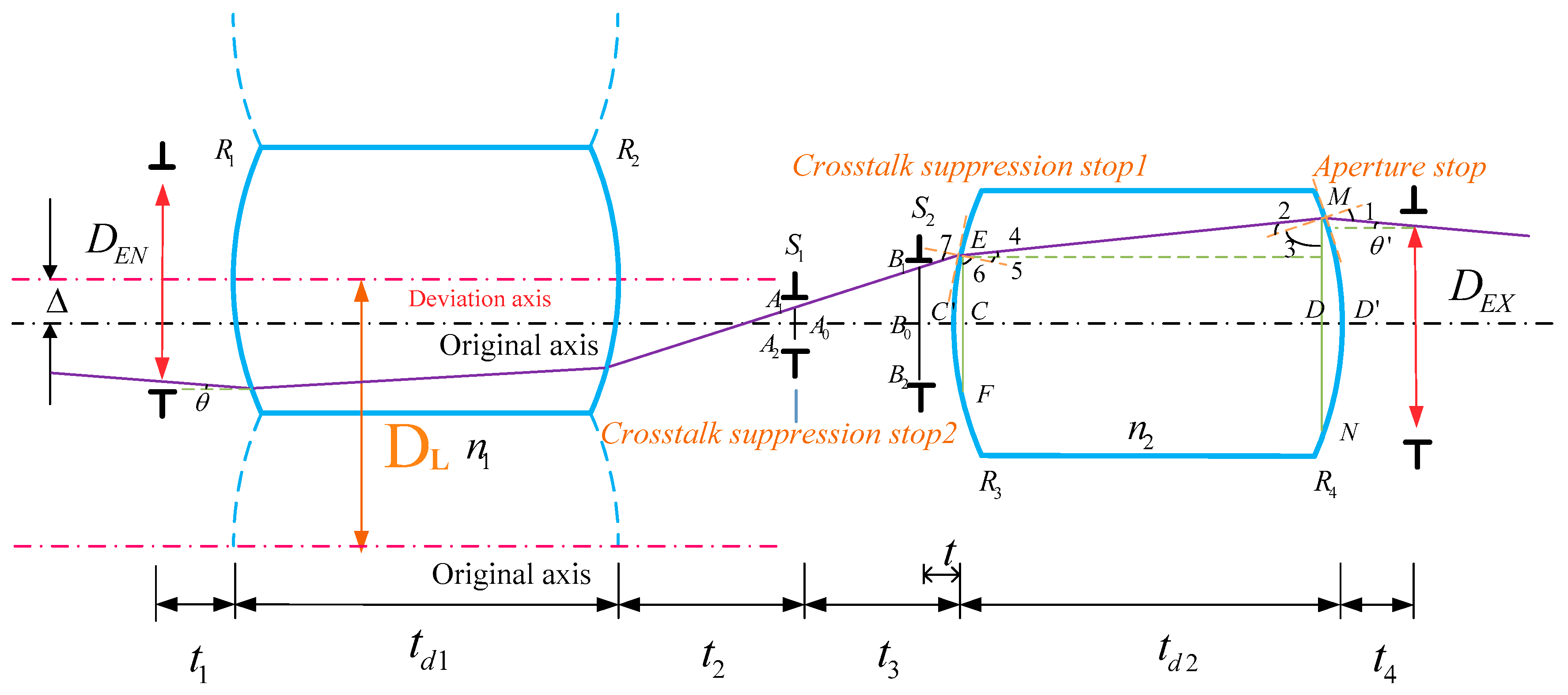
After determining the position of the crosstalk suppression stop array 2, reverse ray tracing is performed on the edge ray of the optical system that is incident at a non-zero field of view. As shown in
Figure 4, the oblique parallel light enters the microlens array at an angle of
θ and exits at an angle of
. Therefore, the aperture sizes of both crosstalk suppression stops can be calculated by tracing the reverse optical path, according to IFOV, to ensure that no stray light leaks into the normal imaging optical path.
Expressions of each part of the refracted light ray in
Figure 4 can be obtained:
Equation (11) can be obtained according to the refraction law
We define the distance between the crosstalk suppression stop 1 and the front surface of the second row of the microlens array as
t; then, the above steps are repeated to calculate the aperture size of the crosstalk suppression stop 1, which is given by Equation (12):
Similarly, the aperture size of the crosstalk suppression stop 2 is given by Equation (13):
The size and position of each stop array can be approximated by the above method of reverse tracking the edge light, which provides theoretical support for our design of light elimination. As the above calculations are carried out without considering aberration, an appropriate allowance should be made for the size of the optical aperture to ensure that light can be stably transmitted between the corresponding microlens array units and stray light is prevented from entering the adjacent microlens units to ensure that the incident light can participate in the imaging to a greater extent during system simulation and actual design.
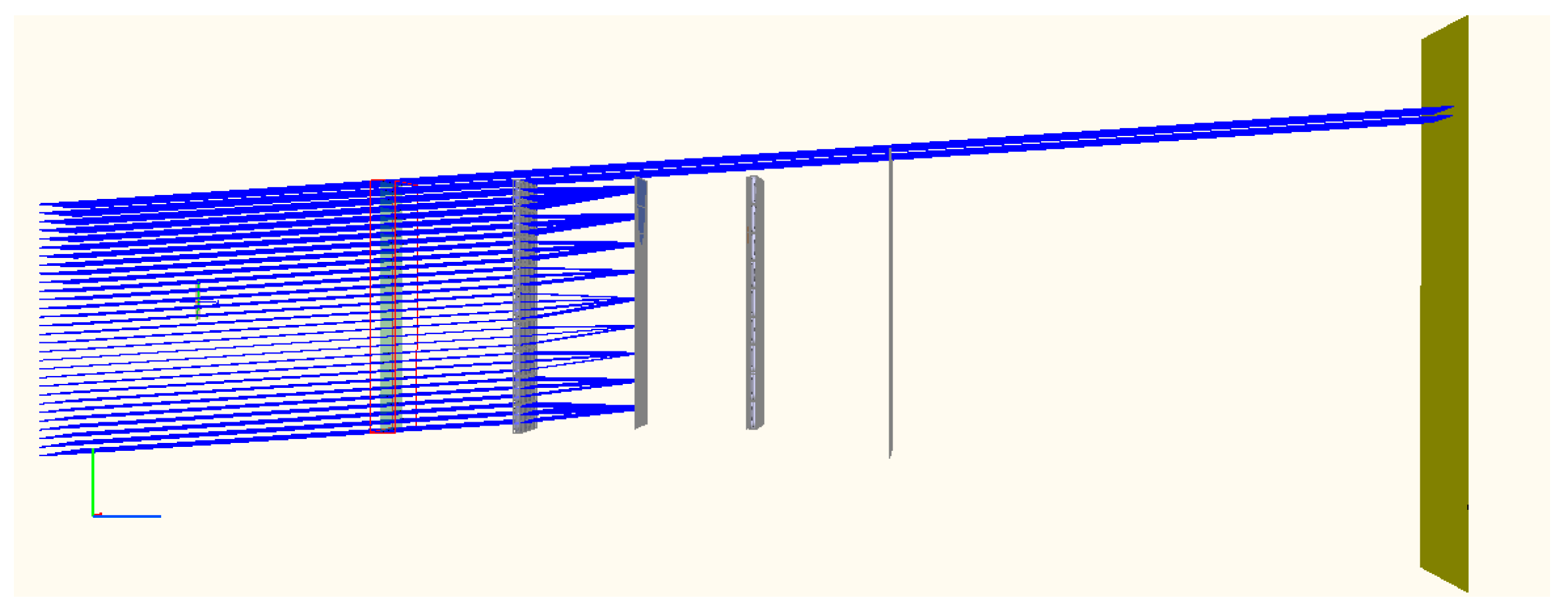
5. Case Analysis
We consider an example microlens array scanning imaging system to explain the theoretical aspects outlined in
Section 2,
Section 3 and
Section 4.
Table 1 details the parameters of the system.
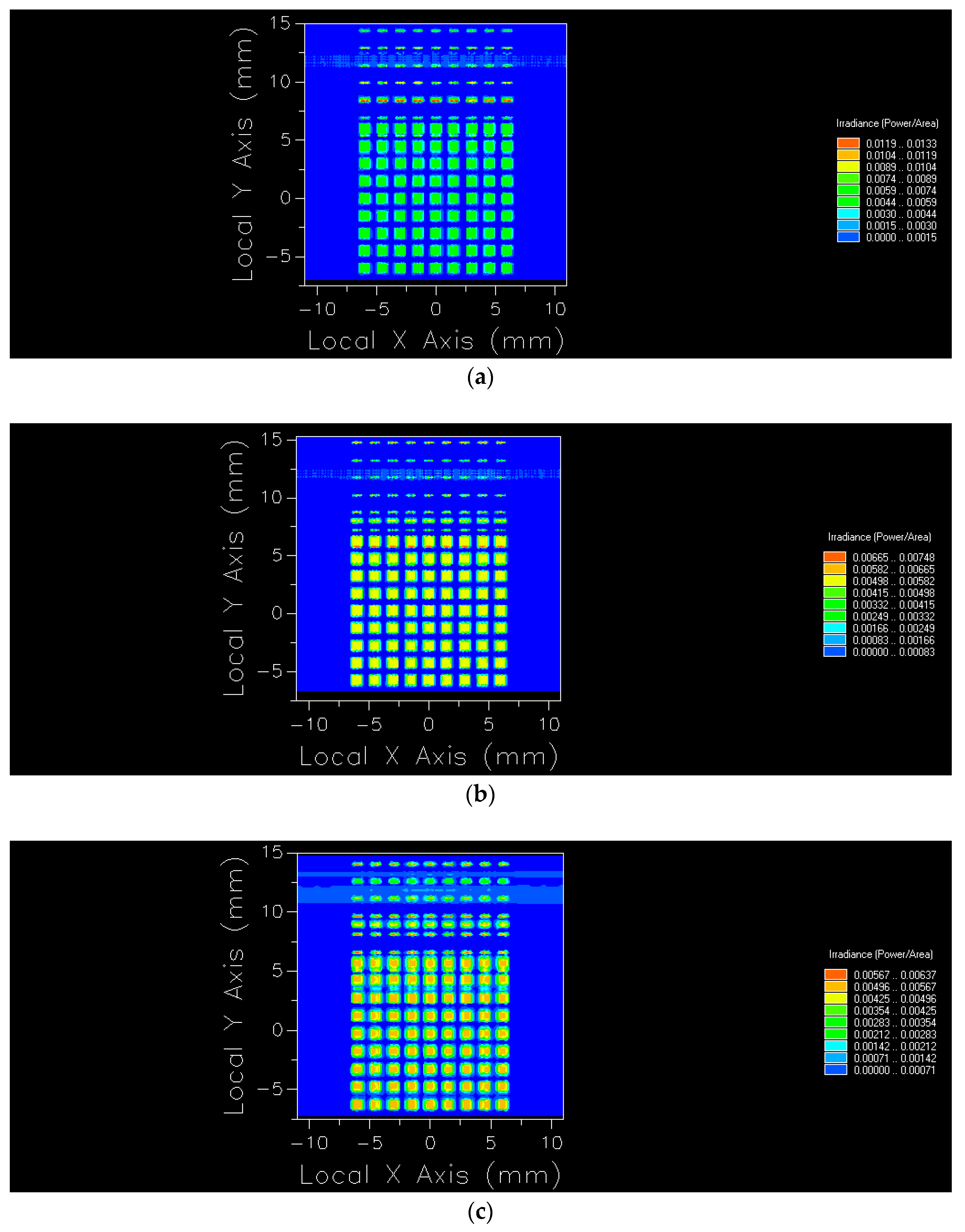
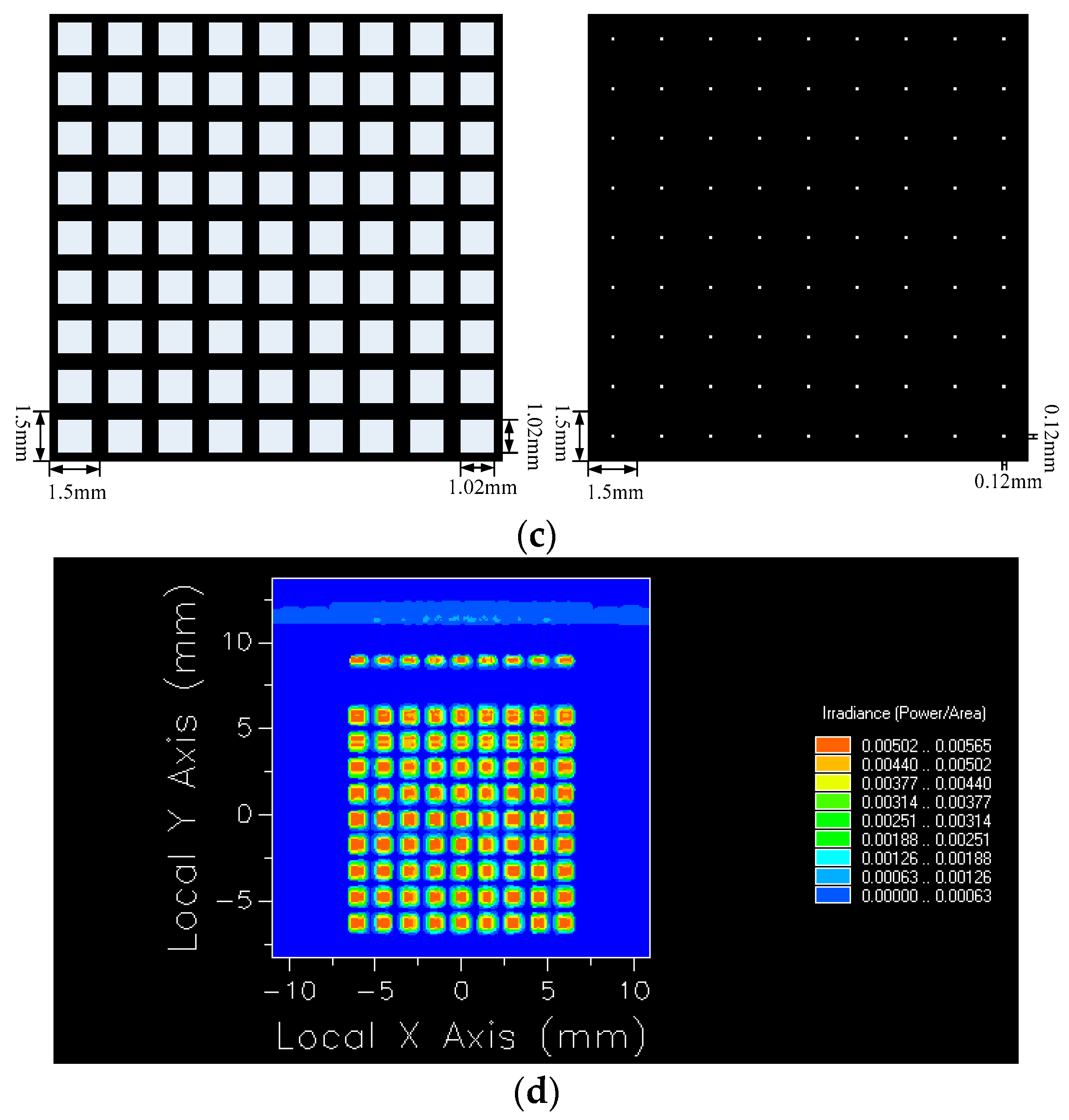
Figure 5 shows a microlens array scanning imaging system that works in the mid-infrared band, and it was built using the optical software Fred to trace a small amount of light and simulate the above parameters. Two rows of 9 × 9 rectangle microlens arrays made of germanium are arranged. Scanning imaging is achieved through the relative displacement between the arrays. However, the crosstalk beam generated by the system during the scanning process interferes with the normal imaging optical path. As an example, we use Fred to simulate the crosstalk phenomenon of the microlens array with only an aperture stop array and no crosstalk suppression stop arrays when the microlens array is staggered along the Y axis and SFOV δ is −2°, IFOV
is 0° and ±0.5°, as shown in
Figure 5.
As the array is a periodic structure, the generated crosstalk beams also exit in a periodic and parallel manner, passing through the exit pupil and shining on the image plane, interfering with the normal imaging beam and causing image points to be overlapped and difficult to distinguish.
Figure 6 shows images on the plane corresponding to different IFOV
values when the same SFOV δ is −2°.
At the same time, since the microlens array is a two-dimensional dynamic scanning in device the working process, the crosstalk beam can affect the normal beam of the aperture at different positions.
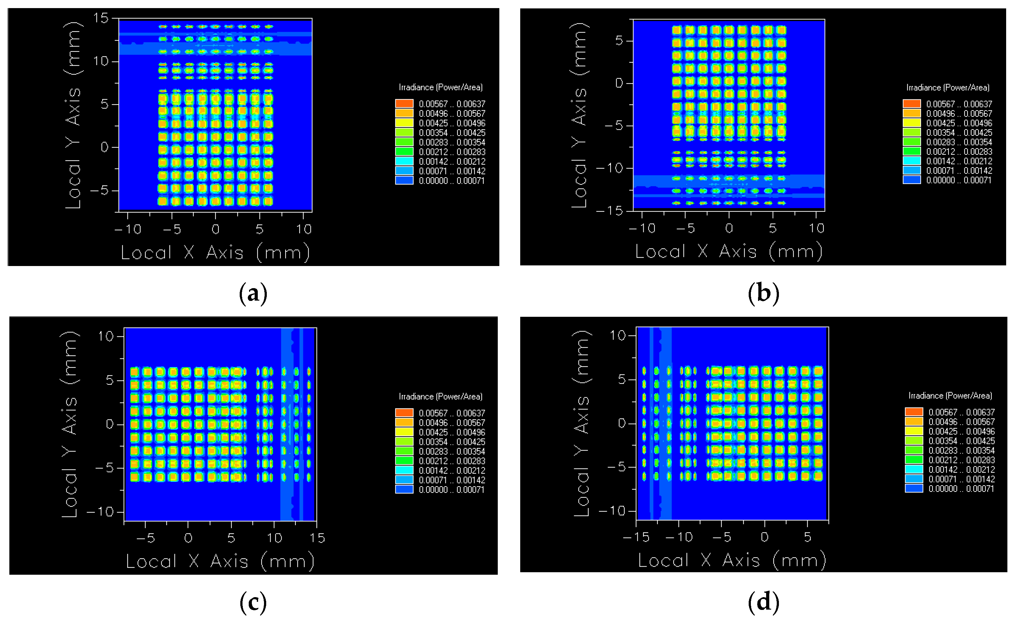
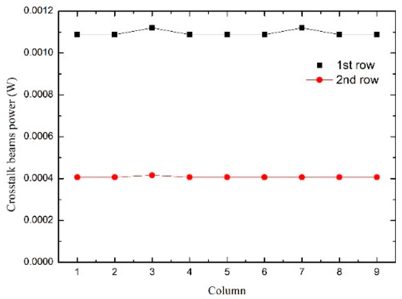
Figure 7 shows imaging diagrams under four characteristic situations when the microlens array is relatively displaced along the X or Y axis.
We take
Figure 7a as an example, and get the energy of each aperture by advanced ray tracing with Fred, as shown in
Table 2.
From the comprehensive consideration of the data in
Table 2 and
Figure 7a, it can be seen that the data in the first two rows in
Table 2 is significantly higher than that in other rows because of the crosstalk beam. When the amount of simulation light increases, the image points of an increased number of crosstalk light beams will be alternately arranged with the image points from the imaging light beams on the image plane and distributed in multiple positions on the image plane, affecting the contrast. Therefore, the crosstalk suppression stop array 1 should be placed on the front surface of the second column of the microlens array to eliminate crosstalk at the design level and block the propagation path of the crosstalk beams.
The previous discussion about the light transmission was for SFOV δ was −2° and IFOV
was 0° and ±0.5°. So as not to change the system structure or parameters, we only adjust the light incidence angle to −4°, keep δ at −2°, and increase
to −2°. The results when the simulation lens is completely transmitted are shown in
Figure 8. The crosstalk suppression stop array 2 effectively blocks light from outside the field of view. For the reason that the aperture size of the crosstalk suppression stop array 2 is calculated according to IFOV, which restricts the incident angle of light together with SFOV, it means that when the light source is incident at multiple angles, and the values of some of the incident angles are not within the limited range, the crosstalk suppression stop array 2 will block them, preventing light from outside the field of view from leaking into the normal imaging optical path.
At the same time, because the microlens arrays are not fully transmissive, ghost reflections occur on the surface of the lenses, and stray light from outside the field of view is generated from all angles. The crosstalk suppression stop array 2 will also block such stray light to prevent it from entering the subsequent optical path and affecting the imaging.
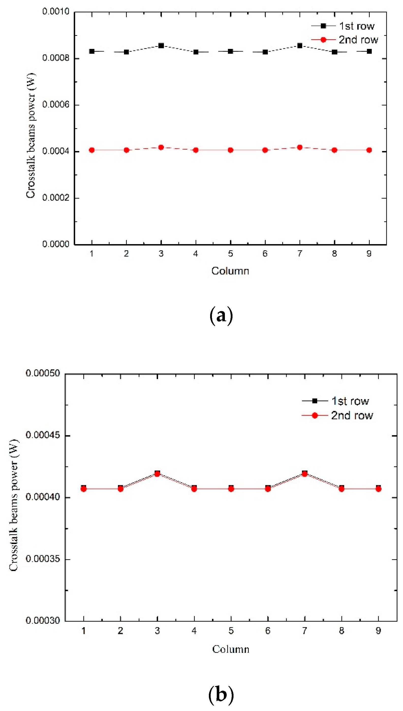
Combined with the above theory, multilayer stop arrays are added to the system to re-simulate it. The results are shown in
Figure 9 and
Table 3.
The image in the top line of
Figure 9d is caused by the light source being directly incident on the system. Compared with
Figure 6c, the system in
Figure 9d has no crosstalk beams, and the power values of each aperture in
Table 3 are uniformly distributed.
Therefore, the power value of the crosstalk beams interfering with the first and second row aperture stop arrays can be given according to the data in
Table 2 and
Table 3, as shown in
Figure 10.
Similarly, through simulation and calculation, the crosstalk power under “Y axis, δ = −2°,
= 0°” and “Y axis, δ = −2°,
= 0.5°” can be given, as shown in
Figure 11.
After adding the crosstalk suppression stop arrays, the crosstalk beam is blocked and will not appear on the image plane. The crosstalk-free imaging of the microlens array system with a SFOV of 4° × 4° and an IFOV of 1° × 1° is realized without an external lens.
We use the optical simulation software Fred to analyze the tolerance of crosstalk suppression stop arrays 1 and 2 in the system. The positioning tolerance is shown in
Table 4.
As shown in
Table 4, it is the positioning tolerance of two crosstalk suppression stop arrays on different optical axes. Since two-stop arrays correspond to different positions and parameters, their allowable variations on the reference position are also different.
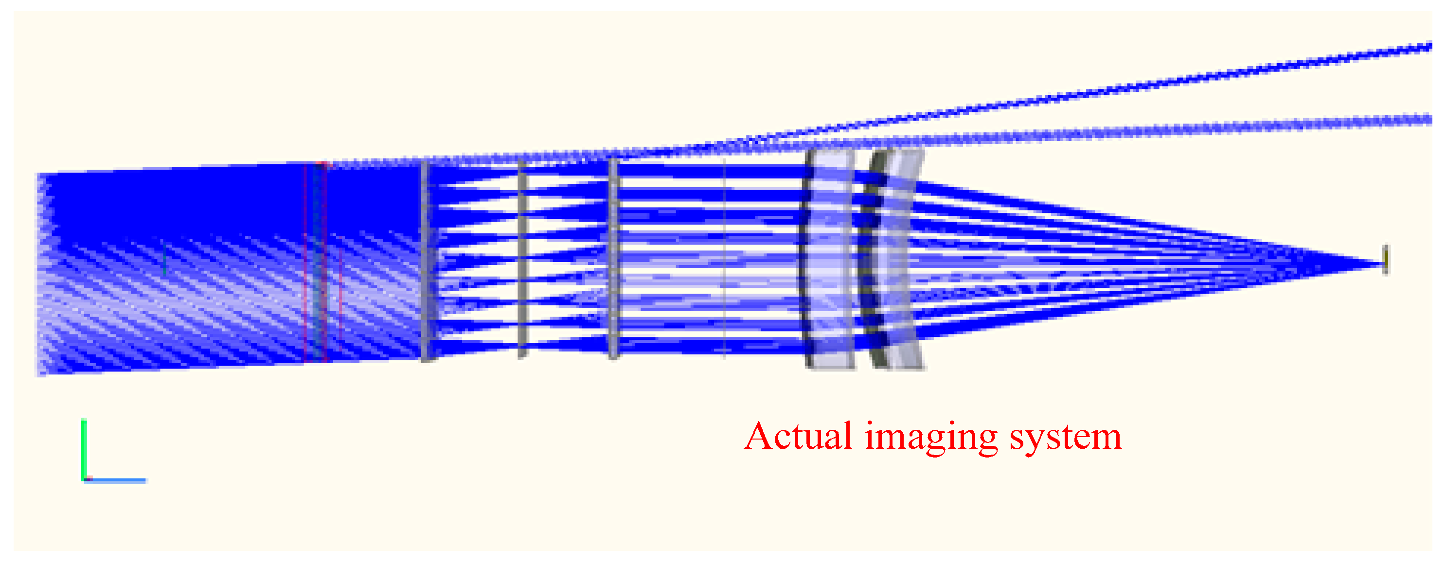
Generally, the microlens array is connected to the actual imaging system. Therefore, according to
Figure 9a, we add the actual imaging system behind the aperture stop array, as shown in
Figure 12.
According to the optical system of
Figure 12,
Table 5 shows the imaging conditions for different values of SFOVand IFOV.
Figures in
Table 5 correspond to different SFOVs and IFOVs, and the RMS size is within one pixel, so its aberration is acceptable. At the same time, because the system needs to perform dynamic scanning and imaging in the infrared band, it is difficult to achieve perfect imaging in the full medium wave section. However, for this system, we have expanded the wavelength by 3.8–4.2 μm, and its images are shown in
Table 6, where the red color is 3.8μm, the blue color is 4.0 μm, and the green color is 4.2 μm.
It can be seen from
Table 6 that, on the premise of considering both imaging results and beam scanning, the 3.8–4.2 μm wave band light is imaged through the system for non-crosstalk imaging, and all sizes of the image point are smaller than one pixel size, and the aberration is acceptable.
In summary, in the simulation of an actual optical system, multiple stop arrays can be used to cooperate with one another to suppress crosstalk beams layer by layer, maximizing the isolation of crosstalk beams in the system. Compared with the single-layer stop array suppression method, the proposed multilayer stop array crosstalk elimination design method improves the suppression of crosstalk beams and effectively suppresses other stray light, such as ghost reflection light.


