1. Introduction
At present, as an indispensable part, magnetic field sensors have been widely used in scientific research, production, and life areas such as military, geospatial physics, industrial manufacturing, and biomedicine [
1,
2,
3,
4,
5,
6]. With the increasing development of technology, magnetic field sensors are capable of detecting magnetic fields ranging from
f-Tesla to k-Tesla.
As one of the most important categories, fiber-optic magnetic field sensors (FOMSs), has drawn more and more attention due to their natural advantages of anti-electromagnetic interference, high resolution, excellent stability, and integration. The existing fiber-optic magnetic field sensors, which can be divided into four types, commonly have difficulties to achieve high sensitivity, high stability, and miniaturization simultaneously. The first type is based on Mach-Zehnder (M-Z) or Michelson interferometers, which usually utilize the deformation of magnetostrictive materials in the sensing unit caused by an external magnetic field to apply a modulation on the propagating light signal [
7,
8,
9,
10]. However, the stability of such systems is quite poor, as the non-common path interferometric structure is unable to eliminate the noise introduced by environmental factors. The second type normally makes use of magnetic fluid as the sensing element and measures the magnetic field through the change of dip wavelength drift or interference intensity in the Fabry-Perot cavity or interferometers. The major disadvantages of this kind of sensor are low sensitivity, poor stability, and slow response [
11,
12,
13,
14,
15]. The third is based on the Faraday effect [
16,
17]. M. N. Deeter has carried out plenty of research on Faraday magnetic field sensors using high magneto-optical coefficient materials and achieved a sensitivity of
, but the high sensitivity only aims at the AC magnetic field [
17]. The last type is based on some relatively new approaches, including surface plasmon resonance, Lorentz force, atomic magnetometer, and so on, which has the shortcomings of either poor sensitivity and stability or difficulty in miniaturization [
18,
19,
20].
In summary, the existing fiber-optic magnetic field sensors based on the varieties of sensing theories or structures have the following three deficiencies. Firstly, the sensitivity of some schemes is generally low, making it difficult to satisfy high-precision demands. The second is that the reported methods with relatively high sensitivity cannot use common path interference to solve environmental problems, such as polarization instability and phase drift. Last, but not least, the methods based on the Faraday effect have difficulties to realize the accumulation of signal due to the parallel direction of the sensing unit and magnetic field.
Aimed at the problems mentioned above, a fiber-optic all-polarization Sagnac magnetic field sensor is proposed. The Sagnac structure is used for polarization detection, making the system more concise than the phase detection schemes which need quarter-wave plates. Furthermore, the common path Sagnac interference makes it possible for high stability measurement. A high magnetic field sensitivity sensing unit composed of magneto-optic crystal and a specially designed magnetic flux concentrator contributes to achieving high resolution and large dynamic measurements. In the second part of the paper, the overall scheme of the system is proposed, the theoretical model of the light transmission path is established based on the Jones matrix, and corresponding simulation is carried out on the established model. In the third part, an experimental system is demonstrated and its performance is tested. In the last part, the summary is made.
2. System Scheme and Theoretical Model
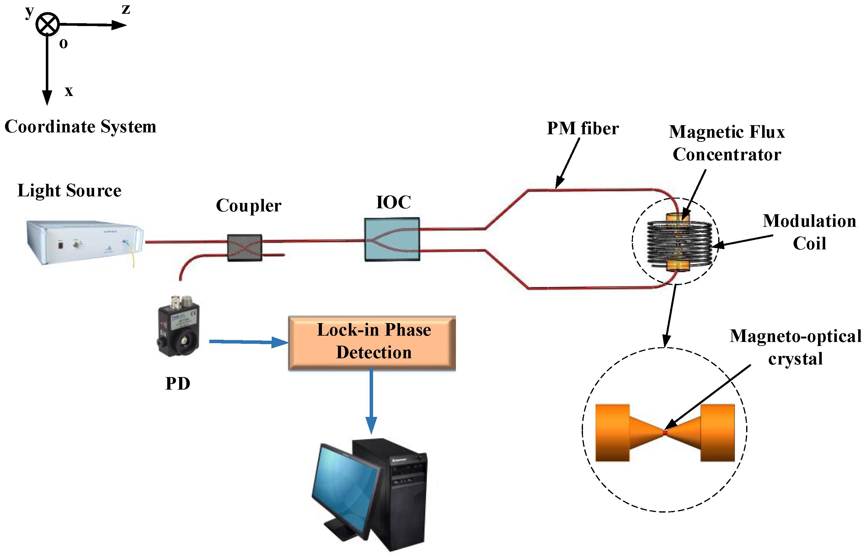
The scheme of the proposed magnetic field sensor system is shown in
Figure 1, which mainly composes of an ASE light source, coupler, integrated optical chip (IOC), sensing unit, modulation coils, and detector, where IOC is used to provide high extinction ratio polarization and beam splitting/combining.
The ASE source, whose polarization is depolarized by a Loyt depolarizer, emits stable power. The optical signal enters the IOC which is composed of a polarizer and a Y-branch after passing through the coupler and is divided into two signals, which propagate in the clockwise (CW) and counter-clockwise (CCW) directions respectively. Then the signals reach the sensing unit, which is combined with a magnetic field concentrator and magneto-optical crystal, shown as the insets in
Figure 1. The simulation and experimental results show that the specifically designed magnetic field concentrator with truncated cone shape and axial through-hole achieves a magnetic field gain of 377 times. The sensing unit is wound with AC coils which are used to provide polarization modulation. Meanwhile, a polarization angle will be generated in the transmitting signal under the influence of the external DC magnetic field to be measured. All the fiber used in this system is polarization-maintaining (PM) fiber. When the CW and CCW light signals travelling along the Sagnac interference path return to the IOC, polarization interference occurs and the interference intensity will be detected by a photodetector (PD). As the DC magnetic field introduces a rotation to the polarization angle of the propagating light due to the Faraday effect, the fluctuation of the detected intensity reflects the rotation angle and finally the magnetic field to be tested. Furthermore, as the two light signals go through the same path, the system possesses the advantage of co-path interference, which can effectively suppress some environmental and system errors caused by temperature, vibration, and so on.
Based on the Jones matrix, the theoretical model of the light path in the proposed system is derived and established. Emitted from the light source, the light beam’s coordinate will successively be rotated by corresponding angles with the transmission process. The two beams separately use their own coordinates and z is always along the transmission direction. In order to simplify the model, the imperfections of the devices and the welding are ignored. Assuming that the initial intensity of the CW and CCW light is normalized to 1, the loss coefficient during the transmission process is equal and is omitted in the derivation.
For CW light, the output signal is expressed as
which can be expanded to be
where
C represents the coupler,
Y represents the IOC,
T represents the PM fiber,
represents the Jones matrix of the sensing unit for CW light,
represents the coordinate transformation matrix,
is the splitting ratio of the coupler, which equals 1/2 in this system,
represents the extinction ratio of the polarizer, L1 and L2 represent the length of the PM fiber connected to the upper and lower arm of IOC,
and
represent the transmission constants of the propagating light on the two main axes of the PM fiber,
represents the Faraday angle caused by both AC and DC magnetic fields,
is the modulation amplitude,
represents the degree of polarization of light signal, which is nearly 1 due to the extremely high extinction ratio of IOC made of LiNbO
3. Equation (2) can be simplified as
For CCW light, the output signal is expressed as
which can be expanded to be
where
represents the Jones matrix of the sensing unit for CCW light. Equation (5) can be simplified as
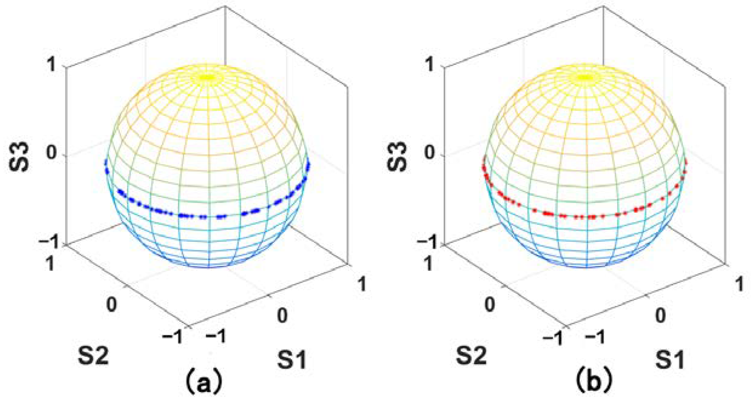
For a more intuitive understanding, the polarization evolution processes of both CW and CCW light are described using the Poincare Sphere and shown in
Figure 2. It can be seen that, with the periodic change of the modulation signal, the output states are all linearly polarized and the polarization angle changes accordingly.
Then the output interference intensity can be written as
when
is quite small, Equation (7) will be converted to be
The magnetic field information can be obtained by performing signal processing through phase lock-in detection.
3. Experiments and Discussion
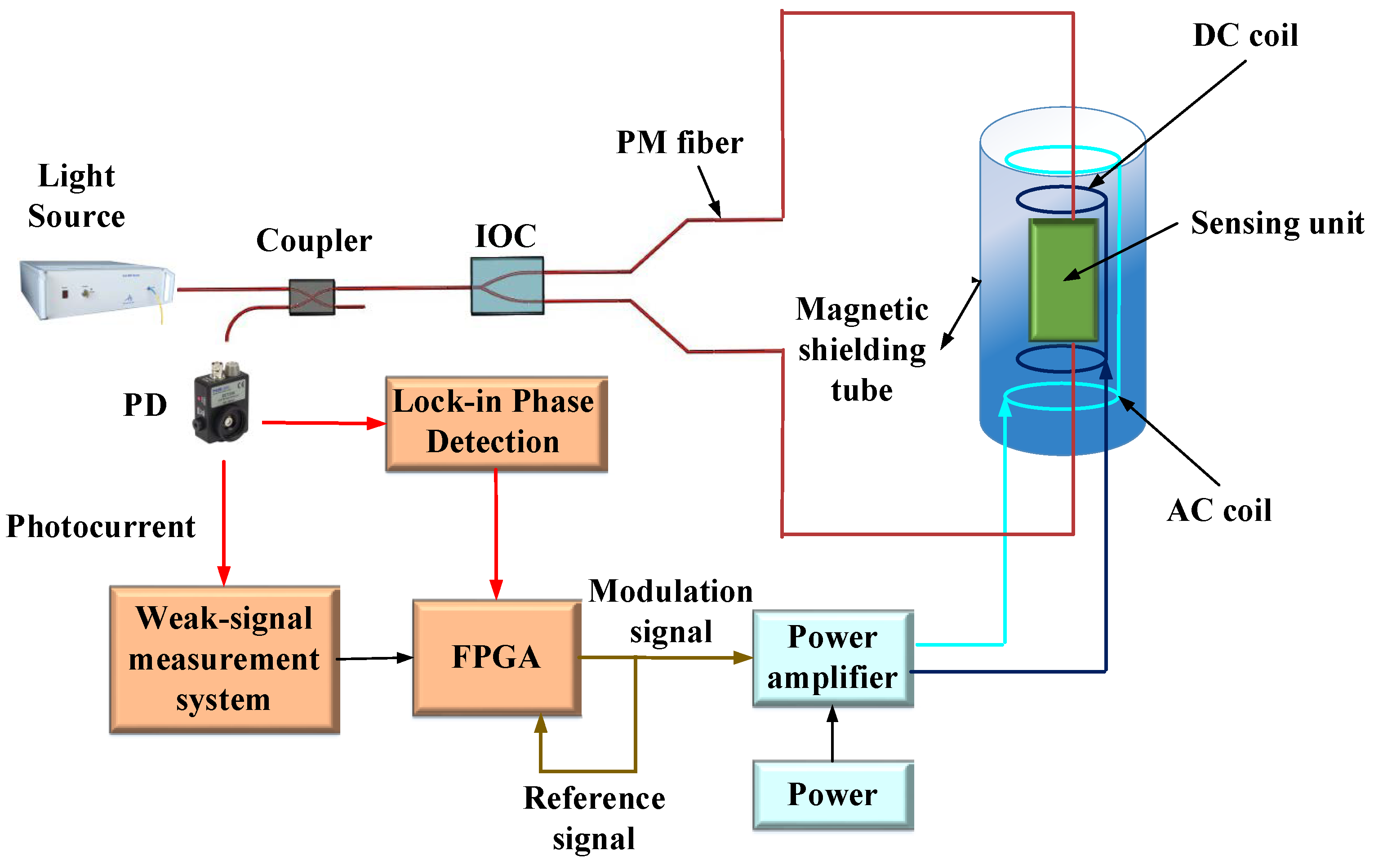
An experimental demonstration is built based on the scheme mentioned above, as shown in
Figure 3. The light source is an amplified spontaneous emission (ASE) broad-band source with a working wavelength of 1550 nm, a spectrum width of 40 nm, and a power of 80 mW. The sensing unit is placed in a magnetic shielding tube to obtain an environmental condition of an extremely low magnetic field. Torque-free coils are also placed in the tube in order to produce a high-precision DC magnetic field. The magneto-optical crystal is a cylindrical Ga: YIG crystal with a coefficient of 8400 rad/m/T, a length of 2.1 mm, and a diameter of 1.8 mm. The magnetic flux concentrators are made of permalloy material. The photodetector (PD) used is InGaAs PIN. The experiments about the performance of the system are carried out, where the optimal modulation frequency and amplitude are chosen to be 100 Hz and 0.75 Gauss respectively. The results are shown in
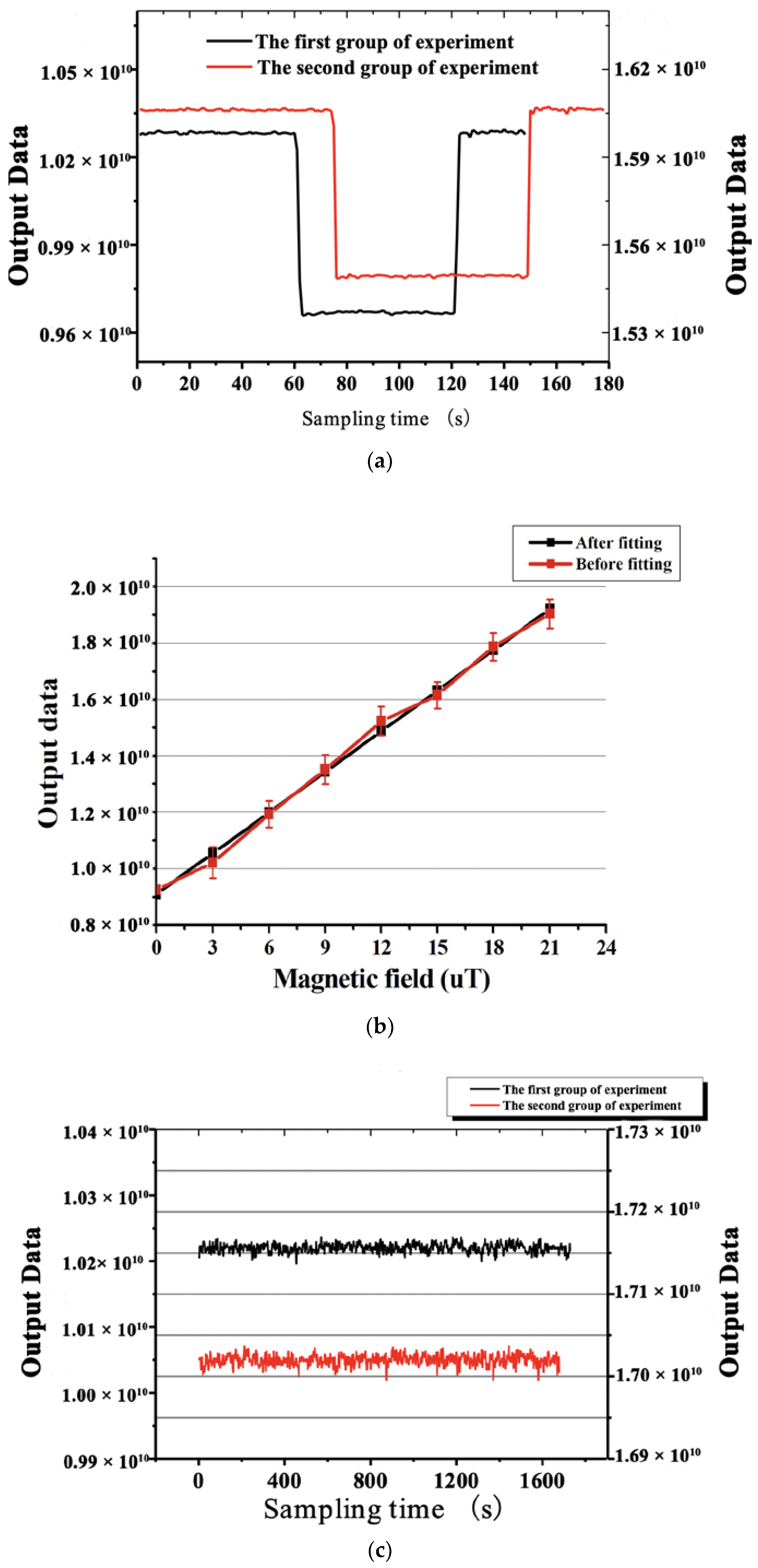
Figure 4.
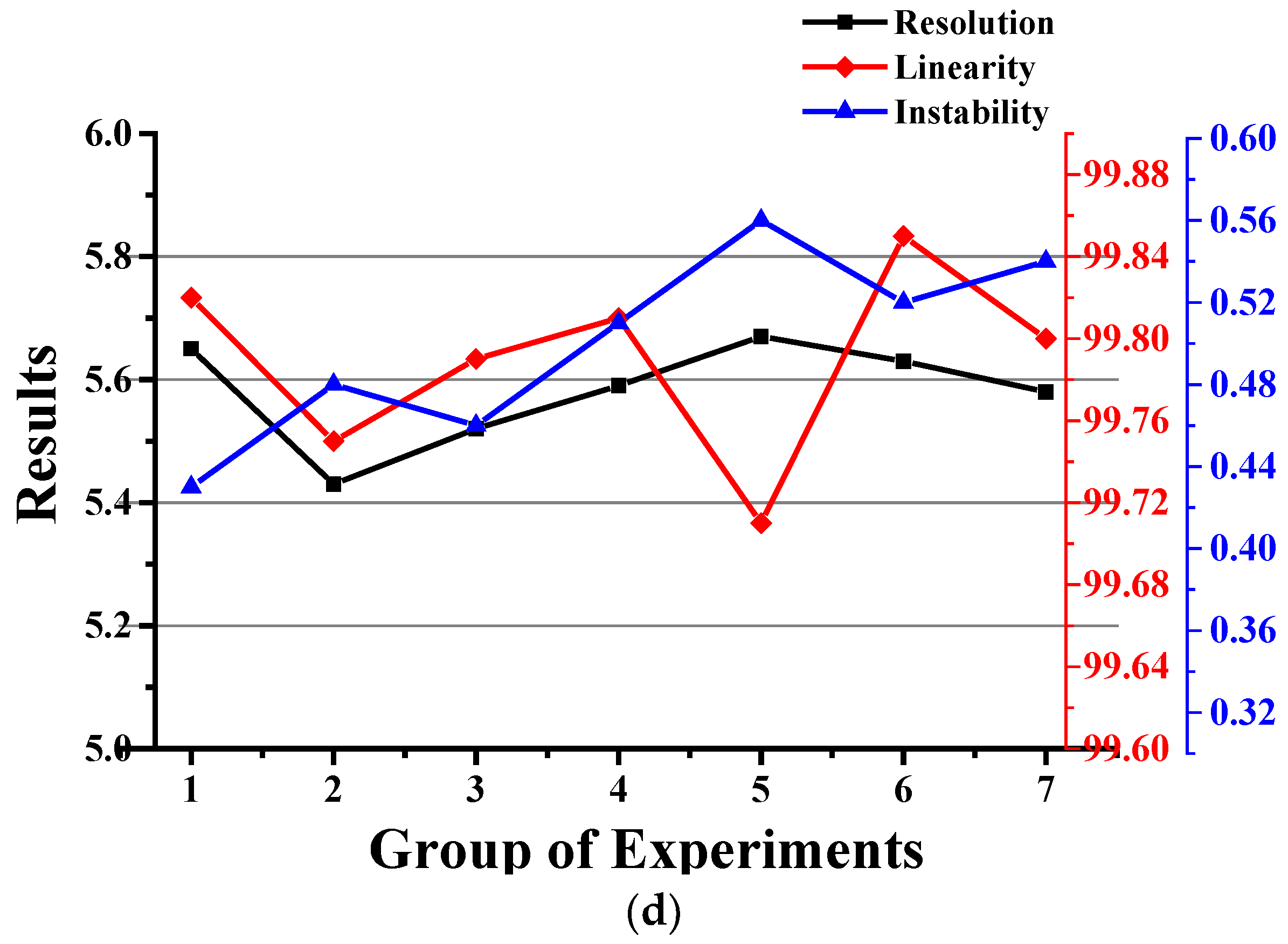
Figure 4a shows the experimental result of the magnetic field resolution of the system. A DC magnetic field with a change of 1 μT is generated by applying a current to the torque-free coils. At the same time, the digital data of the phase lock-in detection output is collected. The experimental results show that the standard deviation of the data corresponds to a magnetic field resolution of 5.6 nT. In order to check the repeatability, the experiment was repeated with another magnetic field strength is carried out, shown as the red line in
Figure 4a. The experimental result shows that the resolution of the system is quite stable.
Figure 4b shows the test result of the linearity of the system. Magnetic fields with different intensities are produced and the collected data is fitted. It can be seen that the output linearity of the system is better than 99.8%.
Figure 4c shows the test result of the instability of the system under different magnetic field strengths, which is less than 0.5% according to the long-term test. The measurement range of the system is not tested due to the limited ability of torque-free coils. Nonetheless, the demonstration has the ability to measure a magnetic field up to 400 G theoretically, which equals the saturation magnetic field strength of the crystal.
There are some factors that decrease the performance of the demonstration, mainly including photoelectric detection errors, optical errors, and environmental errors. In photoelectric detection errors, the indicators of the PD cannot be further improved, which is 0.85 A/W for responsivity and less than 1 nA for dark current. For the purpose of suppressing the detection error to the level of nA, a high-precision weak signal acquisition circuit is specially designed and achieves a dynamic range of around 50 dB. In optical errors, the contribution of photon shot noise to the system decreases with the improvement of optical power. Therefore, the signal-to-noise ratio will be enhanced by raising the light intensity and the coupling efficiency of the optical devices. The effect of the relative intensity noise (RIN) of the light source on measurement errors is proportional to the square of the working wavelength, inversely proportional to the spectral width, and has nothing to do with the optical power. The back reflection and back scattering cannot be ignored either, which will introduce errors to the system due to the interference of undesirable signals. The latter two optical errors can be inhibited by using a wide-band light source. In environmental errors, the temperature is one of the main components. In the previous study, we found that a coupling effect that could cause a serious nonreciprocal phase error would show up in the fiber under time-varying temperatures and magnetic fields [
21]. The model of the effect was established and a corresponding compensation method was proposed.
4. Conclusions
Weak magnetic field sensors with high resolution, high stability, miniaturization, and vectorized measurement have abundant applications. A fiber optic all-polarization Sagnac magnetic field sensor is proposed, which combines the co-path interference characteristic of the Sagnac structure to suppress polarization, phase drifts, and the high magneto-optics coefficient of Ga: YIG to improve the resolution of the measurement. The theoretical model of the system is established. A type of magnetic flux concentrator that can achieve a magnetic field gain of 377 times is designed. The experimental system is demonstrated and the main indicators are tested. The main errors affecting the system performance are analyzed and restrained. The experimental results show that the proposed magnetic field sensor has a high magnetic field resolution of 5.6 nT, a dynamic range of larger than 70 dB, good linearity of 99.8%, and an instability of less than 0.5%. Moreover, the scheme has the potential to continuously improve the resolution and is expected to be applied to underwater target detection and some other fields.


