Polarization-Dependent Absorption and Transmission Metasurfaces for Linearly and Circularly Polarized Light in Terahertz Band

 , ,
, , 
Abstract
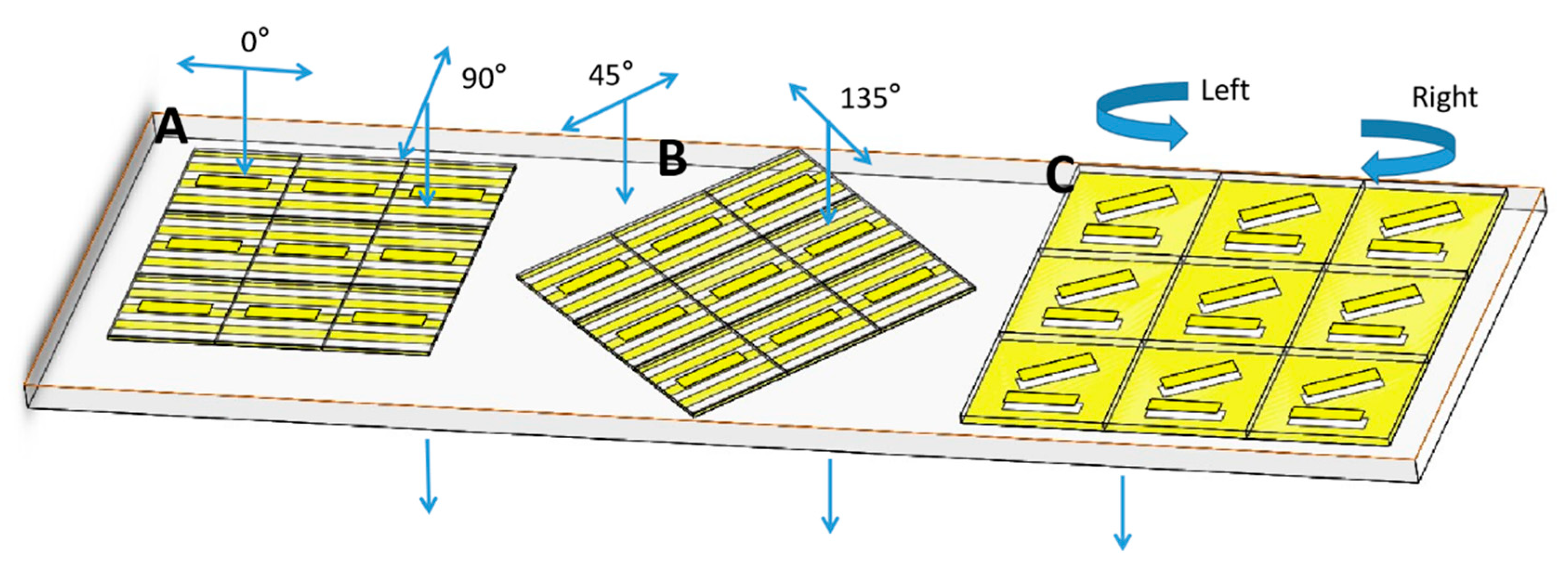
:1. Introduction
2. Results and Discussion
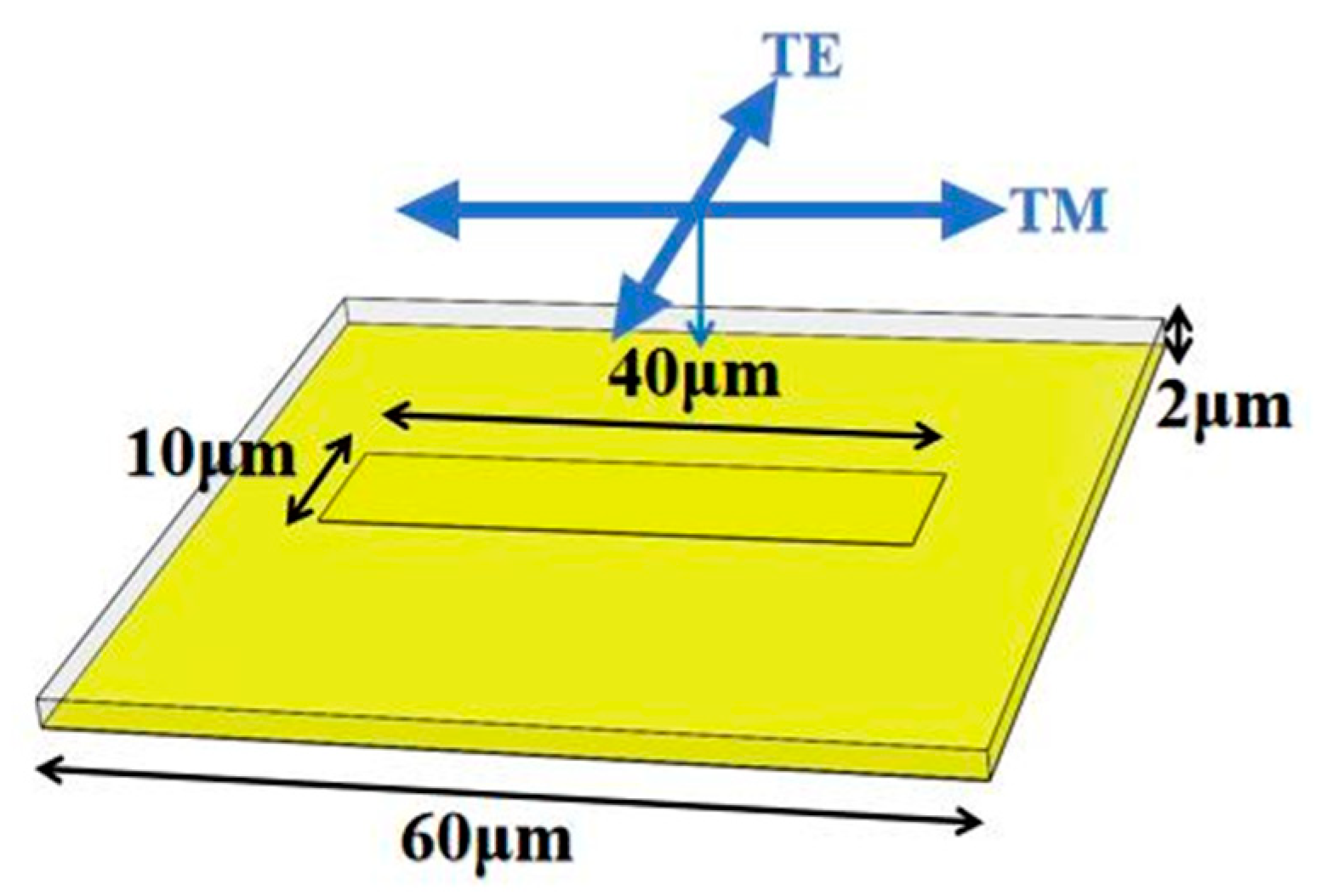
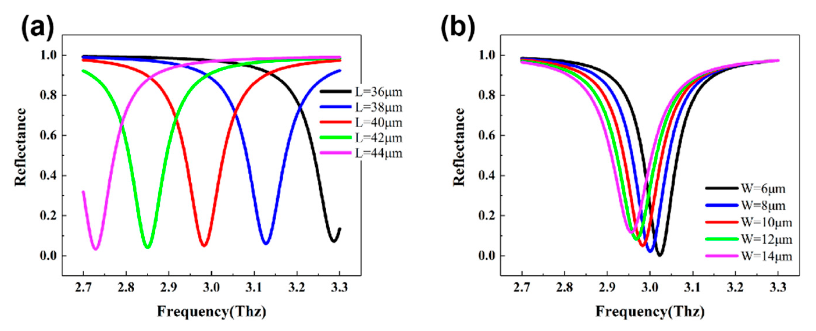
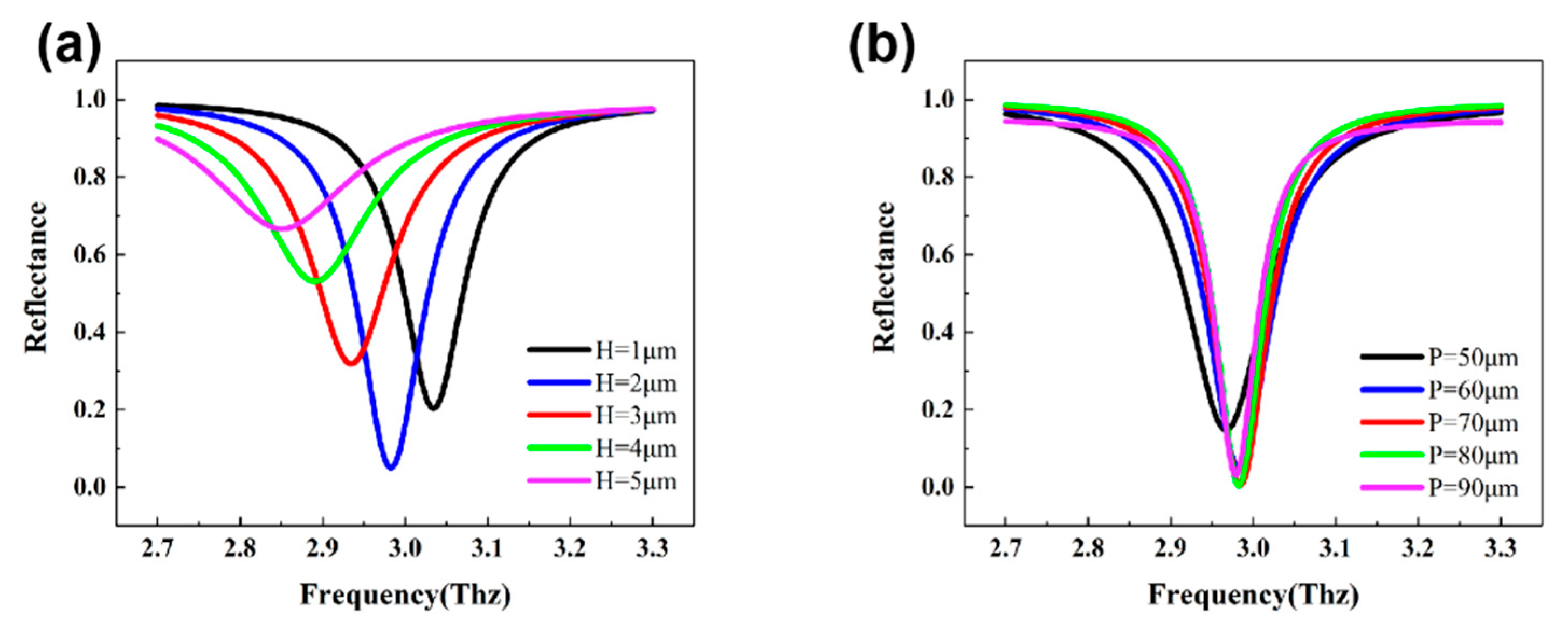
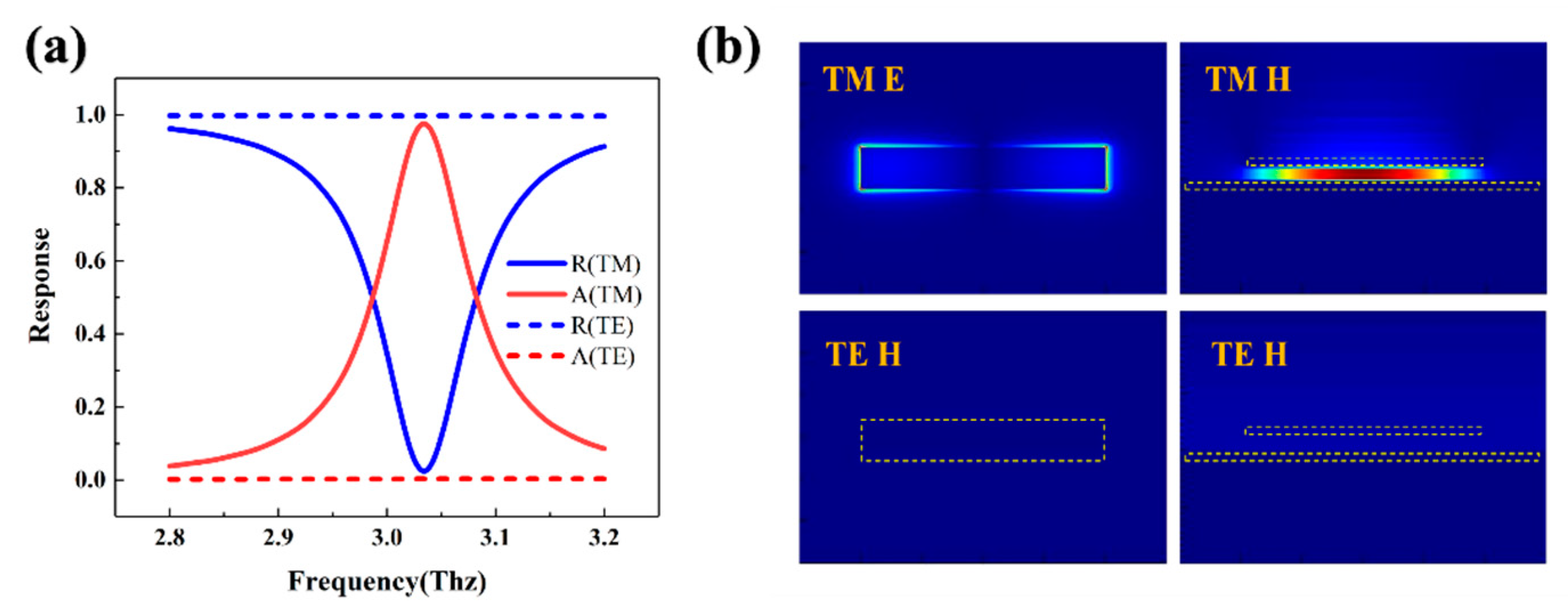
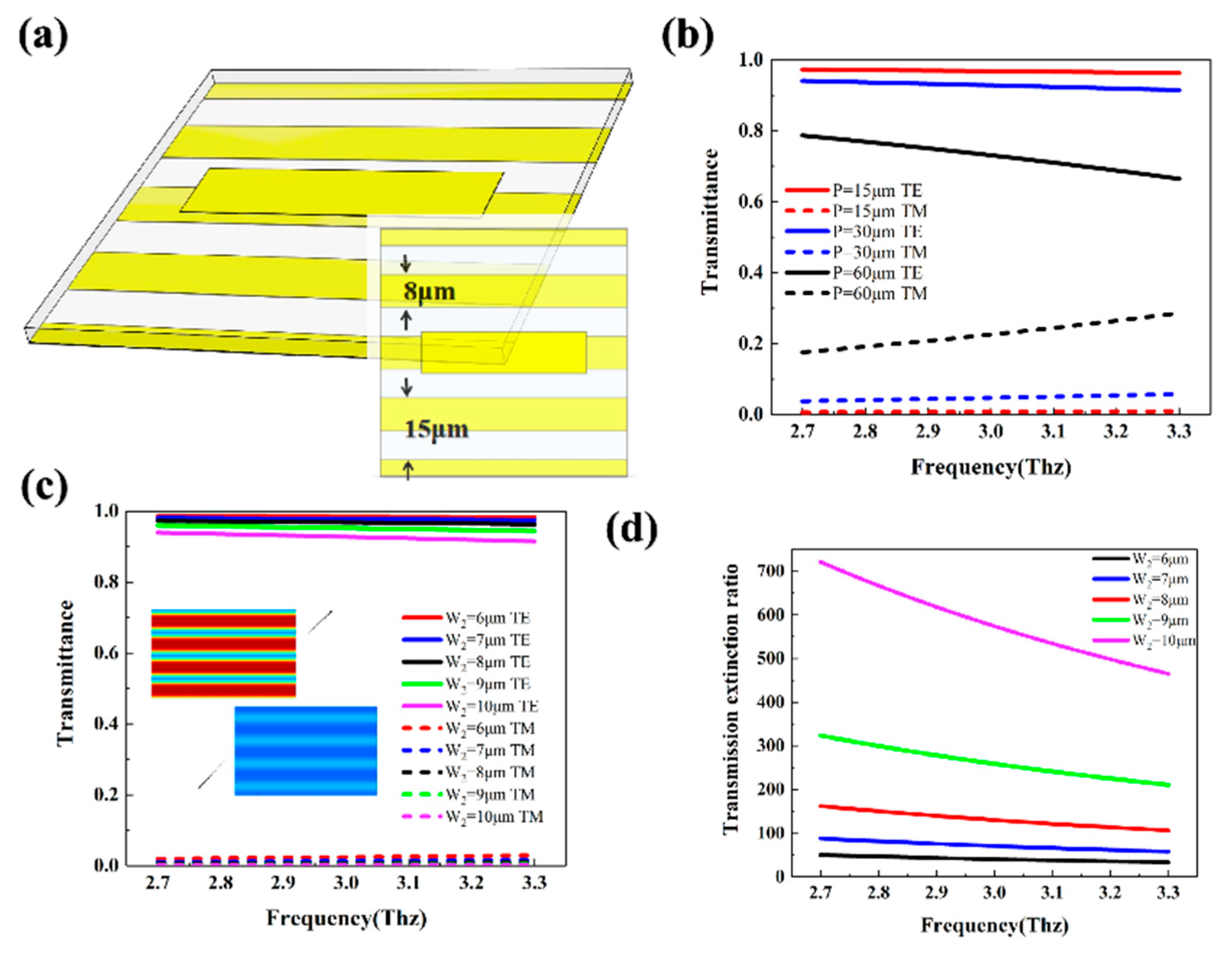
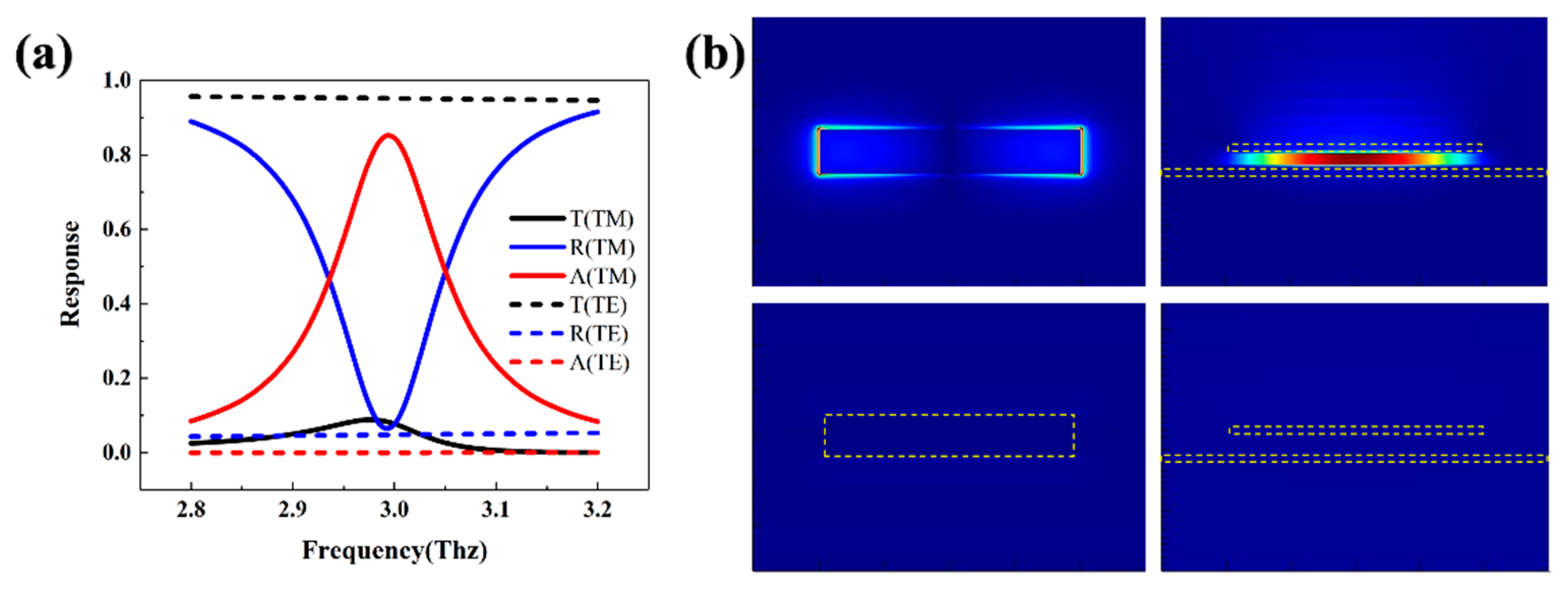
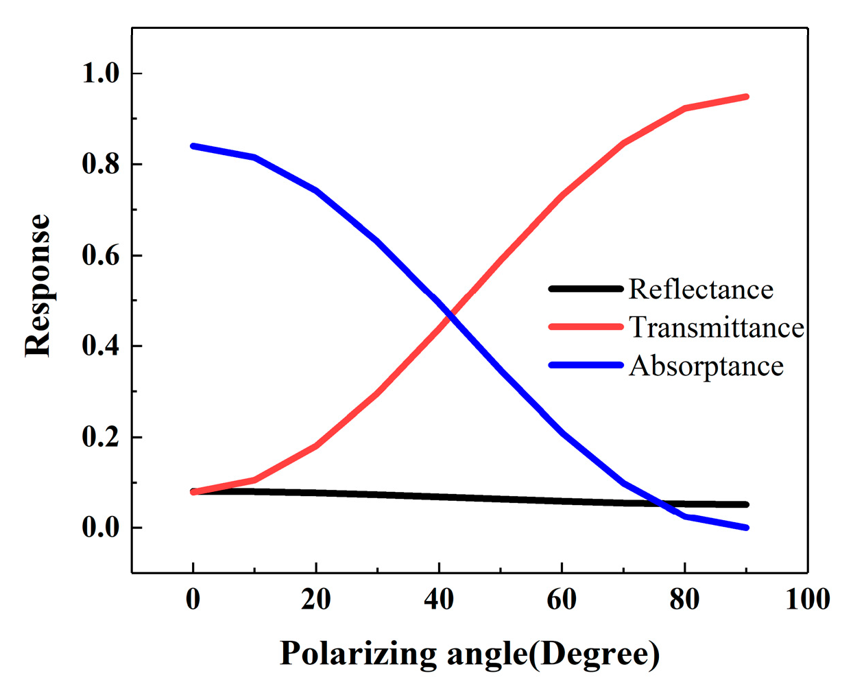
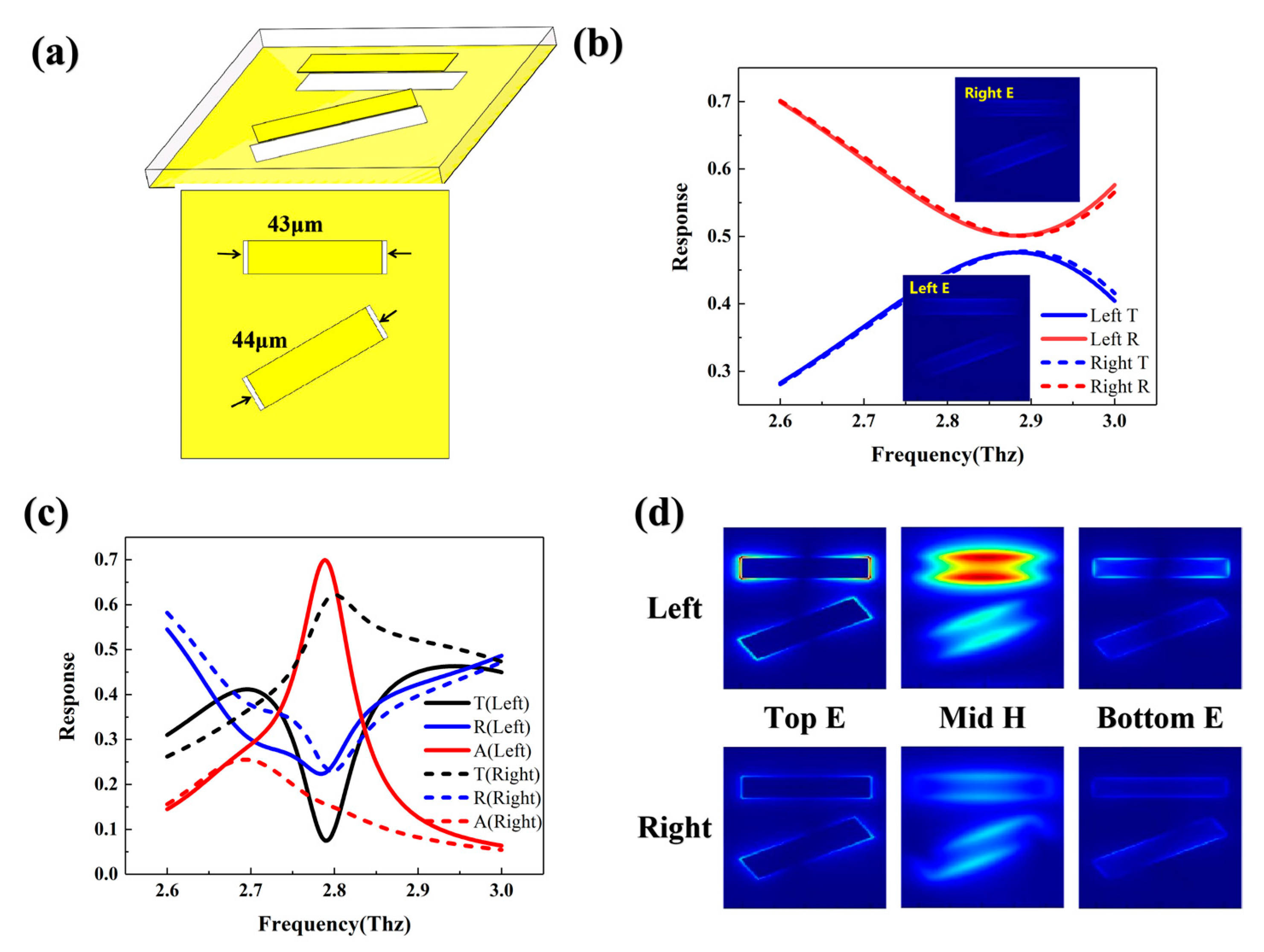
2.1. Polarization Dependent Transmission and Absorption Structure for Linearly Polarized Light
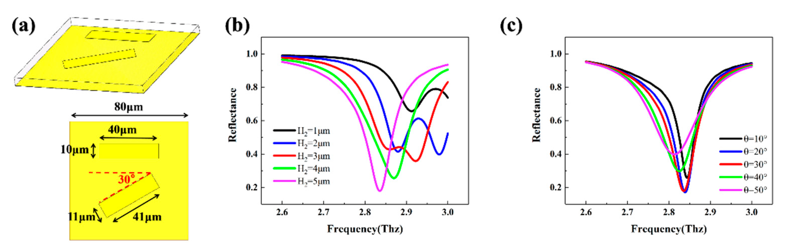
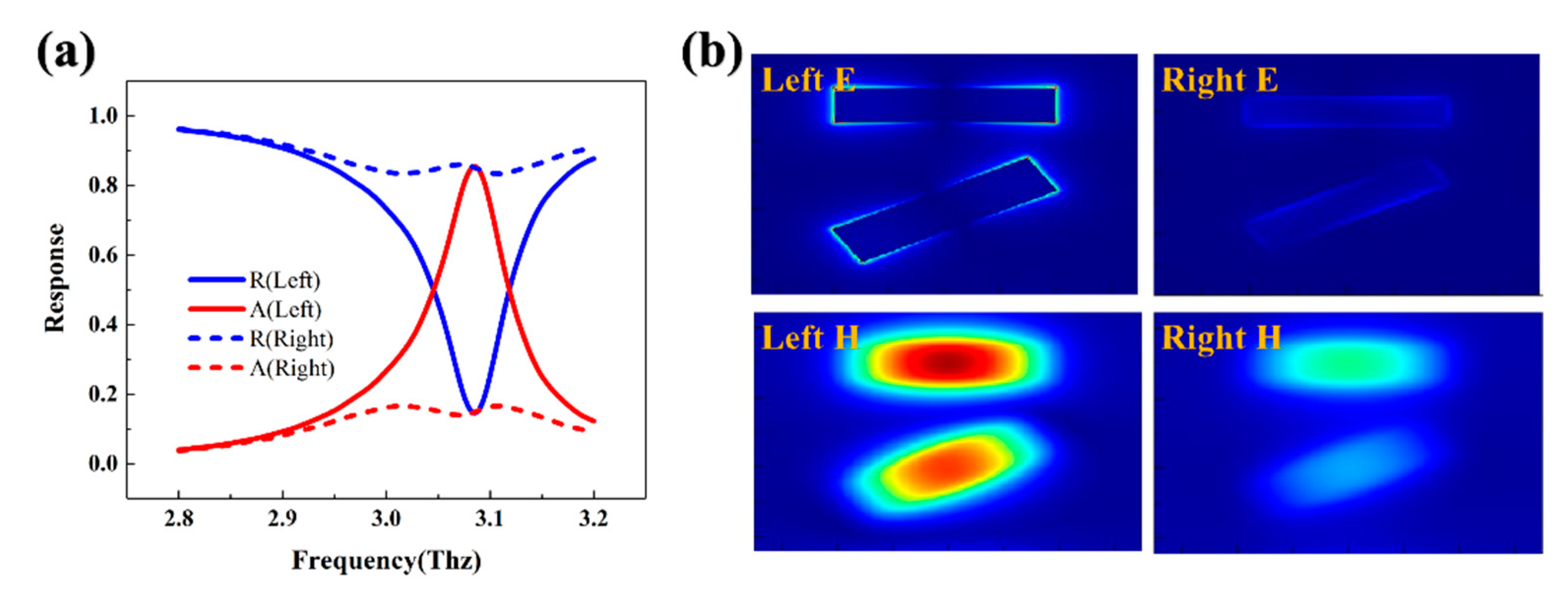
2.2. Polarization-Dependent Transmission and Absorption Structure for Circularly Polarized Light
3. Conclusions
Author Contributions
Funding
Institutional Review Board Statement
Informed Consent Statement
Data Availability Statement
Conflicts of Interest
References
- Zhong, S. Progress in terahertz nondestructive testing: A review. Front. Mech. Eng. 2019, 14, 273–281. [Google Scholar] [CrossRef]
- Amenabar, I.; Lopez, F.; Mendikute, A. In introductory review to THz non-destructive testing of composite mater. J. Infrared Millim. Terahertz Waves 2013, 34, 152–169. [Google Scholar] [CrossRef]
- Goyal, R. Vishwakarma D K. Design of a graphene-based patch antenna on glass substrate for high-speed terahertz communications. Microw. Opt. Technol. Lett. 2018, 60, 1594–1600. [Google Scholar] [CrossRef]
- Jia, S.; Wang, S.; Liu, K.; Pang, X.; Zhang, H.; Jin, X.; Zheng, S.; Chi, H.; Zhang, X.; Yu, X. A unified system with integrated generation of high-speed communication and high-resolution sensing signals based on THz photonics. J. Light. Technol. 2018, 36, 4549–4556. [Google Scholar] [CrossRef]
- Withington, S. Terahertz astronomical telescopes and instrumentation. Philosophical Transactions of the Royal Society of London. Ser. A Math. Phys. Eng. Sci. 2004, 362, 395–402. [Google Scholar]
- Kulesa, C. Terahertz spectroscopy for astronomy: From comets to cosmology. IEEE Trans. Terahertz Sci. Technol. 2011, 1, 232–240. [Google Scholar] [CrossRef]
- Shangguan, Q.; Chen, Z.; Yang, H.; Cheng, S.; Yang, W.; Yi, Z.; Wu, X.; Wang, S.; Yi, Y.; Wu, P. Design of ultra-narrow band graphene refractive index sensor. Sensors 2022, 22, 6483. [Google Scholar] [CrossRef]
- Wang, X.; Lin, J.; Yan, Z.; Yi, Z.; Yu, J.; Zhang, W.; Qin, F.; Wu, X.; Zhang, J.; Wu, P. Tunable high-sensitivity sensing detector based on Bulk Dirac semimetal. RSC Adv. 2022, 12, 32583–32591. [Google Scholar] [CrossRef]
- Escorcia, I.; Grant, J.; Gough, J.; Cumming, D.R.S. Uncooled CMOS terahertz imager using a metamaterial absorber and pn diode. Opt. Lett. 2016, 41, 3261–3264. [Google Scholar] [CrossRef] [Green Version]
- Carranza, I.E.; Grant, J.P.; Gough, J.; Cumming, D. Terahertz metamaterial absorbers implemented in CMOS technology for imaging applications: Scaling to large format focal plane arrays. IEEE J. Sel. Top. Quantum Electron. 2016, 23, 2630307. [Google Scholar]
- Jornet, J.M.; Akyildiz, I.F. Graphene-based plasmonic nano-antenna for terahertz band communication in nanonetworks. IEEE J. Sel. Areas Commun. 2013, 31, 685–694. [Google Scholar] [CrossRef]
- Pan, W.; Shen, T.; Ma, Y.; Zhang, Z.; Yang, H.; Wang, X.; Zhang, X.; Li, Y.; Yang, L. Dual-band and polarization-independent metamaterial terahertz narrowband absorber. Appl. Opt. 2021, 60, 2235–2241. [Google Scholar] [CrossRef]
- Zheng, Z.; Zheng, Y.; Luo, Y.; Yi, Z.; Zhang, J.; Liu, Z.; Yang, W.; Yu, Y.; Wu, X.; Wu, P. A switchable terahertz device combining ultra-wideband absorption and ultra-wideband complete reflection. Phys. Chem. Chem. Phys. 2022, 24, 2527–2533. [Google Scholar] [CrossRef] [PubMed]
- Ning, R.; Bao, J.; Jiao, Z.; Xu, Y. Omnidirectional polarization-insensitive tunable absorption in graphene metamaterial of nanodisk structure. J. Appl. Phys. 2015, 118, 203101. [Google Scholar] [CrossRef]
- Chen, H.; Chen, Z.; Yang, H.; Wen, L.; Yi, Z.; Zhou, Z.; Dai, B.; Zhang, J.; Wu, X.; Wu, P. Multi-mode surface plasmon resonance absorber based on dart-type single-layer graphene. RSC Adv. 2022, 12, 7821–7829. [Google Scholar] [CrossRef] [PubMed]
- Hokmabadi, M.P.; Wilbert, D.S.; Kung, P.; Kim, S.M. Polarization-dependent, frequency-selective THz stereometamaterial perfect absorber. Phys. Rev. Appl. 2014, 1, 044003. [Google Scholar] [CrossRef]
- Hu, F.; Zou, T.; Quan, B.; Xu, X.; Bo, S.; Chen, T.; Wang, L.; Gu, C.; Li, J. Polarization-dependent terahertz metamaterial absorber with high absorption in two orthogonal directions. Opt. Commun. 2014, 332, 321–326. [Google Scholar] [CrossRef]
- Yu, H.; Meng, D.; Liang, Z.; Xu, H.; Qin, Z.; Su, X.; Smith, D.R.; Liu, Y. Polarization-dependent broadband absorber based on composite metamaterials in the long-wavelength infrared range. Opt. Express 2021, 29, 36111–36120. [Google Scholar] [CrossRef]
- Ouyang, L.; Wang, W.; Rosenmann, D.; Czaplewski, D.A.; Gao, J.; Yang, X. Near-infrared chiral plasmonic metasurface absorbers. Opt. Express 2018, 26, 31484–31489. [Google Scholar] [CrossRef] [Green Version]
- Mahmud, M.S.; Rosenmann, D.; Czaplewski, D.A.; Gao, J.; Yang, X. Chiral plasmonic metasurface absorbers in the mid-infrared wavelength range. Opt. Lett. 2020, 45, 5372–5375. [Google Scholar] [CrossRef]
- Tang, H.; Rosenmann, D.; Czaplewski, D.A.; Yang, X.; Gao, J. Dual-band selective circular dichroism in mid-infrared chiral metasurfaces. Opt. Express 2022, 30, 20063–20075. [Google Scholar] [CrossRef] [PubMed]
- Tang, B.; Li, Z.; Palacios, E.; Liu, Z.; Butun, S.; Aydin, K. Chiral-selective plasmonic metasurface absorbers operating at visible frequencies. IEEE Photonics Technol. Lett. 2017, 29, 295–298. [Google Scholar] [CrossRef]
- Wu, P.C.; Chen, J.W.; Yin, C.W.; Lai, Y.C.; Chung, T.L.; Liao, C.Y.; Chen, B.H.; Lee, K.-W.; Chuang, C.-J.; Wang, C.-M.; et al. Visible metasurfaces for on-chip polarimetry. ACS Photonics 2017, 5, 2568–2573. [Google Scholar] [CrossRef]
- Arbabi, E.; Kamali, S.M.; Arbabi, A.; Faraon, A. Full-Stokes imaging polarimetry using dielectric metasurfaces. ACS Photonics 2018, 5, 3132–3140. [Google Scholar] [CrossRef] [Green Version]
- Brand, G.F. The strip grating as a circular polarizer. Am. J. Phys. 2003, 71, 452–456. [Google Scholar] [CrossRef]
- Basiri, A.; Chen, X.; Bai, J.; Amrollahi, P.; Carpenter, J.; Holman, Z.; Wang, C.; Yao, Y. Nature-inspired chiral metasurfaces for circular polarization detection and full-Stokes polarimetric measurements. Light Sci. Appl. 2019, 8, 78. [Google Scholar] [CrossRef]


Disclaimer/Publisher’s Note: The statements, opinions and data contained in all publications are solely those of the individual author(s) and contributor(s) and not of MDPI and/or the editor(s). MDPI and/or the editor(s) disclaim responsibility for any injury to people or property resulting from any ideas, methods, instructions or products referred to in the content. |
© 2023 by the authors. Licensee MDPI, Basel, Switzerland. This article is an open access article distributed under the terms and conditions of the Creative Commons Attribution (CC BY) license (https://creativecommons.org/licenses/by/4.0/).
Share and Cite
Yang, B.; Ouyang, M.; Ren, H.; Wu, J.; Zhang, Y.; Fu, Y. Polarization-Dependent Absorption and Transmission Metasurfaces for Linearly and Circularly Polarized Light in Terahertz Band. Photonics 2023, 10, 100. https://doi.org/10.3390/photonics10020100
Yang B, Ouyang M, Ren H, Wu J, Zhang Y, Fu Y. Polarization-Dependent Absorption and Transmission Metasurfaces for Linearly and Circularly Polarized Light in Terahertz Band. Photonics. 2023; 10(2):100. https://doi.org/10.3390/photonics10020100
Chicago/Turabian StyleYang, Bowei, Mingzhao Ouyang, Hang Ren, Jinshuang Wu, Yixin Zhang, and Yuegang Fu. 2023. "Polarization-Dependent Absorption and Transmission Metasurfaces for Linearly and Circularly Polarized Light in Terahertz Band" Photonics 10, no. 2: 100. https://doi.org/10.3390/photonics10020100