Article

Exploration of Large-Scale Application of Efficient and Clean Utilization of Low-Grade Bauxite

1
School of Materials Science and Engineering, Guilin University of Technology, Guilin 541004, China
2
School of Metallurgy, Northeastern University, Shenyang 110819, China
*
Author to whom correspondence should be addressed.
Separations 2023, 10(6), 336; https://doi.org/10.3390/separations10060336
Submission received: 13 April 2023 / Revised: 26 May 2023 / Accepted: 26 May 2023 / Published: 30 May 2023
(This article belongs to the Special Issue Efficient and Green Recovery of Metal Minerals)

Abstract

:
In recent years, the rapid development of the domestic alumina industry has greatly accelerated the consumption of high-alumina–silica-ratio bauxite resources in China. The development of an efficient and clean utilization technology applicable to low-grade bauxite in China is not only a requirement for resource and environmental protection, but also a powerful guarantee to maintain the sustainable development of China’s aluminum industry. Based on this, the authors’ team proposed a new process for the treatment of low-grade bauxite ore via a calcification–carbonization method from the perspective of equilibrium solid-phase reconstruction and achieved the first industrial-scale trial run on the basis of existing laboratory research. The results show that the mass fraction of Na2O in bauxite residue can be reduced to 0.95% in the treatment of typical diaspore bauxite, the A/S in the bauxite residue can be reduced to 0.85 after two-time carbonization–alumina dissolution, and the actual alumina dissolution rate can reach 81.32%. The relevant results verified the feasibility and advantages of the calcification–carbonization method in industrial production.

1. Introduction

China is the world’s largest alumina producer, with domestic alumina production capacity reaching 96.95 million tons/year by the end of December 2022. On the other hand, in stark contrast to the rapid development of China’s alumina industry, China is not a large-aluminum-resource country and has been facing the problem of balancing higher mining and smaller domestic resource reserves, with greater pressure on resource supply. According to the “Mineral Commodity Summaries 2022”, as of the end of 2019, China’s identified bauxite resource reserves were 5.45 billion tons, including 1 billion tons of base reserves, accounting for only 3% of global bauxite reserves [1]. As China has a huge alumina production capacity as well as an expanding alumina production capacity using imported ores, the dependence on foreign bauxite in China has exceeded 55% at this stage [2,3]. In the future, China’s bauxite imports will continue to keep rising, and the import ratio is expected to reach 80% by 2030. China’s bauxite import demand is mainly for higher-quality overseas gibbsite bauxite, which accounts for 75% of global bauxite imports [4]. Therefore, the development of efficient and clean utilization technologies applicable to low-grade bauxite ores in China is not only a requirement for resource and environmental protection but also a strong guarantee to maintain the sustainable development of China’s aluminum industry.
The utilization technology of low-grade bauxite ore includes two kinds of high-temperature treatment and wet treatment. Among them, the representative technology of high-temperature treatment is the sintering method, which converts silicon in minerals into 2CaO-SiO2 through adding additives such as sodium salts and calcium carbonate to medium- and low-grade bauxite, and this achieves efficient separation of aluminum and silicon through dissolution and other processes [5].
Compared with the high-temperature treatment process, wet utilization technology has become a research hotspot in related fields because of its technical advantages such as low energy consumption, high efficiency of comprehensive utilization of valuable components, and environmental friendliness. The representative technologies under research include the sub-molten salt method, calcium ferrate addition method, and acid leaching method. Among them, the sub-molten salt method is to convert the silicon in bauxite [6] or high-alumina fly ash [7] into calcium sodium silicate (NaCaHSiO4) through adding lime in an alkaline solution system with a high molecular ratio to achieve aluminum–silicon separation, and the calcium sodium silicate is subsequently treated to obtain low-sodium tailings [8,9,10,11]. The calcium ferrate addition method [12,13,14,15] is to convert the silicon in minerals through adding 2CaO⋅Fe2O3 to the Bayer method system. Additives to the Bayer system convert the silicon in the bauxite minerals to iron hydrated garnet (3CaO·0.13Al2O3·0.87Fe2O3·1.65SiO2·2.7H2O), thus achieving the purpose of reducing the tailings’ Al–Si ratio and increasing the alumina recovery. The acid leaching method uses sulfuric or hydrochloric acid to leach the alumina from bauxite [16] or high-alumina fly ash [17], where the silicon in the raw material is mainly in the form of SiO2 in the form of tailings. The main objective of both pyro- and hydrometallurgical processes is to change the way aluminum and silicon are combined in the tailings during alumina production to obtain one or more equilibrium solid phases with low aluminum-to-silicon ratio (or without aluminum) [18]. At present, a lot of research has also been conducted by relevant domestic research institutes and enterprises around the process of physical phase transformation of the above treatment technologies [19,20,21]. However, the relevant studies are in the laboratory stage, and further industrial applications are needed.
The authors’ team proposed a new method of “calcification-carbonization” to treat low-grade bauxite [22,23,24]. Firstly, all the silicon in the bauxite is converted into a calcium–aluminum–silica compound (hydrated garnet) through adding lime during the dissolution process, which completes the calcification dissolution transformation. The carbonization process of the calcified transformation slag (mainly composed of hydrated garnet) is carried out using CO2 to obtain a carbonized slag with the main components of calcium silicate, calcium carbonate, and aluminum hydroxide, i.e., carbonized transformation; the carbonized slag can then be dissolved at a low temperature to obtain a new structural red mud with the main components of calcium silicate and calcium carbonate, which can be used as a raw material for the cement industry or for soil treatment. Using this method, a large number of laboratory studies have been conducted on different regions and types of bauxite ores, and all of them have achieved good experimental results. Therefore, in this paper, on the basis of laboratory studies, a semi-industrial experiment of 120,000 tons/year was conducted to further study the variation law of reaction conditions of each link in an industrial scale plant, to determine the industrial production equipment for the core processes of calcification and carbonization, and to provide experimental basis and reference for the further industrial application of the process.

2. Materials and Methods

This semi-industrial experiment is based on the original Bayer process dissolution system of the plant to adjust the ingredients for calcination dissolution and send the slurry to the carbonization–alumina dissolution process after reaching the predetermined effect of calcination transformation, which will not change the original Bayer process of the alumina plant. The flow diagram of the industrial experiment is shown in Figure 1. Bauxite and lime enter the mill through the dosing machine according to a certain ratio and enter the dissolution system after fully mixing with the circulating mother liquor. The calcified slurry is stored in the calcified slurry tank for backup after the casing dissolution when the calcified slurry composition reaches the expected target. Before carbonization, the calcified slurry is sent to the intermediate tank through the pipe for settling and washing, and after washing, the solid content is adjusted according to the carbonization experimental conditions, and then pumped to the carbonization tank and heated with steam, and after reaching the reaction temperature, CO2 gas is introduced for the carbonization decomposition experiment. After the carbonization reaction, the carbonized slurry is sent to the aluminum dissolution tank for settling and separation. Then, the solid content is adjusted according to the aluminum dissolution experimental conditions, and liquid alkali is added for reaction when the temperature rises to the predetermined temperature. Finally, the alumina dissolution slurry is separated and washed. The filter residue is returned to the aforementioned carbonization and alumina dissolution process for multiple carbonization and alumina dissolution to improve the extraction rate of alumina.
The bauxite used in the experiments is a typical diaspore bauxite from the Shanxi and Henan regions. The chemical composition of the bauxite residue obtained via X-ray fluorescence (XRF) (type: ZSX100e, Rigaku, Tokyo, Japan) is listed in Table 1. The minerals used are Al2O3 with 61.6% mass fraction, SiO2 with 13.53% mass fraction, and an aluminum-to-silicon ratio (A/S) of 4.55, which is a typical for low-grade diaspore bauxite in China.
The phase composition of the bauxite and dissolved solid phase were analyzed using D8 X-ray diffraction (XRD, type: Bruker D8 Advance, Saarbrucken, Germany) with Cu Kα-ray source over the range of 5–90°. XRD analysis was performed on the raw ore, and the results (Figure 2) show that the main phases in this bauxite are diaspore and kaolinite. The circulating mother liquor used in the experimental process was from the alumina plant production system, and the circulating mother liquor Nk = 265–270 g/L, αk = 4. The effective composition of lime used in the calcination process was 85.8%. The CO2 used in the carbonization process was in industrial bottles with a purity of >99%. The lye used in the aluminum dissolution process was industrial liquid soda ash (sodium hydroxide) with a mass concentration of 30% to 32%.
The solid phase morphology was obtained using SEM (SU9000, Hitachi, Tokyo, Japan). Figure 3 shows the morphological analysis of the bauxite. The bauxite particles used in the experiments are fine, with a particle size of about 10 μm, and are mainly massive and flaky particles.
The experiments were carried out using the original Bayer process production system of this alumina plant for calcium transformation dissolution, the carbonization experiments were carried out in a modified flash tank and condensate tank, and the aluminum dissolution process was carried out in a homemade aluminum dissolution tank (intermediate tank). The main equipment and specifications are shown in Table 2.

3. Results and Discussion

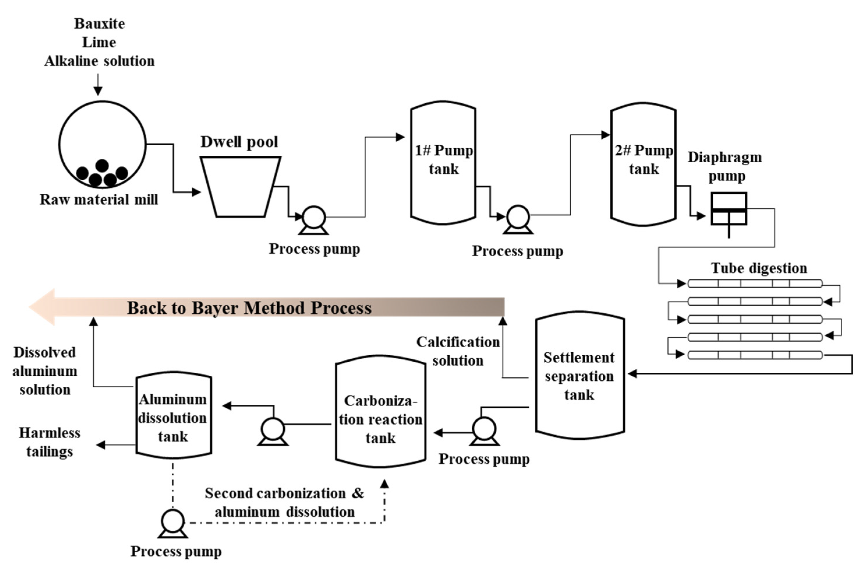
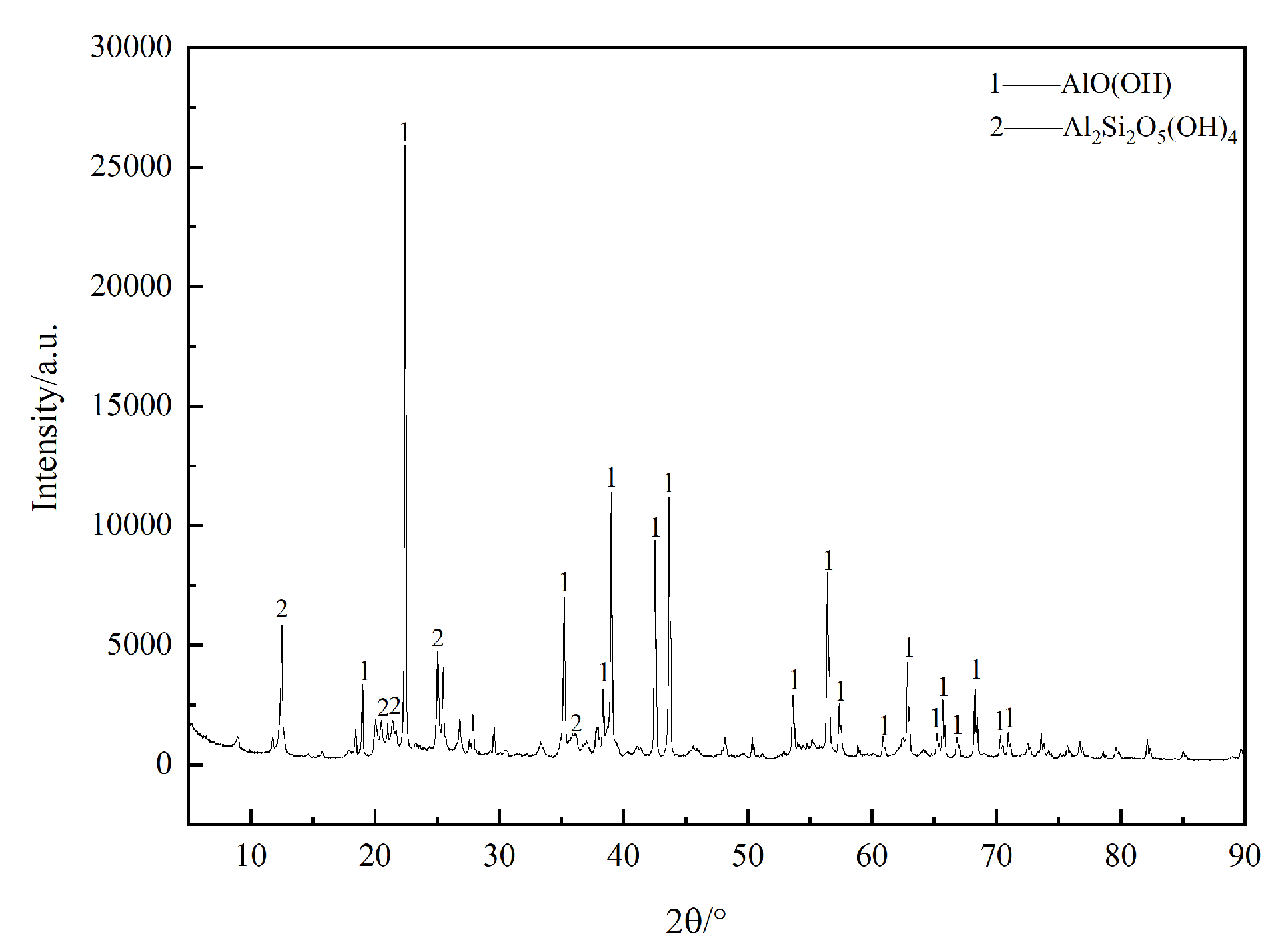
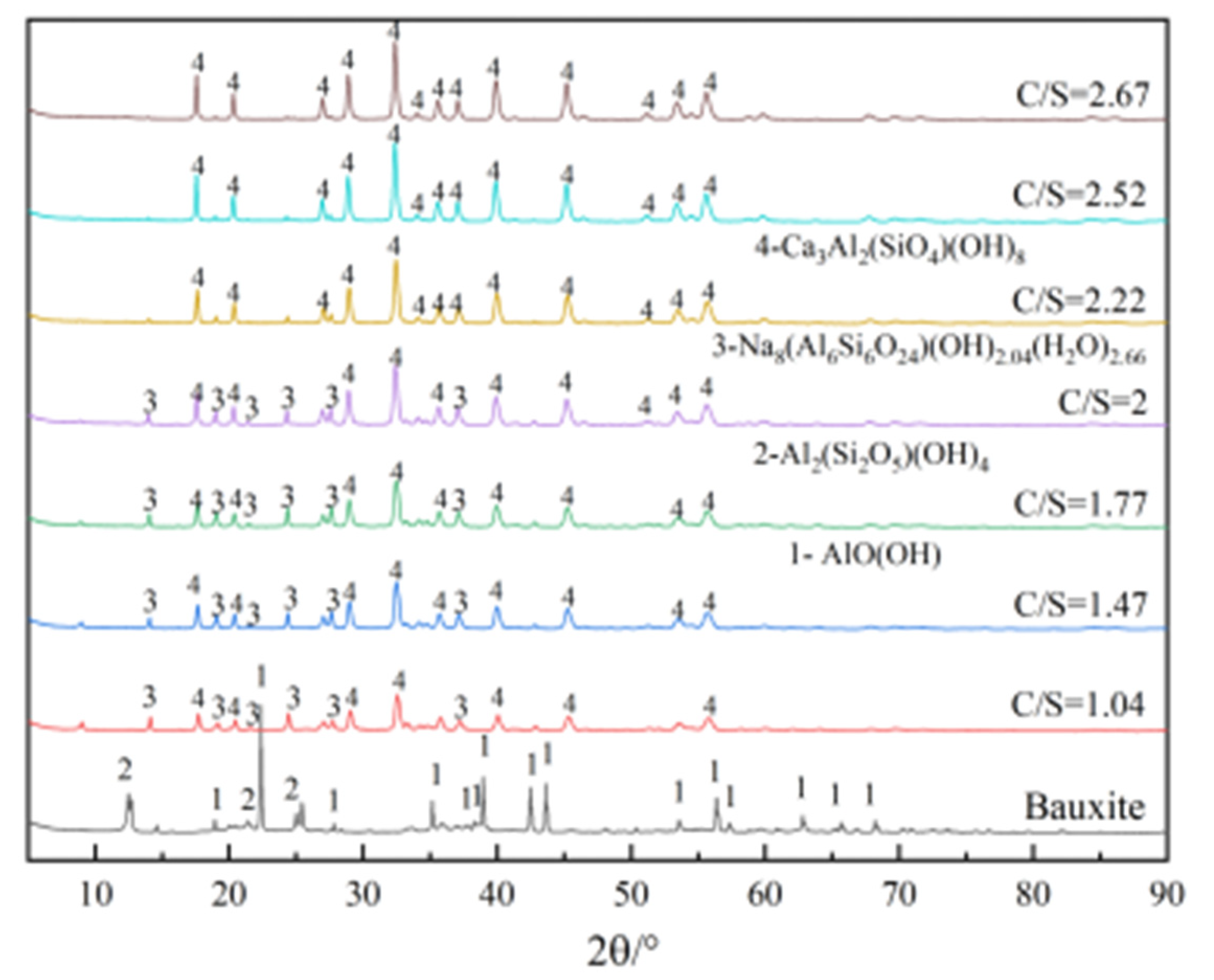
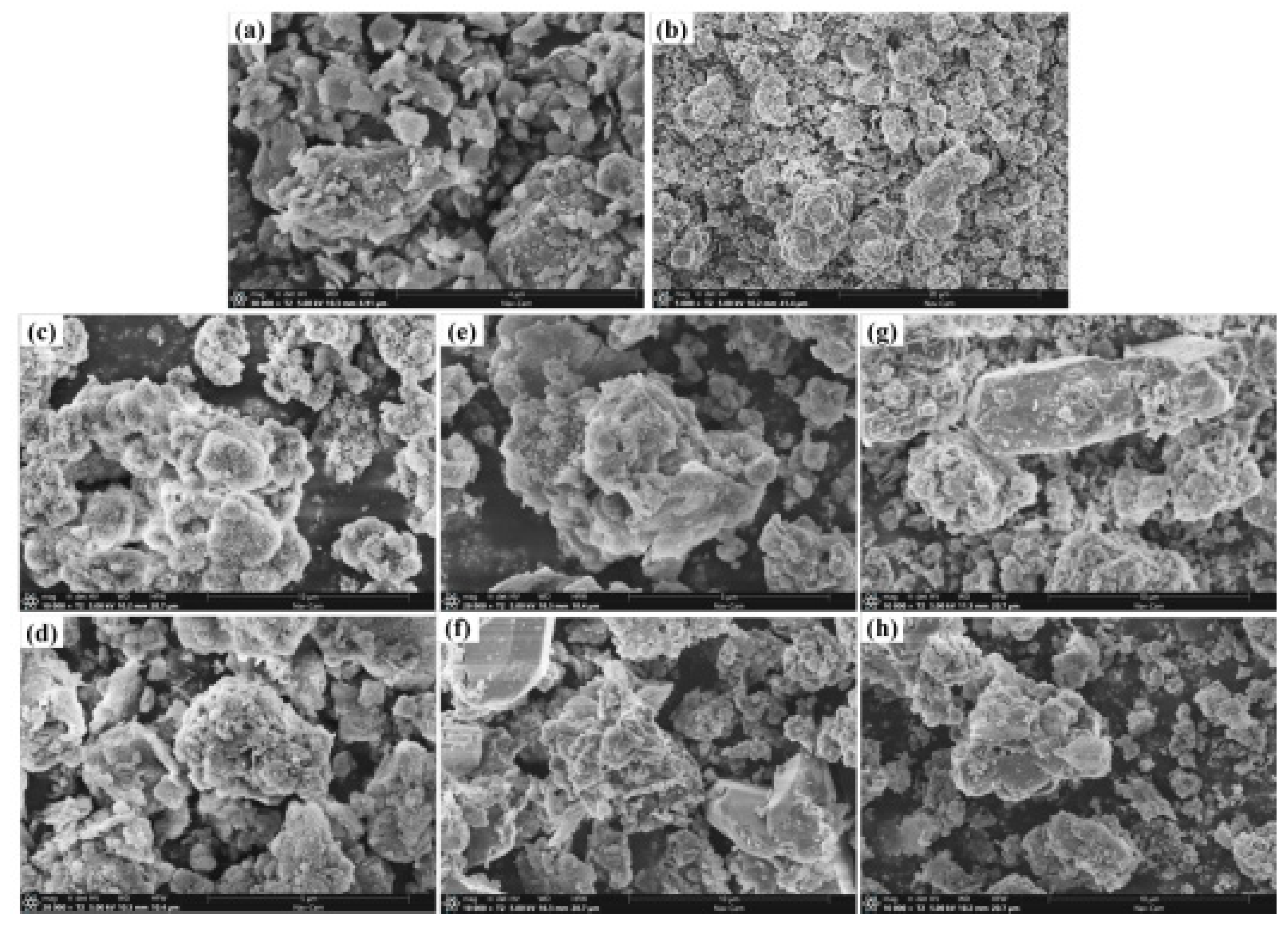
3.1. Calcification Process

According to the results of small laboratory experiments and extended test experiments, the experimental conditions of bauxite calcification dissolution process are as follows: temperature, 265 °C; calcium–silica ratio, 2.75:1; liquid–solid ratio, 5:1; alkali concentration of sodium aluminate solution, 265~270 g/L. The ore and lime were transferred into the mill via belt according to the ratio, the flow rate under each mill was 17.5 t/h, the lime was given 7 t/h, and the effective composition of lime was 85.8%. The proportioning of alkali was 40 m³/t-ore, the raw material was moved into the mill 4 h after the slurry into the pump, and the total grinding slurry was 1780 m3. The solid content of the pulp was 360~370 g/L, the volume of the incoming pulp was 120 m3 /h, and the temperature was kept at 270~275 °C. After the start of the experiment, some of the dissolved slurry was filtered and washed every 1 h, and the changes of the content of each component in the solid phase were analyzed; the relevant results are shown in Figure 4.
From Figure 4, the composition trend of the dissolved solid phase can be seen. With the increase of the calcium–silicon ratio, the content of sodium oxide in the calcified dissolved slag decreases significantly, and the equilibrium solid phase of the dissolved slag is changed from sodium aluminosilicate hydrate to hydrated garnet. There was a small increase in the dissolved A/S and a large decrease in the sodium-to-silicon ratio; when the calcium to silicon ratio was 2.49:1, the A/S was 1.34, the sodium-to-silicon ratio was 0.08, and the mass fraction of sodium oxide in the calcified slag was 1.21%. Under the same conditions, the laboratory pilot experiment at a calcium–silica ratio of 2.5:1, the A/S was 1.34, the sodium–silica ratio was 0.09, and the mass fraction of sodium oxide in the calcified slag was 1.45%, which shows that the calcium dissolution effect of the industrial experiment was better. Compared with the laboratory experiment, the grinding action of the mill in the industrial experiment makes the ore particle size finer, which allows the subsequent dissolution reaction to proceed more fully.
As can be seen from Figure 5, with the increase in the ratio of calcined lime, the AO (alumina) content in the liquid phase of the raw slurry decreases significantly, with a drop of more than 10 g/L, and αk increases significantly. In the liquid phase of the dissolved slurry, due to the high molecular ratio of the ingredients, the dissolved αk rises more obviously, and the dissolved solid content rises about 30 g/L. The carbon base content of the liquid phase has a small decrease, and the caustic soda has a large increase, rising about 30 g/L. The caustic soda content and molecular ratio of the red mud washing solution have a significant increase. In addition, the silicon content in the subsequent concentrate has a large decrease, the concentrate float is not affected, and the clear liquid layer is stable.
We analyzed the composition of the calcified slag at different C/S, and the relevant results are listed in Table 3. It can be seen that C/S has the most intuitive effect on the concentration of Na2O in the calcified slag, and the Na2O content in the calcified slag significantly decreases with the increase of C/S. This is because with the increase of C/S, the bauxite dissolution should have formed a Na2O·Al2O3·1.7SiO2·nH2O phase; with the addition of lime, it was converted to a 3CaO·Al2O3·xSiO2·(6-2x)H2O phase, Na entered the liquid phase, and the Na2O content in the calcified slag gradually decreased as the reaction proceeded. Elements such as Al, Si, and Ca are mainly present in the solid phase, and the concentration in the solid phase does not change significantly.
From the data in Table 3, it can be seen that as the calcification dissolution reaction proceeds, the calcium-to-silicon ratio of the dissolution slag gradually becomes larger and the Na2O content in the slag gradually decreases, and when the calcium to silicon ratio reaches 2.67:1, the Na2O mass fraction of the calcification dissolution slag is only 0.95%, indicating that the addition of calcium oxide can effectively reduce the alkali content in the dissolution slag and reduce the alkali consumption in the alumina production process. On the other hand, with the increase of calcium oxide addition in the calcification process, the A/S of the dissolved slag has a significant increase, which is due to the calcification process, with the generation of hydrated garnet and hydrated calcium aluminate combining part of the aluminum in the solution, so that the A/S of the calcified dissolved slag is slightly increased.
A physical phase analysis of the calcified dissolved slag with different calcium–silica ratios was performed, and the results are shown in Figure 6. It can be seen from the figure that the diaspore and kaolinite phases in bauxite disappear after dissolution, and Na8(Al6Si6O24)(OH)2.04 (H2O)2.66 phase appears in the dissolution slag under the low calcium–silica ratio (C/S < 2:1), which is the main phase of red mud in the dissolution process of the Bayer method, and Na8(Al6Si6O24)(OH)2.04(H2O)2.66 is gradually transformed into hydrated garnet as the calcium–silica ratio increases. When the ratio is greater than 2.5:1, only the diffraction peaks of the Ca3Al2(SiO4)(OH)8 (hydrated garnet) phase in the dissolved slag indicate that increasing the calcium–silica ratio facilitates the transformation of the sodium–silica slag phase into hydrated garnet phase during bauxite dissolution. In addition, the diffraction peaks of the hydrated garnet phase become sharp, and the peak intensity gradually increases as the calcium–silica ratio increases in the figure, indicating that the crystallinity of the hydrated garnet phase increases with the increase of the calcium–silica ratio.

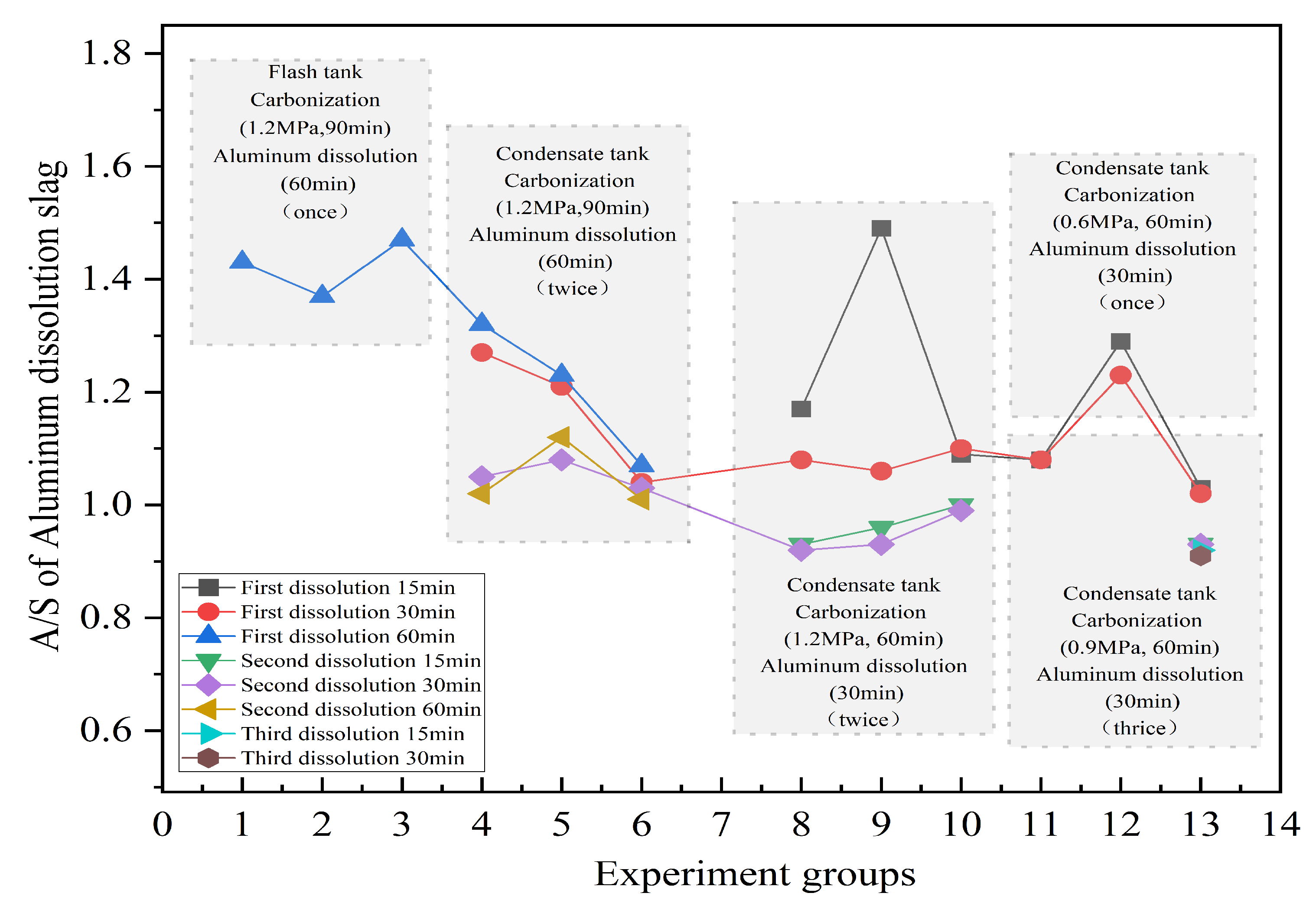
3.2. Carbonization and Aluminum Dissolution

After the bauxite is dissolved via calcination, the dissolved slag is sent from the dissolution system to the settling separation tank for liquid–solid separation when the calcium–silica ratio of the dissolved slag is close to a predetermined value of about 2.75, and the solid phase is used for the subsequent carbonization process. In the carbonization tank, the calcium–silica slag is prepared according to a liquid–solid ratio of 5:1 and fed into the modified carbonization reactor with a feed volume of 800 L. The carbonization reactor is then heated to 120 °C using steam, CO2 is introduced from the modified inlet pipe at the bottom of the reactor, and CO2 gas is used to stir the slurry in the carbonization tank, and the timing starts when the pressure in the carbonization reactor reaches 1.2 MPa. While open, the gas outlet valve at the top of the carbonization reactor keeps the CO2 gas flowing and carries out the carbonization reaction under the condition of ensuring the pressure. After the reaction, the solid–liquid separation of the carbonized slurry was sent to the aluminum dissolution tank for low-temperature dissolution at a reaction temperature of 60 °C, a NaOH concentration of 100 g/L, and a stirring speed of 24 r/min. The effects of carbonization reaction time, carbonization reaction pressure, dissolution time, and the number of times carbonization–aluminum dissolution was performed on the experimental process were verified during the experiment. Figure 7 shows the effect of carbonization–aluminum dissolution under different conditions.
The carbonization reaction tank was made from a flash tank and a condensate tank, and the carbonization reaction was initially carried out in the modified flash tank, but the carbonization effect was much worse than that of the condensate tank from the results of one dissolution of aluminum for 60 min. This is due to the poor stirring effect in the flash tank; the carbonization reaction is not sufficient, so the subsequent carbonization reaction is carried out in the condensate tank. It was found that the effect of dissolving aluminum for 30 min was better than that of 60 min in subsequent experiments, and a study pointed out that too long of a reaction time would cause the aluminum dissolved in the liquid phase to precipitate again to form hydrated garnet, making the A/S of the final residue rise.
The investigation of carbonization time and carbonization reaction pressure revealed that the semi-industrial experiment was better than the laboratory at controlling the temperature and mixing of reaction materials, so a better carbonization effect could be achieved at a carbonization pressure of 0.9 MPa and a reaction time of 60 min. On the other hand, increasing the number of carbonization dissolutions can further reduce the A/S in the final red mud, but the enhancement effect is no longer obvious when increasing to three carbonization dissolutions, so only the second carbonization dissolution is finally determined, and the related results are shown in Table 4.
The results in Table 4 show that after the secondary carbonization–alumina dissolution treatment, the Al/Si ratio in the final red mud can be reduced to 0.85, and the comprehensive alumina recovery rate can reach 81.32%. At the same time, the Na2O mass fraction in the calcined dissolved slag is only 0.95%, which not only reduces the alkali consumption of alumina production, but also reduces the environmental hazards of red mud and can be used as a raw material for other building materials such as cement. For the same grade of bauxite ore, using the traditional Bayer process, the theoretical maximum alumina dissolution rate is 77.1% and the Na2O mass fraction in the slag is about 10.0% (A/S = 1 and N/S = 0.608 in the red mud), while the actual dissolution rate of the Bayer process bauxite ore in this alumina plant is about 70%, which shows that the calcium carbonization method has certain advantages in processing low-grade bauxite ore.
As can be seen from Figure 8, the shape of the original bauxite particles is irregular, mainly in the form of massive and partly lamellar material, which is caused by the bauxite during the grinding process. After calcification, the product morphology changed significantly compared with that of bauxite; the lamellae disappeared and large particles aggregated with spherical small particles with sizes ranging from 1 to 5 m appeared, which is known to be hydrated garnet according to the results of XRD physical phase analysis. During the calcification process of bauxite, minerals such as diaspore and kaolinite are dissolved in the alkali solution, forming aluminate and silicate in the solution and then reacting with calcium hydroxide to produce hydrated garnet, and the main minerals undergo obvious phase transformation. The surface of the spherical hydrated garnet particles in the primary carbonization slag becomes obviously rough, which is the result of the continuous erosion of carbonate in the carbonization process, but the overall spherical morphology of the particles is not destroyed. After the primary alumina dissolution and the subsequent secondary and tertiary alumina dissolution, the spherical shape of the particles in the slag basically disappeared, and there was a smoother surface of large particles of block and plate, which was formed during the carbonization process of calcium carbonate mainly in the form of calcite, and no strip or needle-shaped aragonite-type calcium carbonate was found. During the whole process, bauxite is formed from the initial flaky particles via calcification to spherical hydrated garnet particles, then after the decomposition of the carbonization and aluminum-dissolved process, the spherical hydrated garnet particles are destroyed to form block- and slab-shaped calcium carbonate.
After the above series of experiments, good semi-industrial experimental results were obtained, and the experimental conditions of carbonization and aluminum dissolution were determined as secondary carbonization and aluminum dissolution, in which the experimental conditions of carbonization were as follows: temperature, 120 °C; reaction time, 60 min; liquid–solid ratio, 5:1; CO2 pressure, 0.9 MPa. The experimental conditions of aluminum dissolution were as follows: temperature, 60 °C; reaction time, 30 min; liquid–solid ratio, 10:1; NaOH concentration, 100 g/L. Under optimal conditions, the A/S in the final red mud could be reduced to 0.85 after the second carbonization of alumina dissolution.

4. Conclusions

In this paper, a semi-industrial experiment was conducted on the treatment of low-grade bauxite ore using the calcium carbonization method, and achieved good experimental results using the calcification–carbonization method to treat a typical diaspore bauxite ore in China, which verified the feasibility and advantages of the calcification–carbonization method in industrial production, and further optimized the relevant process parameters:
(1)
The added amount of calcium oxide has a large influence on the calcification dissolution process of bauxite, the mass fraction of Na2O in the calcified slag can be reduced to 0.95% when the ratio of calcium to silicon reaches 2.67:1, and the slag is a single hydrated garnet phase.
(2)
The optimal process conditions for the carbonization process are as follows: temperature, 120 °C; reaction time 60 min; liquid–solid ratio, 5:1; CO2 pressure, 0.9 MPa. the optimal process conditions for the aluminum dissolution process are as follows: temperature, 60 °C; reaction time, 30 min; liquid–solid ratio, 10:1; NaOH concentration, 100 g/L. Under optimal conditions, after the second carbonization–aluminum dissolution, the A/S in the final red mud can be reduced to 0.85, and the actual dissolution rate of alumina in bauxite can reach 81.32%.

Author Contributions

Y.C.: data curation, funding acquisition, resources. F.L.: software. X.C.: investigation, original draft preparation. Y.L.: validation, investigation. W.Z.: investigation. T.Z.: methodology, supervision. G.L.: review and editing. All authors have read and agreed to the published version of the manuscript.

Funding

This research was funded by the National Natural Science Foundation of China (51874078); Guangxi Science and Technology Base and Talent Special (Guike AD 22035105); Open foundation of state environmental protection key laboratory of mineral metallurgical resources utilization and pollution control (HB202105).

Informed Consent Statement

All authors have read and agreed to the published version of the manuscript.

Data Availability Statement

Not applicable.

Acknowledgments

This research was supported by the National Natural Science Foundation of China (No. 52204358); Guangxi Science and Technology Base and Talent Special (Guike AD 22035105); Open foundation of state environmental protection key laboratory of mineral metallurgical resources utilization and pollution control (HB202105).

Conflicts of Interest

The authors declare that they have no known competing financial interest or personal relationships that could have appeared to influence the work reported in this paper.

References

  1. USGS. Geological Survey Mineral Commodity Summaries; U.S. Geological Survey: Reston, VA, USA, 2022. [Google Scholar]
  2. Smičiklas, I.; Jović, M.; Janković, M.; Smiljanić, S.; Onjia, A. Environmental safety aspects of solid residues resulting from acid mine drainage neutralization with fresh and aged bauxite residue. Water Air Soil Pollut. 2021, 232, 324–338. [Google Scholar] [CrossRef]
  3. Ding, J.; Ma, S.; Shen, S.; Xie, Z.; Zheng, S.; Zhang, Y. Research and industrialization progress of recovering alumina from fly ash: A concise review. Waste Manag. 2017, 60, 357–387. [Google Scholar] [CrossRef] [PubMed]
  4. Cao, H.; Zhang, Y.F.; Zhang, Y. Preparation of sodium aluminate from the leach liquor of diasporic bauxite in concentrated NaOH solution. Hydrometallurgy 2009, 98, 298–303. [Google Scholar] [CrossRef]
  5. Nikbin, I.M.; Aliaghazadeh, M.; Charkhtab, S.H.; Fathollahpour, A. Environmental impacts and mechanical properties of lightweight concrete containing bauxite residue (red mud). J. Clean. Prod. 2018, 172, 2683–2694. [Google Scholar] [CrossRef]
  6. Lemougna, P.N.; Wang, K.T.; Tang, Q.; Cui, X.M. Study on the development of inorganic polymers from red mud and slag system: Application in mortar and lightweight materials. Constr. Build. Mater. 2017, 156, 486–495. [Google Scholar] [CrossRef]
  7. Li, Y.C.; Min, X.B.; Ke, Y.; Chai, L.Y.; Shi, M.Q.; Tang, C.J.; Wang, Q.W.; Liang, Y.J.; Lei, J.; Liu, D.G. Utilization of red mud and Pb/Zn smelter waste for the synthesis of a red mud-based cementitious material. J. Hazard. Mater. 2018, 344, 343–349. [Google Scholar] [CrossRef]
  8. Bhatnagar, A.; Vilar, V.J.; Botelho, C.M.; Boaventura, R.A. A review of the use of bauxite residue as adsorbent for the removal of toxic pollutants from water and wastewater. Environ. Technol. 2011, 32, 231–249. [Google Scholar] [CrossRef] [PubMed]
  9. Zhu, X.F.; Zhang, T.A.; Lü, G.Z. Kinetics of carbonated decomposition of hydro garnet with different silica saturation coefficients. Int. J. Miner. Metall. Mater. 2020, 27, 472–482. [Google Scholar] [CrossRef]
  10. Brunori, C.; Cremisini, C.; Massanisso, P.; Pinto, V.; Torricelli, L. Reuse of a treated bauxite residue bauxite waste: Studies on environmental compatibility. J. Hazard. Mater. 2005, 117, 55–63. [Google Scholar] [CrossRef]
  11. Teng, F. An introduction to the smelting technology and development trend of alumina and electrolytic aluminum. World Nonferr. Met. 2019, 2, 56–62. [Google Scholar]
  12. Lu, G.; Zheng, C.; Zhu, X.; Zhang, W.; Wang, Y. The influence of the silicon saturation coefficient on a calcification carbonization method for clean and efficient use of bauxite. Hydrometallurgy 2017, 174, 97–104. [Google Scholar] [CrossRef]
  13. Gelencsér, A.; Kováts, N.; Turóczi, B.; Rostási, Á.; Hoffer, A.; Imre, K.; Nyirő-Kósa, I.; Csákberényi-Malasics, D.; Tóth, Á.; Czitrovszky, A. The Bauxite residue accident in Ajka (Hungary): Characterization and potential health effects of fugitive dust. Environ. Sci. Technol. 2011, 45, 1608–1615. [Google Scholar] [CrossRef] [PubMed]
  14. Chen, Y.; Zhang, T.A.; Lv, G.; Chao, X.; Yang, X. Response of soil microbial communities to bauxite residue-based stabilizer remediation of cadmium-contaminated farmland. Environ. Sci. Pollut. Res. 2018, 109, 180–185. [Google Scholar]
  15. Liu, Y.; Naidu, R. Hidden values in bauxite residue (bauxite residue): Recovery of metals. Waste Manag. 2014, 156, 164–173. [Google Scholar]
  16. Lu, G.; Zhang, T.A.; Zhu, X.; Liu, Y.; Wang, Y.; Guo, F.; Zhao, Q.; Zheng, C. Calcification–carbonization method for cleaner alumina production and CO2 utilization. JOM 2014, 66, 1616–1621. [Google Scholar] [CrossRef]
  17. Luo, L.D. Applying study on the Bayer bauxite residue as fast building dam materials. Adv. Mater. Res. 2013, 671–674, 1725–1728. [Google Scholar] [CrossRef]
  18. Qi, L.; Ou, S.; Wang, Q. The Comprehensive Energy saving in China Alumina Industry. Light Met. 2005, 16, 35–40. [Google Scholar]
  19. Mymrin, V.A.; Vázquez-Vaamonde, A.J. Bauxite residue of aluminum production waste is a basic component of new construction materials. Waste Manag. Res. J. Int. Solid Wastes Public Clean. Assoc. Iswa 2001, 19, 465. [Google Scholar] [CrossRef]
  20. Li, R.B.; Zhang, T.A.; Liu, Y.; Lv, G.; Xie, L. Calcification-carbonization method for bauxite residue processing. J. Hazard. Mater. 2016, 316, 94–101. [Google Scholar] [CrossRef]
  21. Zhang, T.; Guozhi, L.V.; Liu, Y.; Zhang, Z.; Zhu, X.; Zhihe, D.O.U. Method for Recovering Alkali and Aluminum in Course of Treatment of Bayer Bauxite Residue by Using Calcification-Carbonization Method. US9963353, 30 April 2018. [Google Scholar]
  22. Ke, W.; Zhang, X.; Zhu, F.; Wu, H.; Zhang, Y.; Shi, Y.; Hartley, W.; Xue, S. Appropriate human intervention stimulates the development of microbial communities and soil formation at a long-term weathered bauxite residue disposal area. J. Hazard. Mater. 2021, 405, 124–138. [Google Scholar] [CrossRef]
  23. Xue, S.; Liu, Z.; Fan, J.; Xue, R.; Guo, Y.; Chen, W.; Hartley, W.; Zhu, F. Insights into variations on the dissolved organic matter of bauxite residue during soil-formation processes following 2-year column simulation. Environ. Pollut. 2022, 292, 118–126. [Google Scholar] [CrossRef] [PubMed]
  24. Liu, Z.; Li, H. Metallurgical Process for Valuable elements recovery from bauxite residue—A review. Hydrometallurgy 2015, 155, 29–43. [Google Scholar] [CrossRef]
Figure 1. Schematic diagram of the semi-industrial test of the calcification–carbonization method.
Separations 10 00336 g001
Figure 2. XRD patterns of raw bauxite.
Separations 10 00336 g002
Figure 3. SEM images of raw bauxite (a) × 5 K; (b) × 50 K.
Separations 10 00336 g003
Figure 4. Variation trend diagram of calcification-dissolved solid phase composition. (Temperature, 265 °C; calcium–silica ratio, 2.75:1; liquid–solid ratio, 5:1; alkali concentration of sodium aluminate solution, 265~270 g/L.)
Separations 10 00336 g004
Figure 5. Variation trend of liquid phase composition in different process stages. (a) Trend graph of raw ore slurry composition; (b) trend graph of dissolved slurry composition; (c) trend graph of red mud wash composition.
Separations 10 00336 g005
Figure 6. XRD pattern analysis of calcified slag with different C/S.
Separations 10 00336 g006
Figure 7. The results of carbonization–aluminum dissolution experiments under different conditions.
Separations 10 00336 g007
Figure 8. SEM images of different samples. (a) Bauxite; (b) calcified slag; (c) primary carbonized slag; (d) primary aluminum-dissolved slag; (e) secondary carbonized slag; (f) secondary aluminum-dissolved slag; (g) tertiary carbonized slag; (h) tertiary aluminum-dissolved slag.
Separations 10 00336 g008
Table 1. Chemical composition of bauxite (mass fraction/%).
IngredientsAl2 O3SiO2CaOFe2O3TiO2Na2OBurn LossA/S
Content61.6013.530.905.063.250.3418.604.55
Table 2. Related equipment and specifications.
Equipment NameSpecificationVolume
Raw material millΦ2.4*8 m
Dwell poolΦ8*10 m
1# desilicon tankΦ6*13.5 m Effective liquid level 12.2 m341 m3
2# desilicon tankΦ6*13 m Effective liquid level 11.7 m327 m3
Settlement separation tankOperating level 10 m
Carbonization reaction tankEffective/operating level 10.2 m/7 m Φ6*11 m285/196 m3
Aluminum dissolution tankEffective/operating level 3 m/2.5 m Φ3*3 m
Tube digestion2-φ114*11 L = 80 m Run 4042.5 m3
Insulated dwell tanksΦ1.8 m*20 m Run 4pcs45 m3
Diaphragm PumpsMaximum flow rate of 75 m3/h for a single unit, operating 3 units at 30 Hz, total flow rate 135 m3/h
Table 3. The composition of the calcified slag at different times (mass fraction/%).
Sample NumberAl2O3SiO2Fe2O3TiO2K2ONa2OCaOMgOA/SN/SC/S
122.3620.487.944.251.315.7621.380.971.090.281.04
221.6518.426.783.70.764.4227.131.131.180.241.47
321.2117.026.663.430.563.4430.161.181.250.201.77
420.8116.366.23.190.462.5132.71.341.270.152.00
520.4415.785.572.860.282.0335.041.061.300.132.22
620.9114.754.362.580.191.337.161.171.420.092.52
720.7114.424.472.560.130.9538.461.141.440.072.67
Table 4. The results of repeated carbonization–aluminum dissolution experiments.
Carbonization–Aluminum
Dissolution Times
Results
Al2O3/%SiO2/%A/SDissolution Rate/%
113.9214.430.9678.9
211.8113.890.8581.32
310.5812.890.8281.98
Disclaimer/Publisher’s Note: The statements, opinions and data contained in all publications are solely those of the individual author(s) and contributor(s) and not of MDPI and/or the editor(s). MDPI and/or the editor(s) disclaim responsibility for any injury to people or property resulting from any ideas, methods, instructions or products referred to in the content.

