
Effect of Scale-Up on Residence Time and Uranium Extraction on Annular Centrifugal Contactors (ACCs)


Abstract
:
1. Introduction
- high shear,
- high-efficiency mixing zone,
- an enhanced separation zone, using centrifugal force that is 200× greater than gravity.
2. Materials and Methods
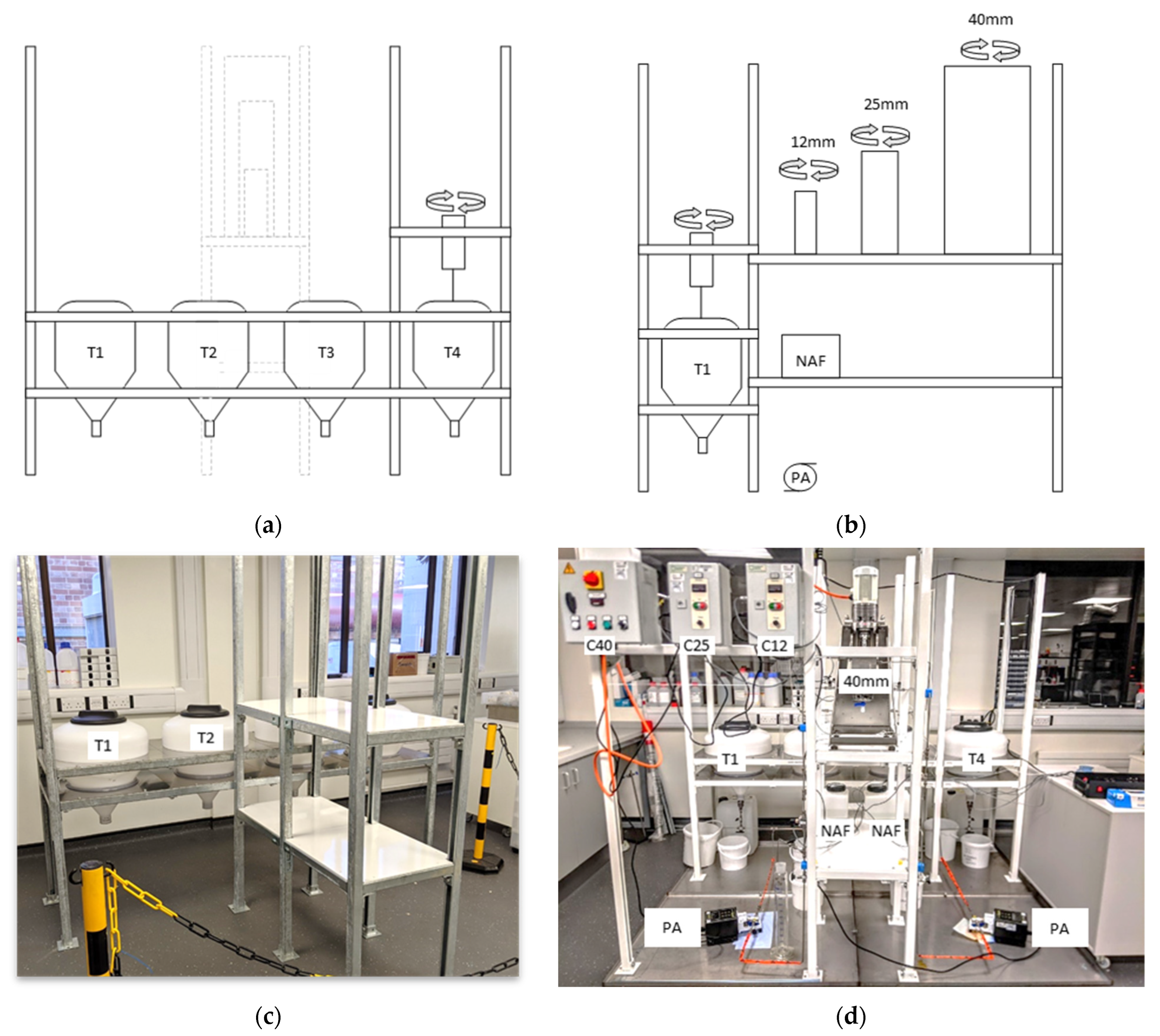
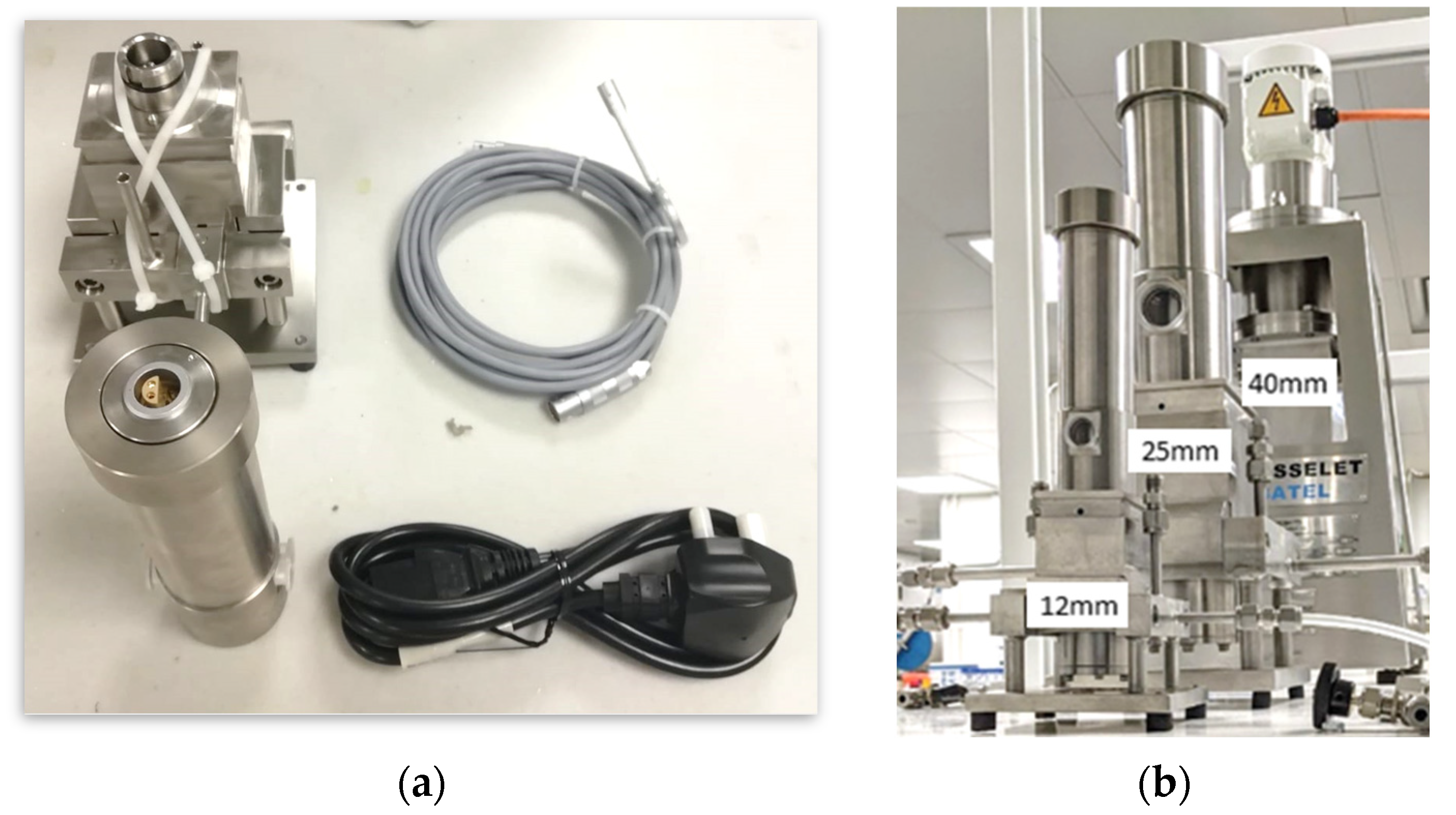
2.1. Construction of the Multi-Scale Contactor Rig
- 12 mm RD,
- 25 mm RD,
- 40 mm RD.
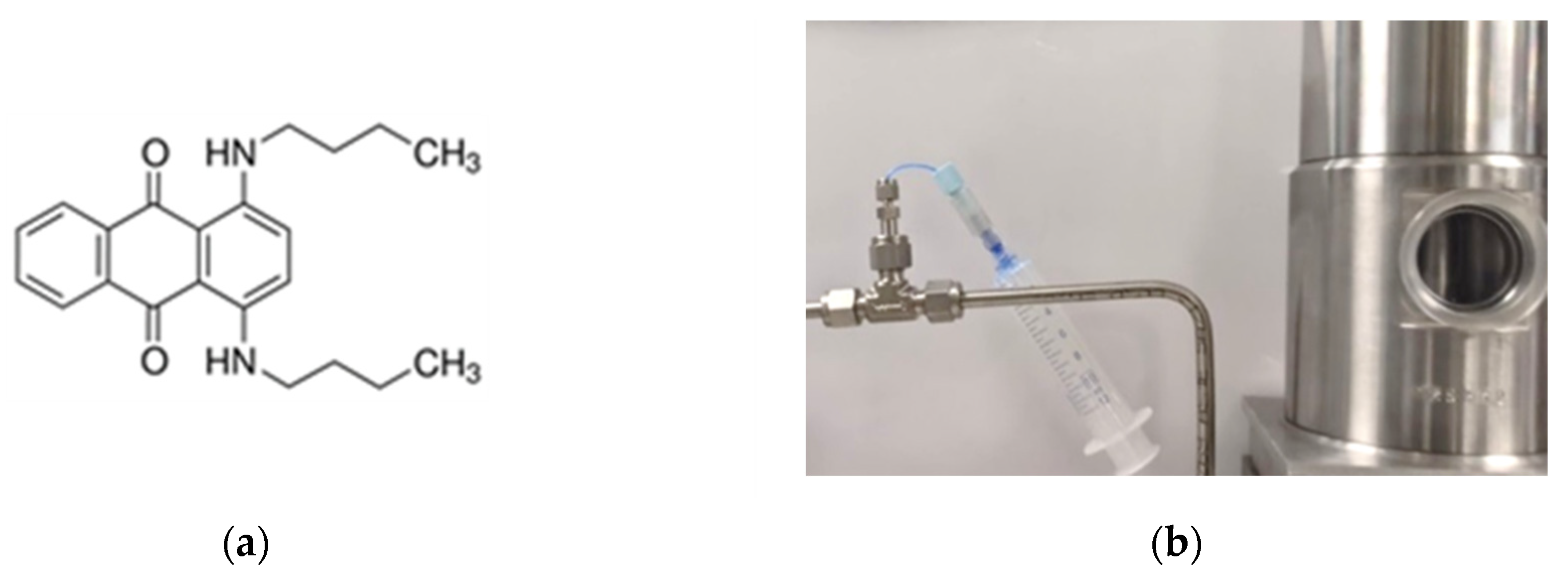
2.2. Materials
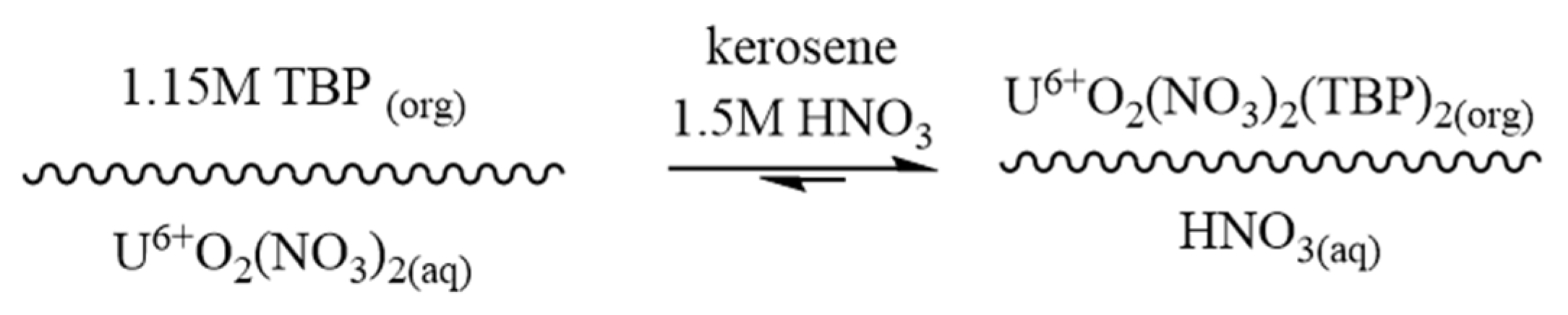
2.3. Uranium Solvent Extraction Batch Test
2.4. UV Vis Spectrometer
2.5. Titrations
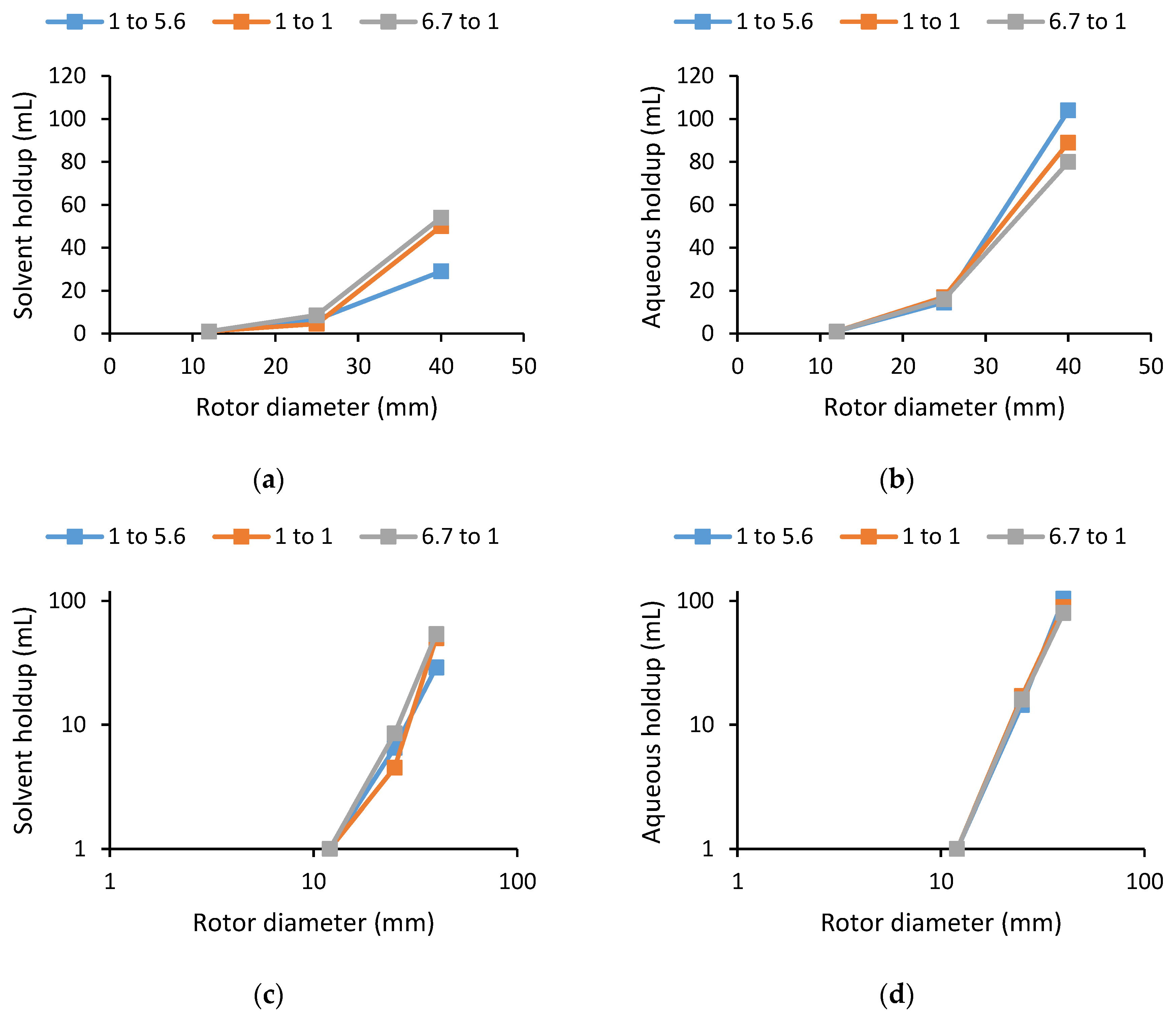
2.6. Residence Time Distribution Experiments and Liquid Holdup within ACC Housings
2.7. Uranium Solvent Extraction with ACCs
2.8. Working with Open Sources of Ionising Radiation
- Careful dispensing and handling of any material to minimize the risk of contamination.
- Immediate disposal of any contaminated tips, syringes, etc.
- Containment of any samples created in a secondary container such as a plastic bag or box.
- Storage or disposal of any stocks and samples not in use as soon as practicable.
- A radiation monitor is used to identify any contaminated areas or equipment.
3. Results and Discussion
- Residence time
- Volumetric holdup
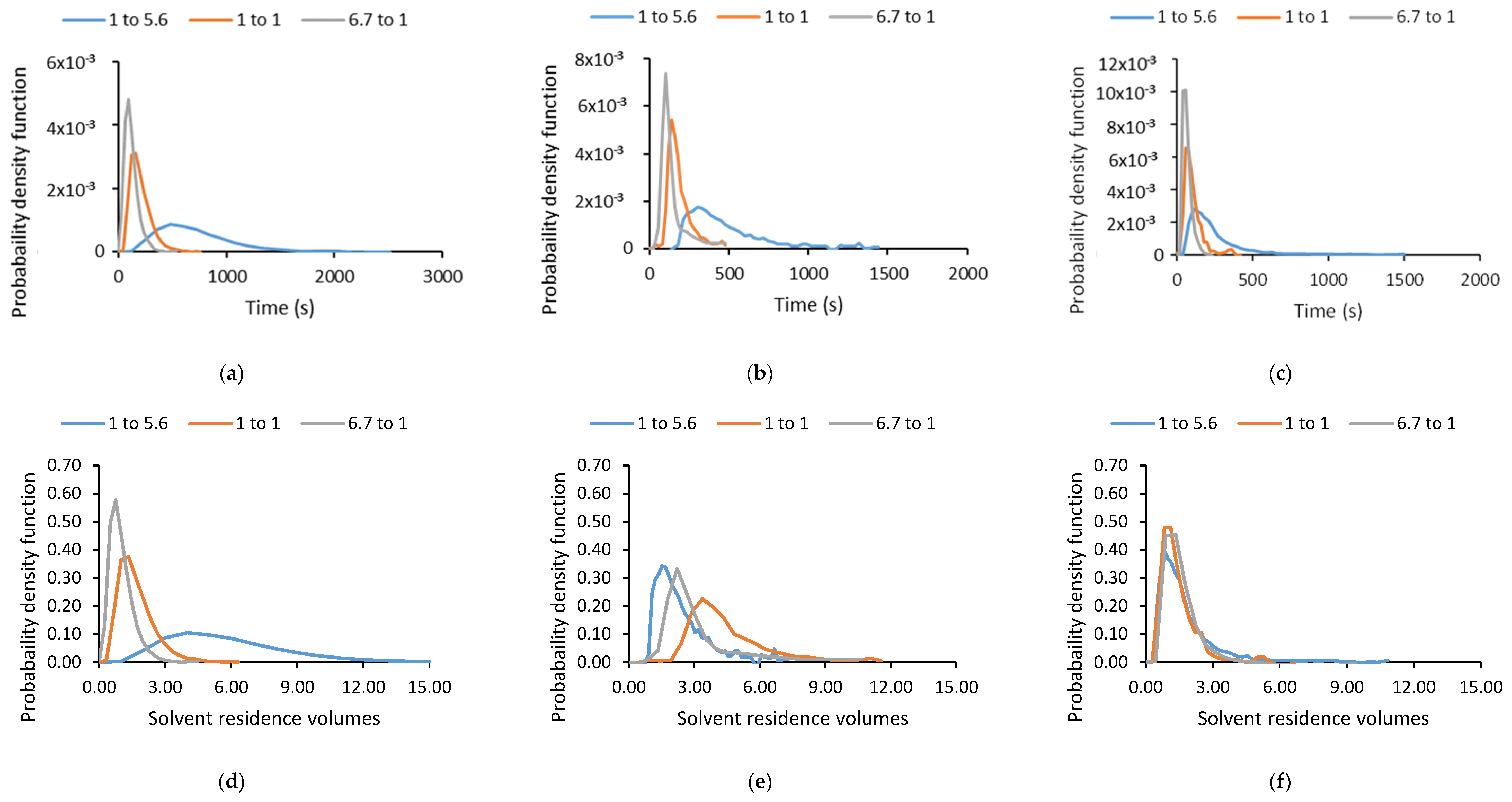
- Residence time distribution
- Extraction stage efficiency of uranium (in the species of uranyl nitrate item)
Measurement of Stage Efficiency of Uranium Extractions
([U]final solvent X Solvent.Volume))
4. Conclusions
Author Contributions
Funding
Acknowledgments
Conflicts of Interest
Acronyms
| ACC | Annular Centrifugal Contactors |
| RTD | Residence Time Distribution |
| RD | Rotor Diameter |
| IUPAC | International Union of Pure and Applied Chemistry |
| LLE | Liquid-Liquid Extraction |
| PUREX | Plutonium Uranium Reduction Extraction |
| MSCR | Multi-Scale Contactor Rig |
| TBP | Tributyl Phosphate |
| S/A | Solvent/Aqueous Ratio |
| RPM | Revolutions per minute |
| SE | Stage Efficiency |
| EPSRC | Engineering and Physical Sciences Research Council |
| BEIS | Department for Business, Energy and Industrial Strategy’s |
References
- Leigh, G.J. Principles of Chemical Nomenclature: A Guide to IUPAC Recommendations; Royal Society of Chemistry: London, UK, 2011. [Google Scholar]
- Rice, N.M.; Irving, H.M.N.H.; Leonard, M.A. Nomenclature for liquid-liquid distribution (solvent extraction) (IUPAC Recommendations 1993). Pure Appl. Chem. 1993, 65, 2373–2396. [Google Scholar] [CrossRef]
- Tessier, A.; Campbell, P.G.; Bisson, M. Sequential extraction procedure for the speciation of particulate trace metals. Anal. Chem. 1979, 51, 844–851. [Google Scholar] [CrossRef]
- Stankiewicz, A.I.; Moulijn, J.A. Process intensification: Transforming chemical engineering. Chem. Eng. Prog. 2000, 96, 22–34. [Google Scholar]
- Hamamah, Z.A.; Grützner, T. Liquid-Liquid Centrifugal Extractors: Types and Recent Applications—A Review. ChemBioEng Rev. 2022, 9, 286–318. [Google Scholar] [CrossRef]
- Xu, C.; Xie, T. Review of microfluidic liquid–liquid extractors. Ind. Eng. Chem. Res. 2017, 56, 7593–7622. [Google Scholar] [CrossRef]
- Baker, A.; De Santis, A.; Fells, A.; Hunter, T.; Hanson, B.C.; Maher, C.; Taylor, R. The development of centrifugal contactors: Next generation solvent extraction equipment for advanced reprocessing of nuclear fuels. Nucl. Future 2022, 3, 38–54. [Google Scholar]
- Barron, N. A ‘fast’ approach to net zero. Nucl. Future 2021, 17, 39–45. [Google Scholar]
- Goddard, D.T. Recent progress in accident tolerant fuels. Nucl. Future 2017, 13, 40–44. [Google Scholar]
- Nevitt, P.; Sherock, M.; Vernon, E. Fuelling Net Zero—The UK Advanced Fuel Cycle Programme (AFCP). Nucl. Future 2021, 17, 45–54. [Google Scholar]
- Baker, A.; Fells, A.; Carrott, M.J.; Maher, C.J.; Hanson, B.C. Process intensification of element extraction using centrifugal contactors in the nuclear fuel cycle. Chem. Soc. Rev. 2022, 51, 3964–3999. [Google Scholar] [CrossRef]
- Taylor, R. The Chemical Basis for Separating Recycling Materials by Hydro-Processes; Elsevier: Amsterdam, The Netherlands, 2021. [Google Scholar]
- Law, J.; David, M.; Troy, G.; Nick, M.; Scott, H. The testing of commercially available engineering and plant scale annular centrifugal contactors for the processing of spent nuclear fuel. In Proceedings of the 15th Pacific Basin Nuclear Conference, Sydney, Australia, 15–20 October 2006; Australian Nuclear Association: Sydney, Australia, 2006. [Google Scholar]
- Vedantam, S.; Joshi, J. Annular centrifugal contactors—A review. Chem. Eng. Res. Des. 2006, 84, 522–542. [Google Scholar] [CrossRef]
- Webster, D.; Jennings, A.S.; Kishbaugh, A.A.; Bethmann, H.K. Performance of Centrifugal Mixer-Settler in the Reprocessing of Nuclear Fuel. In Symposium on Recent Advances in Reprocessing of Irradiated Fuel American Institute of Chemical Engineers Meeting; Du Pont de Nemours (EI) and Co., Aiken, SC Savannah River Lab: New York, NY, USA, 1967. [Google Scholar]
- Bernstein, G.J.; Grosvenor, D.E.; Lenc, J.F.; Levitz, N.M. Development and Performance of a High-Speed, Long-Rotor Centrifugal Contactor for Application to Reprocessing LMFBR Fuels; ANL-7968; Argonne National Laboratory: Lemont, IL, USA, 1973; p. 52. [Google Scholar]
- Miller, J.M.J. Solvent Extraction and Mass Transfer Assessment in Novel Extraction Technologies; University of Leeds: Leeds, UK, 2021. [Google Scholar]
- Jenkins, J.A.; Thompson, P.J.; Jubin, R.T. Performance of centrifugal contactors on uranium and plutonium active PUREX flowsheets. In Proceedings of the International Solvent Extraction Conference, York, UK, 9–15 September 1993. [Google Scholar]
- Birkett, J.; Carrot, M.J.; Fox, O.D.; Maker, C.J.; Route, C.V. Plutonium and Neptunium Stripping in Single Cycle Solvent Extraction Flowsheets: Recent Progress in Flowsheet Testing; Nuclear Sciences and Technology Services: Sellafield, UK, 2004. [Google Scholar]
- Birkett, J.; Carrott, M.J.; Crooks, G.; Fox, O.D. Purex Process Improvements for PU and NP Control in Total Actinide Recycle Flowsheets. In Proceedings of the Waste Management Symposium, Tucson, AR, USA, 23–25 October 2006; pp. 1–11. [Google Scholar]
- Carrott, M.J.; Fox, O.D.; Maher, C.J.; Mason, C.; Taylor, R.J.; Sinkov, S.I.; Choppin, G.R. Solvent extraction behavior of plutonium (IV) ions in the presence of simple hydroxamic acids. Solvent Extr. Ion Exch. 2007, 25, 723–745. [Google Scholar] [CrossRef]
- Fox, O.; Carrott, M.J.; Gaubert, E.; Woodhead, D.A. Development and validation of process models for minor actinide separations processes using centrifugal contactors. In Proceedings of the 7th International Conference on Advanced Nuclear Fuel Cycles and Systems (GLOBAL 2007), Boise, ID, USA, 9–13 September 2007. [Google Scholar]
- Carrott, M.; Geist, A.; Hères, X.; Lange, S.; Malmbeck, R.; Miguirditchian, M.; Modolo, G.; Wilden, A.; Taylor, R. Distribution of plutonium, americium and interfering fission products between nitric acid and a mixed organic phase of TODGA and DMDOHEMA in kerosene, and implications for the design of the “EURO-GANEX” process. Hydrometallurgy 2015, 152, 139–148. [Google Scholar] [CrossRef]
- May, I.; Birkett, E.J.; Denniss, I.S.; Gaubert, E.T.; Jobson, M. Mass Transfer Trials on U (VI) and Np (IV) in a Single Stage Centrifugal Contactor. In Atalante 2000; CEA Marcoule: Chusclan, France, 2000. [Google Scholar]
- Carrott, M.J.; Maher, C.J.; Mason, C.; Sarsfield, M.J.; Whittaker, D.; Taylor, R.J. Experimental Test of a Process Upset in the EURO-GANEX Process and Spectroscopic Study of the Product. Solvent Extr. Ion Exch. 2022, 41, 88–117. [Google Scholar] [CrossRef]
- Wilden, A.; Modolo, G.; Schreinemachers, C.; Sadowski, F.; Lange, S.; Sypula, M.; Magnusson, D.; Geist, A.; Lewis, F.W.; Harwood, L.M.; et al. Direct selective extraction of actinides (III) from PUREX raffinate using a mixture of CyMe4BTBP and TODGA as 1-cycle SANEX solvent part III: Demonstration of a laboratory-scale counter-current centrifugal contactor process. Solvent Extr. Ion Exch. 2013, 31, 519–537. [Google Scholar] [CrossRef]
- Duan, W.; Zhou, X.; Zhang, C. Extraction of Hydrocortisone from the Fermentation Liquor with Annular Centrifugal Contactors. Sep. Sci. Technol. 2006, 41, 573–581. [Google Scholar]
- Bergeonneau, P.; Jaouen, C.; Germain, M.; Bathellier, A. Uranium, neptunium and plutonium kinetics of extraction by tributylphosphate and trilaurylamine in a centrifugal contactor. In Proceedings of the International Solvent Extraction Conference (ISEC-77), Toronto, ON, Canada, 9–16 September 1977; Lucas, B.H., Smith, H.W., Eds.; CEA Centre d’Etudes Nucleaires de Fontenay-aux-Roses: Toronto, ON, Canada, 1977; p. 612. [Google Scholar]
- Verlinden, B.; Wilden, A.; Van Hecke, K.; Egberink, R.J.M.; Huskens, J.; Verboom, W.; Hupert, M.; Weßling, P.; Geist, A.; Panak, P.J.; et al. Solvent Optimization Studies for a New EURO-GANEX Process with 2, 2′-Oxybis (N, N-di-n-decylpropanamide)(mTDDGA) and Its Radiolysis Products. Solvent Extr. Ion Exch. 2023, 41, 59–87. [Google Scholar] [CrossRef]
- Leonard, R. Prediction of Hydraulic Performance in Annular Centrifugal Contactors; Argonne National Lab: Lemont, IL, USA, 1980. [Google Scholar]
- Siczek, A.A.; Meisenhelder, J.H.; Bernstein, G.J.; Steindler, M.J. Solvent extraction studies in miniature centrifugal contactors. Radiochim. Acta 1980, 27, 51–60. [Google Scholar] [CrossRef]
- De Santis, A.; Colombo, M.; Hanson, B.; Fairweather, M. A generalized multiphase modelling approach for multiscale flows. J. Comput. Phys. 2021, 436, 110321. [Google Scholar] [CrossRef]
- De Santis, A.; Hanson, B.; Fairweather, M. Hydrodynamics of Annular Centrifugal Contactors: A CFD analysis using a novel multiphase flow modelling approach. Chem. Eng. Sci. 2021, 242, 116729. [Google Scholar] [CrossRef]
- Colombo, M.; De Santis, A.; Hanson, B.C.; Fairweather, M. A novel generalized multifluid modelling approach for the simulation of multiphase flows: Model development and validation. In Proceedings of the 13th International European Research Community on Flow, Turbulence and Combustion (ERCOFTAC) Symposium, Rhodes, Greece, 15–17 September 2021; Springer: Berlin/Heidelberg, Germany, 2021. [Google Scholar]
- De Santis, A.; Colombo, M.; Hanson, B.C.; Fairweather, M. A novel generalized multifluid modelling approach for the simulation of multiphase flows: Application to intensified liquid-liquid extraction. In Proceedings of the 13th International European Research Community on Flow, Turbulence and Combustion (ERCOFTAC) Symposium, Rhodes, Greece, 15–17 September 2021; Springer: Berlin/Heidelberg, Germany, 2021. [Google Scholar]
- Fells, A.; De Santis, A.; Colombo, M.; Theobald, D.W.; Fairweather, M.; Muller, F.; Hanson, B. Predicting Mass Transfer in Liquid-Liquid Extraction Columns. Processes 2022, 10, 968. [Google Scholar] [CrossRef]
- De Santis, A.; Colombo, M.; Hanson, B.C.; Fairweather, M. Hydrodynamics and mass transfer in multiscale multiphase flows: A novel CFD modelling approach. In Proceedings of the 19th International Topical Meeting on Nuclear Reactor Thermal Hydraulics (NURETH-19), Brussels, Belgium, 6–11 March 2022; Sheffield American Nuclear Society: Sheffield, UK, 2022. [Google Scholar]
- Taylor, R.; Mathers, G. Innovation in the aqueous recycle of spent nuclear fuels. Nucl. Future 2019, 15, 40–48. [Google Scholar]
- Miao, Q.; Sun, T.; Zheng, Q.; Zhang, Y.; Duan, W. Effects of the Structure, Operation, and Physical Parameters on the Actual Phase Ratio and Interface Radius in the Separation Zone of an Annular Centrifugal Contactor. Ind. Eng. Chem. Res. 2023, 62, 637–648. [Google Scholar] [CrossRef]
- Bertelsen, E.R.; Antonio, M.R.; Jensen, M.P.; Shafer, J.C. Electrochemistry of PUREX: R is for reduction and ion transfer. Solvent Extr. Ion Exch. 2022, 40, 64–85. [Google Scholar] [CrossRef]


| Rotor Diameter | 12 | 25 | 40 | mm |
|---|---|---|---|---|
| Maximum rotor speed | 10,000 | 4000 | 3000 | RPM |
| (670) | (223) | (200) | (G) | |
| Bowl volume | 2.2 | 19 | 110 | mL |
| Heavy phase weir | 7.5 | 15.5 | 25.5 | mm |
| Maximum total throughput | 33 | 166 | 833 | mL/min |
| Minimum total throughput | >3.3 | 13 | 83 | mL/min |
| Vanes in mixing zone | 4 | 6 | 6 | - |
| Height | 295 | 482 | 792 | mm |
| Width | 100 | 170 | 312 | mm |
| Weight | 5 | 25 | 50 | kg |
| Entry | Rotor Diameter (mm) | Total Throughput (mL/min) | Rotor Speed (RPM) | S/A Ratio | Number of Repeats | Solvent Holdup (mL) | Aqueous Holdup (mL) |
|---|---|---|---|---|---|---|---|
| 1 | 12 | 3.3 | 9500 | 1:1 | 3 | 1.0 | 1.0 |
| 2 | 12 | 3.3 | 1:5.6 | 1 | 1.0 | 1.0 | |
| 3 | 12 | 3.3 | 6.7:1 | 1 | 1.0 | 1.0 | |
| 4 | 25 | 13.0 | 3500 | 1:1 | 3 | 4.5 | 17.0 |
| 5 | 25 | 13.0 | 1:5.6 | 1 | 6.5 | 14.5 | |
| 6 | 25 | 13.0 | 6.7:1 | 1 | 8.5 | 16.0 | |
| 7 | 40 | 83.0 | 2500 | 1:1 | 3 | 50.0 | 89.0 |
| 8 | 40 | 83.0 | 1:5.6 | 1 | 29.0 | 104.0 | |
| 9 | 40 | 83.0 | 6.7:1 | 1 | 54.0 | 80.0 |
| Rotor Diameter (mm) | Experimentally Derived Liquid Holdup (mL) | 4% by Volume Dye Injection (mL) |
|---|---|---|
| 12 | 2.7 | 0.1 |
| 25 | 25.3 | 1.0 |
| 40 | 143.0 | 5.5 |
| Entry | Rotor Diameter (mm) | S/A Ratio | Measured Total Throughput (mL/min) | Rotor Speed (RPM) |
|---|---|---|---|---|
| 1 | 12 | 2.1:1 | 1.5 | 9500 |
| 2 | 25 | 2.0:1 | 14.5 | |
| 3 | 40 | 2.4:1 | 80.5 | 3500 |
| 4 | 12 | 1:7.1 | 3.5 | |
| 5 | 25 | 1:6.4 | 13.8 | 2500 |
| 6 | 40 | 1:5.8 | 81.7 |
| Time (min) | |||||
|---|---|---|---|---|---|
| 25 | 45 | 65 | 85 | 105 | |
| S.E. | 93% | 97% | 96% | 97% | 96% |
| M.B. | 84% | 89% | 90% | 90% | 89% |
| Time (min) | |||||
|---|---|---|---|---|---|
| 20 | 25 | 30 | 35 | 40 | |
| S.E. | 97% | 98% | 99% | 99% | 99% |
| M.B. | 104% | 95% | 97% | 94% | 96% |
| Time (min) | ||||
|---|---|---|---|---|
| 25 | 27 | 29 | 33 | |
| S.E. | 97% | 98% | 98% | 98% |
| M.B. | 113% | 109% | 110% | 110% |
| Time (min) | |||||
|---|---|---|---|---|---|
| 20 | 25 | 30 | 35 | 40 | |
| S.E. | 93% | 97% | 96% | 97% | 96% |
| M.B. | 90% | 94% | 93% | 94% | 93% |
| Time (min) | |||||
|---|---|---|---|---|---|
| 40 | 50 | 55 | 60 | 40 | |
| S.E. | 90% | 87% | 91% | 96% | 90% |
| M.B. | 92% | 91% | 90% | 107% | 92% |
| Time (min) | ||||||
|---|---|---|---|---|---|---|
| 25 | 27.5 | 30 | 32.5 | 35 | 38.5 | |
| S.E. | 97% | 97% | 99% | 98% | 99% | 99% |
| M.B. | 112% | 108% | 111% | 109% | 110% | 107% |
Disclaimer/Publisher’s Note: The statements, opinions and data contained in all publications are solely those of the individual author(s) and contributor(s) and not of MDPI and/or the editor(s). MDPI and/or the editor(s) disclaim responsibility for any injury to people or property resulting from any ideas, methods, instructions or products referred to in the content. |
© 2023 by the authors. Licensee MDPI, Basel, Switzerland. This article is an open access article distributed under the terms and conditions of the Creative Commons Attribution (CC BY) license (https://creativecommons.org/licenses/by/4.0/).
Share and Cite
Baker, A.; Fells, A.; Shaw, T.; Maher, C.J.; Hanson, B.C. Effect of Scale-Up on Residence Time and Uranium Extraction on Annular Centrifugal Contactors (ACCs). Separations 2023, 10, 331. https://doi.org/10.3390/separations10060331
Baker A, Fells A, Shaw T, Maher CJ, Hanson BC. Effect of Scale-Up on Residence Time and Uranium Extraction on Annular Centrifugal Contactors (ACCs). Separations. 2023; 10(6):331. https://doi.org/10.3390/separations10060331
Chicago/Turabian StyleBaker, Alastair, Alex Fells, Thomas Shaw, Chris J. Maher, and Bruce C. Hanson. 2023. "Effect of Scale-Up on Residence Time and Uranium Extraction on Annular Centrifugal Contactors (ACCs)" Separations 10, no. 6: 331. https://doi.org/10.3390/separations10060331