


Conceptual Design of a Compact Water Purification Unit Using Reed Bed Filtration


1
Department of Civil Engineering, School of Engineering, Holy Spirit University of Kaslik (USEK), Jounieh P.O. Box 446, Lebanon
2
Environmental Engineering and Sustainability Management, École Polytechnique, CEDEX, 91128 Palaiseau, France
*
Author to whom correspondence should be addressed.
Separations 2023, 10(3), 194; https://doi.org/10.3390/separations10030194
Submission received: 22 February 2023
/
Revised: 5 March 2023
/
Accepted: 6 March 2023
/
Published: 12 March 2023
(This article belongs to the Topic Sustainable Water Purification Technologies for Multiple Applications)
Abstract
:One of the most widespread global challenges is the insufficient provision of potable water, which affects individuals across diverse geographical regions. It is anticipated that issues related to water scarcity and quality will escalate in tandem with the expanding human population and the rapid pace of global development. Water sources are massively polluted hence, not safe for drinking nor irrigation. As a consequence, it is very important to have a water purification treatment plant to provide good water quality. Given the pressing need to ensure universal access to safe and clean drinking water, this investigation aims to engineer a compact and space-efficient apparatus that can expeditiously produce purified water. The proposed system seeks to optimize water purification performance while minimizing spatial requirements and operational duration. Its size is minimized by combining the three processes: coagulation, flocculation, and clarification together in one tank. Following to the aforementioned reservoir, an integrated natural system is employed to reduce the usage of chemicals and establish an ecologically sustainable platform. A hydraulic study is conducted to obtain the dimensioning of the several units which can be later scaled according to the flowrate. The latter was assumed in this study to be 2 L/s, then the compact unit can serve up to 800 persons by scaling the model and adjusting it.
1. Introduction
Access to clean and safe water is essential for human survival and well-being. However, in many parts of the world, access to clean water is limited or non-existent, particularly in developing countries and rural areas. The scarcity of unpolluted water can engender far-reaching consequences for human and animal well-being, ecological balance, fishing, leisure, transportation, and various commercial endeavors [1,2]. Inadequate drinking water quality has been linked to several recognized diseases such as cholera, arsenic, and dental/skeletal fluorosis [3,4]. Consequently, the global community has endeavored to seek viable, economical, and effective interventions to facilitate universal access to safe drinking water over several decades [2,5,6,7,8,9]. One of the main solutions is the use of water purification treatment units.
Various studies have used several treatment techniques. The utilization of vetiver grass, ordinary sand, rice husk, coconut fibers, activated carbon, oysters, and moringa seeds for the remediation of lake water has demonstrated effective removal of a significant proportion of impurities and pollutants [10]. Other treatments have been used Slow Sand Filtration (SSF) and Rapid Sand Filtration (RSF). Studies have shown that slow sand filtration (SSF) is highly proficient in eliminating suspended particles that exceed the filter’s pore size, whereas rapid sand filtration (RSF) is an efficient method for eliminating turbidity. However, RSF alone may not be sufficient to eliminate viruses, fluorides, arsenic, salts, and other contaminants without pre- and post-treatment measures [11]. A biological sand filter (BSF) supplemented with metallic iron Fe0 has been employed for decentralized safe drinking water treatment. The findings indicate that BSF, operating on gravity and affordability, is a suitable and effective technology for decentralized water supply, successfully removing particles and pathogens through a synergistic interplay of biological, chemical, and physical processes [12].
Water treatment is a process that demands substantial energy inputs, with the level of energy consumption dependent on a multitude of factors, including raw water quality, source of water, age of water delivery infrastructure, conveyance distance, water storage, and elevation variations [13,14]. The Drinking Water Treatment Plant (DWTP) in Jamshoro Pakistan consumed 7.4 Wh/m3 to treat 0.017 m3/day of river water [15]. An existing DWTP using solar photovoltaics (PVs) to reduce carbon emission showed that the largest consumers of energy were the processes of coagulation (1.95 Wh/m3) and flocculation (1.93 Wh/m3) and a 500 kW PV system was found to be sufficient to offset the energy consumption of the water treatment only operations, for a net present value of $0.24 million [14].
The expenses of water treatment hinge on several variables, such as the quality of raw water, the selected treatment technologies, governing regulations, energy sources, and the volume of water processed [16]. Several research studies reveal that the enhancement of source water quality correlates with a reduction in water treatment costs [17]. But water quality is a worldwide problem, and Lebanon is one of the top countries facing a similar issue, with little awareness about the importance of solving it, thus the absence of funding for such projects. More people die every year from the consequences of unsafe water than the greatest impacts are on children under the age of five. Every 8 s a child dies from water-related diseases [18]. In order to protect human life, an eco-friendly compact size of DWTP can be a great solution that serves small communities and can be movable, thus helpful in times of natural disasters where infrastructure may be destroyed. This paper has the potential to achieve this goal.
In this study, we present a conceptual design for a small-scale water purification treatment unit using reed bed eco-friendly filtration that can be used in remote and underserved communities. Our design is based on a combination of different treatment methods and technologies, including filtration, disinfection, and adsorption. The goal of this paper is to provide a detailed description of our conceptual design, including the treatment processes, materials, and equipment used, as well as the expected performance of the unit.
2. Compact Water Purification Treatment Unit
2.1. Process Flow Diagram
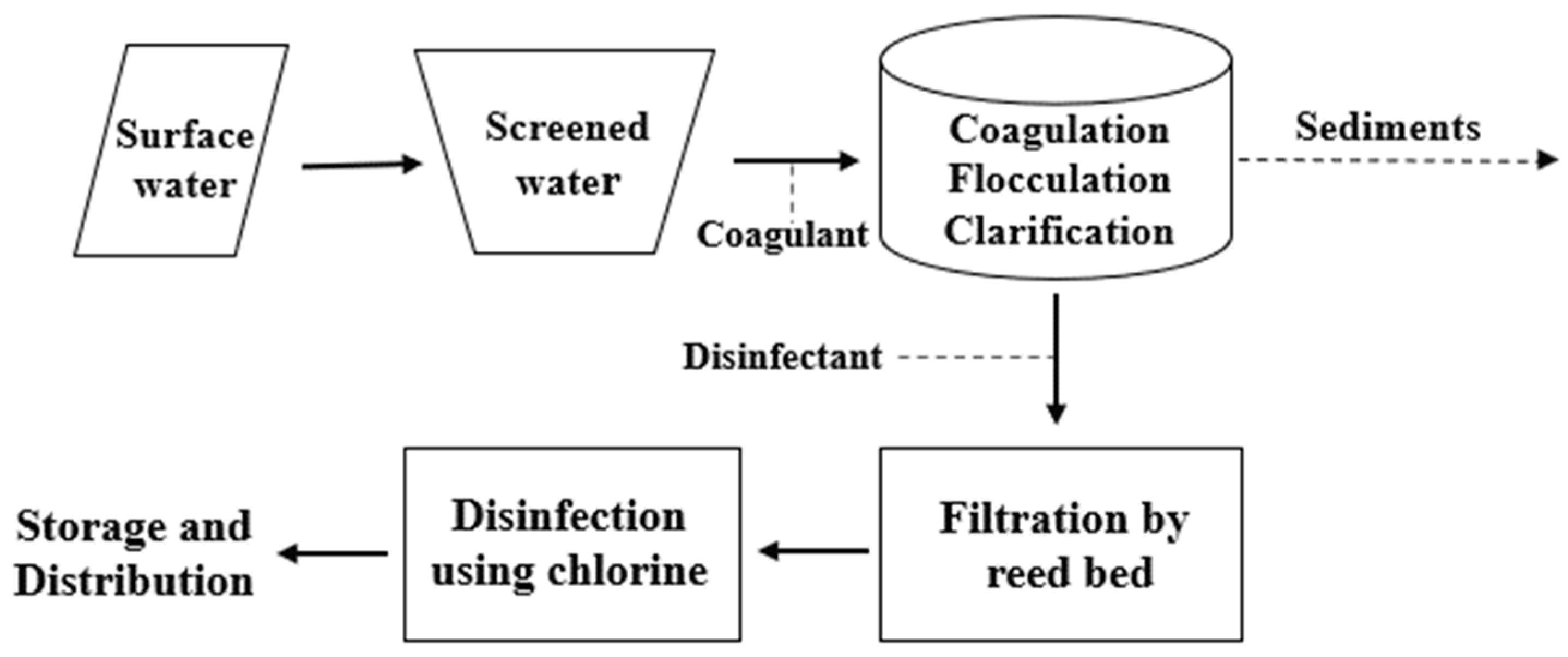
A process flow diagram for the DWTP is shown in Figure 1. The solid arrows denote the sequential advancement of water treatment, the dashed lines indicate the locations for chemical injection, and the dotted arrows represent the discharge of sediments. The surface water was extracted from rivers or lakes and then screened to remove large solids, rags, and debris of 6 mm or larger. This water is pumped and channeled to the drinking water reduction plant through an inlet pipe leading to a tank. During this stage, a coagulant is added to the water. Therefore, the tank is used in order to carry out the following processes: coagulation, in which chemicals are introduced to the water to initiate the formation of gelatinous hydracids through the attraction of particles together; flocculation, where chemicals are gradually mixed with the water to facilitate the aggregation of small suspended solids and the formation of flocs; and clarification, which reduces the solid load and removes approximately 85% to 95% of suspended solids and colloidal matter by controlling the speed of the propeller and introducing the necessary coagulants. Subsequently, a reed bed system replaces the filtration unit, with water passing through a porous medium that removes the remaining suspended solids, color, taste, odor, iron, manganese, and up to 90% of bacteria, creating a nature-based solution. Depending on the intended application of the water, an optional disinfection tank may be situated downstream before the water is either stored in a separate tank or distributed directly.
2.2. Conceptual Design
The compact unit will operate at a flowrate is equal to 2 L/s. This process can serve up to 800 persons by scaling the model and adjusting it. The current study focused on sizing an eco-friendly concept of DWTP by designing the various unit processes involved. This section includes the conceptual design for all stages of the DWTP.
2.2.1. Inlet Pipe Design
Referring to Table 1, and taking the water velocity in the inlet pipe equal to 1 m/s, the required area of a PVC circular inlet pipe is determined by dividing the flowrate by the fluid velocity, therefore the diameter of the inlet pipe should be equal to 50 mm.
2.2.2. Coagulant Tank Design
Generally, to determine the quantity of the required coagulant “Alum” for this process, a jar test must be conducted to know the water quality. A minimum alum dosage of 25 mg/L is used in our design [20], with a density of 1340 kg/m3 and a velocity of 0.8 m/s. The alum coagulant is active at 100% and its commercial strength is 50%. To determine the required volume of the alum (Equation (1)), the required mass should be divided by the density of the fluid. Therefore, using Equations (2) and (4), the required volume of alum must be 0.006 m3/day. Taking a depth of the alum tank equal to 25 cm, the proposed alum tank dimension used in this conceptual design is 20 cm × 15 cm × 25 cm.
where Valum is the required volume of alum (m3/day), Mr,alum is the required mass of alum (kg/day), is the alum density (kg/), CS is the commercial strength (%), C is the alum dosage (kg/m3), and Q is the flowrate (m3/day).
2.2.3. Circular Tank Design
Since the circular tank is dedicated to include three processes as mentioned before: coagulation, flocculation, and clarification, therefore its volume is determined by the largest volume required among them.
- For rapid mixing during coagulation, the detention time should be 10 < DT < 60 s [18]. Taking DT = 20 s, the required volume will be 0.04 m3 based on Equation (4).where V is the circular tank volume (m3), Qavg is the average flowrate (m3/s), and DT is the detention time (s).
- For the clariflocculation, the detention time should be between 2 and 4 h. Assuming that the time it takes to complete the flocculation and clarification respectively, is 30 and 150 min [18], therefore the total detention time in this phase is 180 min. Using Equation (4), the required volume will be 21.6 m3.
The governed value that determines the required volume of the circular tank is 21.6 m3. Assuming a depth of 2 m, the calculated diameter will be 3.71 m. Therefore, a diameter of 4 m for the circular tank is used in the DWTP design.
2.2.4. Propeller Design
During the coagulation, a static rapid mixer is used in order to ensure a uniform dispersion of the coagulant throughout the basin. After coagulation, the flocculation pro-cess assists in the formation of flocs, which involves slow mixing to enhance the contact between the coagulant and the feed water and for the subsequent formation of flocs. For both processes, a propeller mixer is used which is placed at 1/3 of the tank depth; at 0.65 m from its bottom.
The velocity gradient (G) remains a significant parameter for the design of the mixer. The equation to compute the G value [21] is as follows:
where G is root-mean-square velocity gradient (m/s/m), P is the power imparted to water (N.m/s), V is the mixer volume (m3), and µ is the dynamic viscosity (N.s/m2).
Using the actual volume of the circular tank that has a value of 25.13 m3, a dynamic viscosity of the fluid (µ) equal to 1.0087 N.s/m2, and a specific value of G that depends on the duration of the two processes [18], the value of the power of the propeller can be determined as follow:
- For rapid mixing operating for 20 s, the rate of change of velocity should be 600 m/s/m < G < 1000 m/s/m, taking G equal to 1000 m/s/m the corresponding power of the mixer during this phase will be 25,349 W.
- For flocculation operation for 30 min, the velocity gradient will be taken 50 m/s/m then the propeller power will be 64 W.
Hence the propeller will operate at a power of 25,349 W for 20 s during the rapid mixing phase, then operates at a power of 64 W for 30 min to form the flocs needed during the flocculation after which it stops for two and a half hours during the sedimentation to let the flocs deposit and quit through a sludge pipe, then restarts its cycle again.
In order to determine the mixer diameter, Table 2 can be used. Having a radial flow, the corresponding range is 0.14–0.5. For a tank diameter (T) of 4 m, and taking D/T equal to 0.25, the required impeller diameter (D) will be 1 m.
2.2.5. Sludge Removal Pipe Design
Assuming that the sludge will accumulate during the flocculation in the last 10 cm of the tank, the volume of the deposits and its corresponding flowrate will be respectively 1.26 m3 and 0.7 L/s. The velocity in the pipe should be between 1.2 and 1.8 m/s. Taking a velocity of 1.5 m/s, the PVC pipe diameter should be equal to 25 mm.
The sludge should be treated first and then disposed of; the treatment process is as follows: Sludge Pasteurization, Mesophilic Anaerobic Digestion, Thermophilic Aerobic Digestion, Composting (Windrows or Aerated Piles), Lime Stabilization of Liquid Sludge, Liquid Storage, Dewatering and Storage. According to the Waste Framework Directive, the sludge could undergo preparation for reuse, recycling, disposal, or other recovery processes. From these, two groups of disposal methods can be derived: organic recycling and energy and material recycling.
2.2.6. Filtration
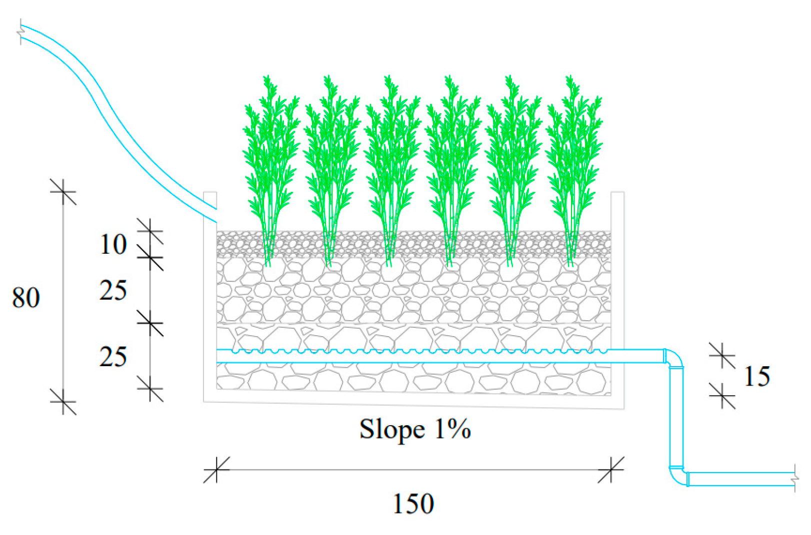
For the filtration unit, the filtration rate should be between 5 and 7 m/h. Assuming its value equal to 7 m/h, the required area of the filtration system should be 1.03 m2. Taking a length of 1 m, a width of 1.5 m and a depth of 0.8 m for the filtration system, the real volume of the reed bed system will be 1.2 m3.
The filtration unit will include three layers:
- Bottom layer: made of gravel of size 25 to 40 mm with a 25 cm thickness.
- Middle layer: made of gravel of size 10 to 25 mm with a 25 cm thickness.
- Top layer: made of silty sand with a 10 cm thickness.
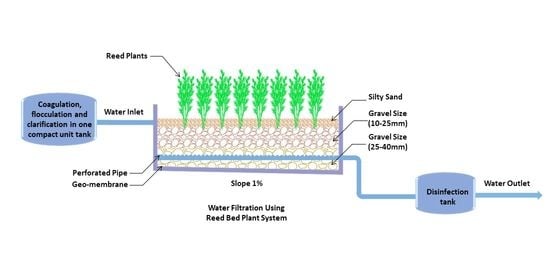
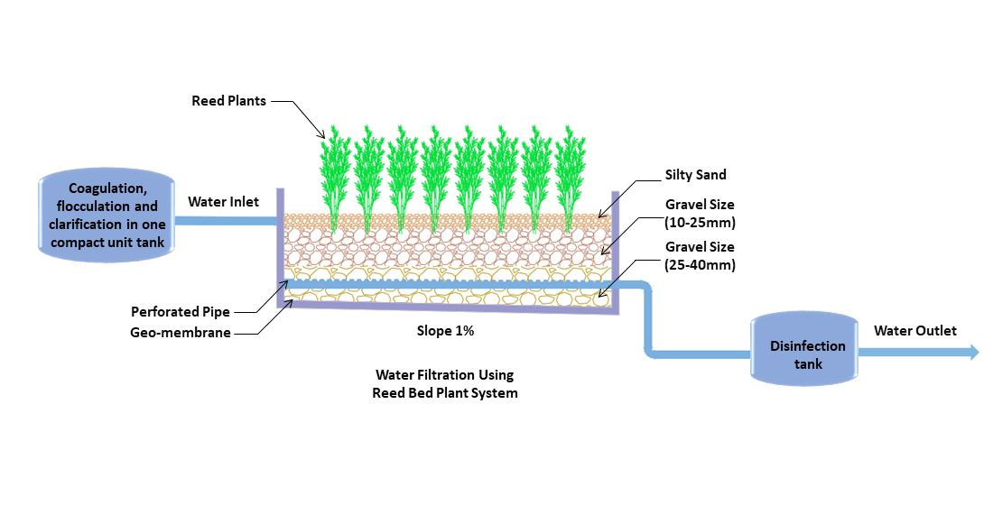
On top of all the layers, a reed bed is planted as shown in Figure 2 to ensure the consumption of organic matter in water by the bacteria present in the roots of the plants [22]. Finally, a PVC perforated pipe is placed above the bottom ground by 15 cm to let the drainage occur and collect the clean water. To build a prototype a sieve analysis test is conducted to place the three different layers, followed by the plantation of the reeds which requires six to eight months to fully grow and give the desired outcome. The species of reeds used include Phragmites australis and Typha latifolia with a density of 4 to 8 plants per m2. They have long, thin stems that can grow up to several meters in height. Their roots are shallow and spread out, allowing the reeds to grow in wet soils.
2.2.7. Disinfection
For the DWTP, filtered water is disinfected using sodium hypochlorite (NaClO), which is a chemical compound that contains chlorine. The chlorination design is achieved using the design criteria provided by [23]. Taking a chlorine dosage of 50 mg/L, its consumed mass will be 8.64 kg/day. Referring to the chlorine institute, the density of chlorine in its liquid state at a temperature of 15.6 °C is 1422 kg/m3, then the required chlorine volume should be 0.006 m3/day. Taking a 25 cm chlorine tank depth, its required area should be 0.024 m2. Therefore, the proposed chlorine tank dimension is 20 cm × 15 cm × 25 cm.
Disinfection storage time is 30 min, this gives a stored volume of 3.6 m3. Assuming a disinfection tank depth of 1.25 m, the minimum required area should be 2.88 m2. Using 4 cylindrical tanks with the same depth, the required diameter should be 0.96 m. Therefore, in the disinfection DTWP phase, 4 cylindrical tanks with a depth of 1.25 m and a diameter of 1 m are used. To ensure that these dimensions are optimal, the detention time should be checked. The actual time is the total volume of tanks divided by the average flowrate. The calculated time is 32.7 min greater than 30 min which indicates that the disinfection tank dimensions are acceptable.
After the disinfection process, the chlorine level in water is monitored using am-perometric meters to ensure that disinfection level is safe and efficient while also avoiding the risk of secondary pollution.
3. Impact
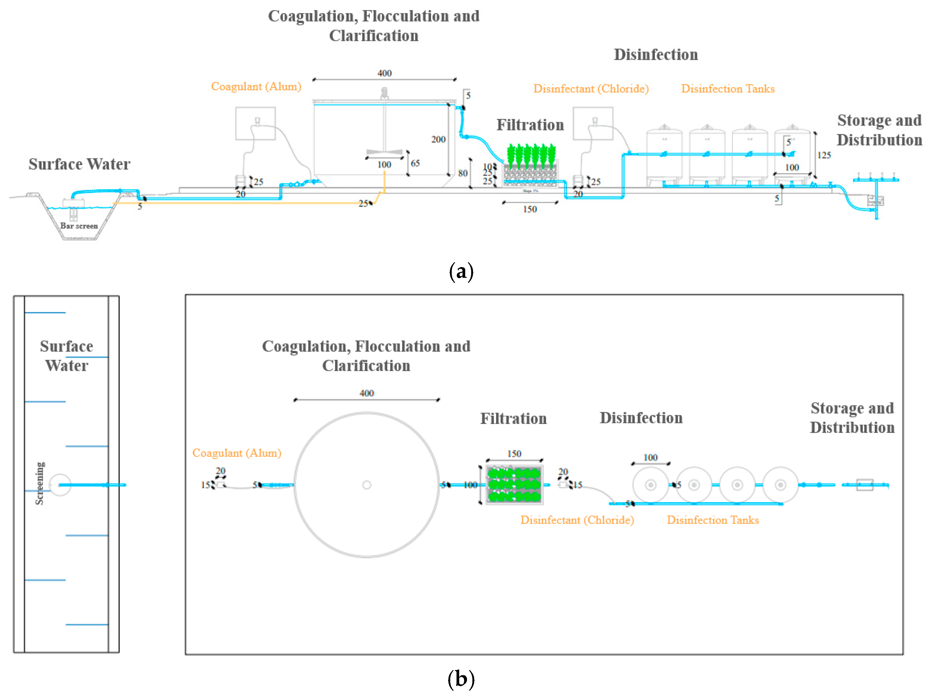
In September 2015, the United Nations (UN) adopted the Sustainable Development Goals (SDGs) aiming to significantly improve human well-being by 2030 [24]. This conceptual unit shown in Figure 3 is designed to address several SDGs in an eco-friendly way by employing recycled materials, resulting in up to a 50% reduction in cost. Its environmental and social impacts include:
- SDG number 3: “Good health and well-being”, by eliminating water borne diseases that cause serious health issues.
- SDG number 6: “Clean water and sanitation”, achieved by providing water that is palatable, odorless, and visually appealing
- SDG number 13: “Climate action”, achieved by ensuring the safe and easy disposal of used materials.
This concept optimizes the size of the unit by integrating the first three processes in a single tank, followed by a nature-integrated system that relies on reed plants to act as chemical removers of bacteria and sand layers to facilitate natural filtration processes. Additionally, this approach encourages small communities, particularly those in small villages that lack the resources to construct an entire treatment plant.
4. Conclusions
An overview of the design of the main processes for drinking water was presented in this work. Despite the availability of many filtration processes, this paper proposed a new filtration concept using a reed bed system. Fixed bed filtration is widely regarded as the most significant filtration process due to its versatility and ease of operation. Among the various types of filtration, adsorptive filtration is considered the most cost-effective technology, owing to the availability of diverse adsorbents. Reed plants, which serve as natural adsorbents, not only augment pollutant removal but also enable us to achieve the long-sought-after sustainability goals. These techniques aid in eliminating waterborne illnesses, which pose a significant threat to public health.
Author Contributions
Conceptualization, E.F.; Formal analysis, M.K., M.R. and C.A.H.; Methodology, E.F.; Software, M.K., M.R. and C.A.H.; Supervision, E.F.; Validation, E.F.; Writing—original draft, M.K., M.R. and C.A.H.; Writing—review & editing, E.F. All authors have read and agreed to the published version of the manuscript.
Funding
This research received no external funding.
Data Availability Statement
Not applicable.
Conflicts of Interest
The authors declare no conflict of interest.
References
- Ali, I. Water treatment by adsorption columns: Evaluation at ground level. Sep. Purif. Rev. 2014, 43, 175–205. [Google Scholar] [CrossRef]
- Shannon, M.A.; Bohn, P.W.; Elimelech, M.; Georgiadis, J.G.; Marinas, B.J.; Mayes, A.M. Science and technology for water purification in the coming decades. Nature 2008, 452, 301–310. [Google Scholar] [CrossRef] [PubMed]
- World Health Organization. Guidelines for Drinking-Water Quality; World Health Organization: Geneva, Switzerland, 2004; Volume 1.
- Jain, S.K.; Agarwal, P.K.; Singh, V.P.; Jain, S.K.; Agarwal, P.K.; Singh, V.P. Water quality and related aspects. Hydrol. Water Resour. India 2007, 57, 997–1033. [Google Scholar]
- Tong, Y.; McNamara, P.J.; Mayer, B.K. Adsorption of organic micropollutants onto biochar: A review of relevant kinetics, mechanisms and equilibrium. Environ. Sci. Water Res. Technol. 2019, 5, 821–838. [Google Scholar] [CrossRef]
- Noubactep, C.; Caré, S.; Crane, R. Nanoscale metallic iron for environmental remediation: Prospects and limitations. Water Air Soil Pollut. 2012, 223, 1363–1382. [Google Scholar] [CrossRef] [PubMed] [Green Version]
- Gonzalez-Perez, A.; Persson, K.M.; Lipnizki, F. Functional channel membranes for drinking water production. Water 2018, 10, 859. [Google Scholar] [CrossRef] [Green Version]
- Ali, I. New generation adsorbents for water treatment. Chem. Rev. 2012, 112, 5073–5091. [Google Scholar] [CrossRef] [PubMed]
- Chen, W.; Mo, J.; Du, X.; Zhang, Z.; Zhang, W. Biomimetic dynamic membrane for aquatic dye removal. Water Res. 2019, 151, 243–251. [Google Scholar] [CrossRef] [PubMed]
- Patel, A.; Shah, A. Sustainable solution for lake water purification in rural and urban areas. Mater. Today Proc. 2020, 32, 740–745. [Google Scholar] [CrossRef]
- Shabiimam, M.; Kazi, T.; Anas, P.; Shifa, S. Treatment of water using various filtration techniques: A review study. In Proceedings of the 3rd International Conference on Construction, Real Estate, Infrastructure and Project (CRIP) Management, Pune, India, 23–25 November 2018; pp. 229–235. [Google Scholar]
- Yang, H.; Hu, R.; Ndé-Tchoupé, A.I.; Gwenzi, W.; Ruppert, H.; Noubactep, C. Designing the next generation of Fe0-based filters for decentralized safe drinking water treatment: A conceptual framework. Processes 2020, 8, 745. [Google Scholar] [CrossRef]
- Goldstein, R.; Smith, W. Water & Sustainability (Volume 4): US Electricity Consumption for Water Supply & Treatment—The Next Half Century; Electric Power Research Institute: Washington, DC, USA, 2002. [Google Scholar]
- Bukhary, S.; Batista, J.; Ahmad, S. Design aspects, energy consumption evaluation, and offset for drinking water treatment operation. Water 2020, 12, 1772. [Google Scholar] [CrossRef]
- Bukhary, S.; Weidhaas, J.; Ansari, K.; Mahar, R.B.; Pomeroy, C.; VanDerslice, J.A.; Burian, S.; Ahmad, S. Using Distributed Solar for Treatment of Drinking Water in Developing Countries. In Proceedings of the World Environmental and Water Resources Congress 2017, Sacramento, CA, USA, 21–25 May 2017; pp. 264–276. [Google Scholar]
- Plappally, A.K.; Lienhard, J.H. Costs for water supply, treatment, end-use and reclamation. Desalination Water Treat. 2013, 51, 200–232. [Google Scholar] [CrossRef]
- Price, J.I.; Heberling, M.T.; Nietch, C.T. Economic support for decisions on source water protection. J. -Am. Water Work. Assoc. 2018, 110, 56. [Google Scholar] [CrossRef] [PubMed]
- Jagadeesh, A. Safe drinking water for all through solar disinfection. J. Rural Dev. 2010, 58, 11–13. [Google Scholar]
- American Water Works Association. Water Treatment Plant Design; McGraw-Hill Education: New York, NY, USA, 2012. [Google Scholar]
- Davis, M.L. Water and Wastewater Engineering: Design Principles and Practice; McGraw-Hill Education: New York, NY, USA, 2010. [Google Scholar]
- Hendricks, D.W. Water Treatment Unit Processes: Physical and Chemical; CRC Press: Boca Raton, FL, USA, 2018. [Google Scholar]
- Prasad, R.K.; Chatterjee, S.; Sn, D.; Sharma, S.; Vairale, M.; Veer, V. Reed Bed Plants & Their Role in Waste Water Treatment & Reclamation. In Proceedings of the National Conference on Recent Advances in Biodegradation of Human Wastes, Tezpur, India, 16–17 December 2014. [Google Scholar]
- Lee, C.; Lin, S.D. Handbook of Environmental Engineering Calculations; McGraw-Hill Education: New York, NY, USA, 2007. [Google Scholar]
- Hering, J.G.; Maag, S.; Schnoor, J.L. A call for synthesis of water research to achieve the sustainable development goals by 2030. Environ. Sci. Technol. 2016, 50, 6122–6123. [Google Scholar] [CrossRef] [PubMed] [Green Version]
Figure 1.
Process flow diagram for a proposed drinking water treatment plant.

Figure 2.
Reed bed filtration unit.

Figure 3.
(a) Side view and (b) top view of the conceptual design of DWTP (all dimensions are expressed in cm).
Figure 3.
(a) Side view and (b) top view of the conceptual design of DWTP (all dimensions are expressed in cm).


Table 1.
Intake conduit design criteria [19].
Table 1.
Intake conduit design criteria [19].
| Number of Conduits | One Minimum, Two or More Preferred |
|---|---|
| Velocity | 1.2–2.0 ft/s (46–61 cm/s) at design flow; 3–4 ft/s (90–120 cm/s) maximum |
| Type of construction | Tunnel or pipeline |
| Slope or grade | Continuous to drain or to an air release valve |
Table 2.
Tank and impeller geometries for mixing [20].
Table 2.
Tank and impeller geometries for mixing [20].
| Geometric Ratio | Range |
|---|---|
| D/T (radial) | 0.14–0.5 |
| D/T (radial) | 0.17–0.4 |
| H/D (either) | 2.0–4.0 |
| H/T (axial) | 0.34–1.6 |
| H/T (radial) | 0.28–2.0 |
| B/D (either) | 0.7–1.6 |
Disclaimer/Publisher’s Note: The statements, opinions and data contained in all publications are solely those of the individual author(s) and contributor(s) and not of MDPI and/or the editor(s). MDPI and/or the editor(s) disclaim responsibility for any injury to people or property resulting from any ideas, methods, instructions or products referred to in the content. |
© 2023 by the authors. Licensee MDPI, Basel, Switzerland. This article is an open access article distributed under the terms and conditions of the Creative Commons Attribution (CC BY) license (https://creativecommons.org/licenses/by/4.0/).
Share and Cite
MDPI and ACS Style
Farah, E.; Khalil, M.; Richa, M.; Abou Harb, C. Conceptual Design of a Compact Water Purification Unit Using Reed Bed Filtration. Separations 2023, 10, 194. https://doi.org/10.3390/separations10030194
AMA Style
Farah E, Khalil M, Richa M, Abou Harb C. Conceptual Design of a Compact Water Purification Unit Using Reed Bed Filtration. Separations. 2023; 10(3):194. https://doi.org/10.3390/separations10030194
Chicago/Turabian StyleFarah, Elias, Maria Khalil, Manuella Richa, and Chantal Abou Harb. 2023. "Conceptual Design of a Compact Water Purification Unit Using Reed Bed Filtration" Separations 10, no. 3: 194. https://doi.org/10.3390/separations10030194
Note that from the first issue of 2016, this journal uses article numbers instead of page numbers. See further details here.