
Effects of Bending of Fluidic Oscillators on Aerodynamic Performance of an Airfoil with a Flap


Department of Mechanical Engineering, Inha University, Incheon 22212, Korea
*
Author to whom correspondence should be addressed.
Processes 2021, 9(8), 1429; https://doi.org/10.3390/pr9081429
Submission received: 1 July 2021
/
Revised: 31 July 2021
/
Accepted: 16 August 2021
/
Published: 18 August 2021
(This article belongs to the Special Issue CFD Applications in Energy Engineering Research and Simulation)
Abstract
:The present work investigated the effects of bending the outlet nozzles of fluidic oscillators installed on the NACA0015 airfoil with a flap on the flow control performance and, thus, the aerodynamic performance of the airfoil. The effects of bending on fluidic oscillators have not been reported so far in previous works. The aerodynamic analysis was performed numerically using unsteady Reynolds-averaged Navier-Stokes equations. Three different cases were considered: Case 1 changes only the bending angle with a fixed pitch angle, Case 2 changes only the pitch angle without bending, and Case 3 changes both the bending and pitch angles. Although the bending of the oscillators was introduced inevitably due to a geometrical limitation in the installation, the results indicated that the bending rather improved the lift coefficient and lift-to-drag ratio of the airfoil by improving the characteristics of the fluidic oscillators, such as the jetting angle and peak velocity ratio.
1. Introduction
Flow separation that occurs on an aircraft wing negatively affects aerodynamic performance. Therefore, many studies on the control of flow separation have been conducted [1,2,3,4,5]. Flow control technologies are classified into passive flow control (PFC) [1], which attaches various structures to the surface, and active flow control (AFC) [2], which uses actuators such as plasma actuators [3], backward traveling waves [4], and periodic surface morphing [5]. AFC has an advantage of removing the drag-increase problem, which is a disadvantage of PFC, and enables effective separation control [6]. In particular, among the AFC technologies, the method using fluidic oscillators showed a superior control effect than other methods [7].
Fluidic oscillator has a simple shape and generates a vibrating jet from a steady inlet flow. Figure 1 shows the working principle of a fluidic oscillator with two feedback channels. When a constant pressure is applied to the inlet, the main stream flows along one wall of the mixing chamber by the Coanda effect. Most of the main stream proceeds to the outlet, but a part of the stream is introduced into a feedback channel to change the direction of the main stream at the inlet throat. This phenomenon is repeated to generate a vibrating jet at the outlet.
Fluidic oscillators are being investigated in recognition of their excellent performance of flow excitation in various fields such as acoustic control [8], film cooling [9], heat transfer [10], wind turbine [11], flow separation control [12,13], etc., [14,15,16,17]. Melton [14] evaluated the separation control performance under various conditions by installing fluidic oscillators on the NACA0015 airfoil equipped with a simple-hinged flap. In addition, Melton et al. [15] analyzed comparatively the flow control performance of steady jet actuators and fluidic oscillators on the airfoil and reported that the fluidic oscillators showed a similar lift increase as the steady jet actuators with a smaller flow rate. Seele et al. [16] improved the efficiency of an aircraft rudder by installing fluidic oscillators on the trailing edge of a vertical stabilizer of a commercial aircraft. Cerretelli et al. [11] applied fluidic oscillators to wind turbine blades and confirmed 10–60% lift increase. Meng et al. [17] showed that the total pressure loss coefficient decreased by 6.8% by installing fluidic oscillators on the blade suction side of a compressor cascade.
For more effective separation control using fluidic oscillators, various studies have been conducted on the installation conditions of oscillators, such as arrangement, mounting angles, mounting position, etc. Kim and Kim [18,19] conducted a study by adjusting the arrangement and mounting angles of fluidic oscillators on a hump surface and an airfoil. As a result, it was reported that the pitch angle of the oscillators had the most sensitive effect on separation control. The effect of the mounting position of the oscillators on the separation control was also investigated according to the angle of attack of the airfoil. The lift was effectively increased when the oscillators were installed downstream of the separation point, and larger drag reduction was obtained closer to the leading edge at all angles of attack. Kim and Kim [20] conducted a study by adjusting the pitch angle of fluidic oscillators to control the flow separation occurring on the flap of an airfoil using a numerical analysis, referring to the experimental model of Melton [14]. It was reported that the pitch angle of the fluidic oscillators had a greater effect on lift increase as the oscillator exits became more parallel to the flap surface.
The effects of fluidic oscillator geometry on the flow control performance have also been investigated [21,22,23,24]. Melton et al. [21] evaluated the performance of three types of fluidic oscillators with the same orifice size and reported that the fluidic oscillators with the largest jet deflection angle were the most effective for separation control. Ostermann et al. [22] investigated the pressure required to inject the same mass flow in the cases where the edge of the fluidic oscillator is straight and curved. They reported that the curved oscillator was superior in terms of energy requirement, requiring 20% less supply pressure. Jung and Kim [23] conducted a multi-objective optimization of a fluidic oscillator using unsteady Reynolds-averaged Navier-Stokes (URANS) analysis and investigated the effects of inlet nozzle width and distance between splitters on the fluidic oscillator performance.
Kim and Kim [20] applied fluidic oscillators to the flow control on an airfoil with a flap, but they adjusted the pitch angle by bending the outlets of fluidic oscillators inevitably due to the geometrical limitations of the installation for some pitch angles closer to the flap angle, where the best aerodynamic performance of the airfoil was obtained. However, the effects of the bent outlets on the performance improvement were not resolved in their work. In a following work, Kim and Kim [25] investigated how the bending angle of a fluidic oscillator outlet affects the characteristics of the fluidic oscillator with and without external flow. But, in their work, the effects of the bent outlet was evaluated only on the performance parameters of the oscillator, such as peak velocity ratio at the exit and pressure drop (not on the aerodynamic performance of an airfoil).
Therefore, the contributions of the bending angle and the pitch angle to the enhancement of aerodynamic performance confirmed in the previous study [20], have not yet been identified separately. The main purpose of the present study is to find the effects of the bending angle of fluidic oscillator outlets on the aerodynamic performance of the airfoil isolated from the effects of the pitch angle of the jet injection in the flow control of an airfoil using fluidic oscillators. This is needed to find how the bending of fluidic oscillators affects the flow control performance of the oscillators and what the best installation condition is, when they are installed on an airfoil. In this study, the fluidic oscillators were installed on a NACA0015 airfoil equipped with a simple-hinged flap, and the effects of the bending angle of the oscillator outlet and injection pitch angle on the aerodynamic performance of the airfoil were identified separately using URANS analysis.
2. Fluidic Oscillator Model, Installation Conditions and Computational Domain
The fluidic oscillator model used in this study (Figure 1) is the model with two feedback channels proposed by Melton et al. [21], which was also used by Kim and Kim [20]. An array of fluidic oscillators are installed on a NACA0015 airfoil equipped with a simple-hinged flap of 30% chord length.
Only three oscillators are included in the computational domain using periodic conditions at the sided boundaries, as shown in Figure 2. The total computational domain consists of the external flow domain of the airfoil (Figure 2a) and the internal domain of the fluidic oscillator (Figure 2b). The chord length of the airfoil was set to 305 mm, and the span length was set to 99 mm including three fluidic oscillators. The angle of attack (α) was fixed at 8°, and the flap angle (δf) was fixed at 40°. The detailed dimensions of the fluidic oscillator (Figure 2b) are shown in Table 1.
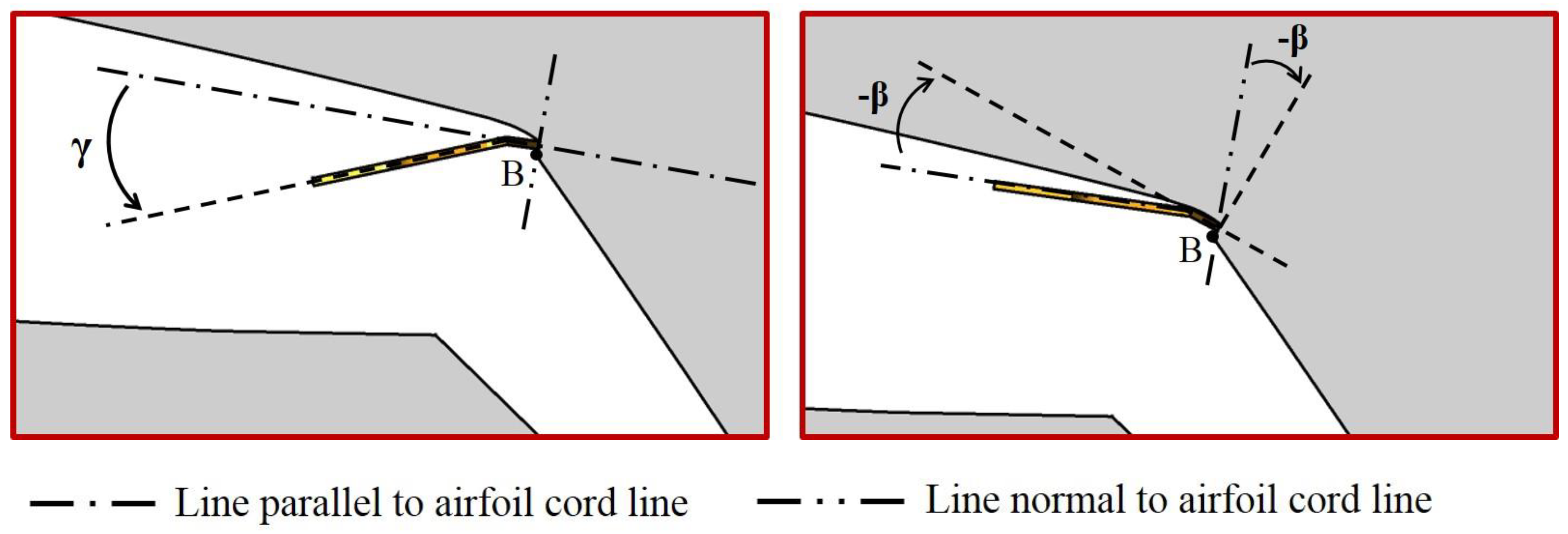
Figure 3 and Figure 4 show the installation conditions of the fluidic oscillators. The fluidic oscillator is placed at B-B’ plane as shown in Figure 3, which is located 7 mm downstream of 70% chord position from the leading edge of the airfoil. The B-B’ plane is always normal to the centerline of the oscillator outlet and, the zero pitch angle (β = 0) is defined as the condition where the oscillator outlet is mounted parallel to the chord line of the airfoil. Figure 4 shows the installation conditions of the fluidic oscillators. In this figure, the symbol γ indicates the bending angle of the outlet parts of the oscillators, and β indicates the injection pitch angle of the oscillators.
First, to investigate the effect of bending angle on the aerodynamic performance, only the bending angle of the fluidic oscillator was adjusted with the pitch angle fixed at β = 0°. The bending angle test was carried out in a range of γ = 0~40°. Next, the negative pitch angle was tested in the same range of −β = 0~40° without bending the oscillators (γ = 0°). The present study considered only the negative pitch angles, which showed good flow control performance in the previous work [20]. Actually, this test using negative pitch angles cannot be realized without bending the oscillators. However, to isolate the effect of the bending angle on the aerodynamic performance from that of the pitch angle when both the bending and pitch angles are changed with −β = γ, this unrealistic condition was considered numerically only for comparison.
3. Performance Parameters
To evaluate the aerodynamic performance of the airfoil, the lift, drag, and pressure coefficients were defined as follows:
where L, D, ρ, U, c and s indicate the lift force, drag force, fluid density, velocity, airfoil chord length and width of the computational domain, respectively. The subscript ∞ indicates free-stream value.
To evaluate the exit velocity change caused by the bending of the fluidic oscillators, peak velocity ratio of the oscillating jet at the exit of the fluidic oscillator (FVR) was defined as follows:
where the reference velocity is the velocity at the throat (width wt in Figure 2b).
is the peak value of the time-averaged jet velocity at the oscillator outlet, is the mass flow rate at the inlet, is the area of the throat, and ρ is the air density at 25 °C.
4. Numerical Analysis
In this study, three-dimensional URANS and continuity equations were solved numerically for the flow analysis using the commercial software ANSYS CFX 15.0® [26]. The shear stress transport (SST) model was used to analyze the turbulence. Pendey and Kim [27] reported that the SST model predicted the internal flow of a fluidic oscillator accurately. The SST model is known to predict flow separation in adverse pressure gradients well [28,29]. The governing differential equations were discretized using a finite-volume method. Multiple inner iterations were employed using the physical time scale for transient analysis of the flow. A high-resolution scheme of Barth and Jesperson [30] was used to discretize the advection terms and a second-order backward Euler scheme were used for the transient terms in time.
Air at 25 °C is used as the working fluid, which is assumed to be an ideal gas. For the external domain shown in Figure 2a, a uniform velocity of 25 m/s is assigned to the inlet, which corresponds to a Reynolds number of 5.0 × 10⁵ based on the chord length. A constant pressure condition of 1 atm is applied to the outlet, and no-slip boundary conditions are used at the walls. In addition, to reduce the computational time, periodic conditions are assigned to both sides of the external domain considering the periodicity of the flow, and the domain includes three fluidic oscillators following the work of Kim and Kim [20], where the optimum number of oscillators included in the computational domain was determined through a preliminary test. In the case of the internal domain shown in Figure 2b, Outlet of the domain is connected to the external domain using an interface condition. The uniform velocity condition is also used at the inlet of the oscillators. The inlet velocity can be calculated from the momentum coefficient (Cμ).
In this work, the Cμ value is fixed at Cμ = 2.64%. The momentum coefficient is defined as a ratio of total momentum flux supplied by the oscillators to the momentum flux of the external free stream as follows:
where l and n are the space between the two adjacent oscillators and the number of oscillators in the domain. The fluid density in the fluidic oscillator () is assumed to be the same as that of the external flow .
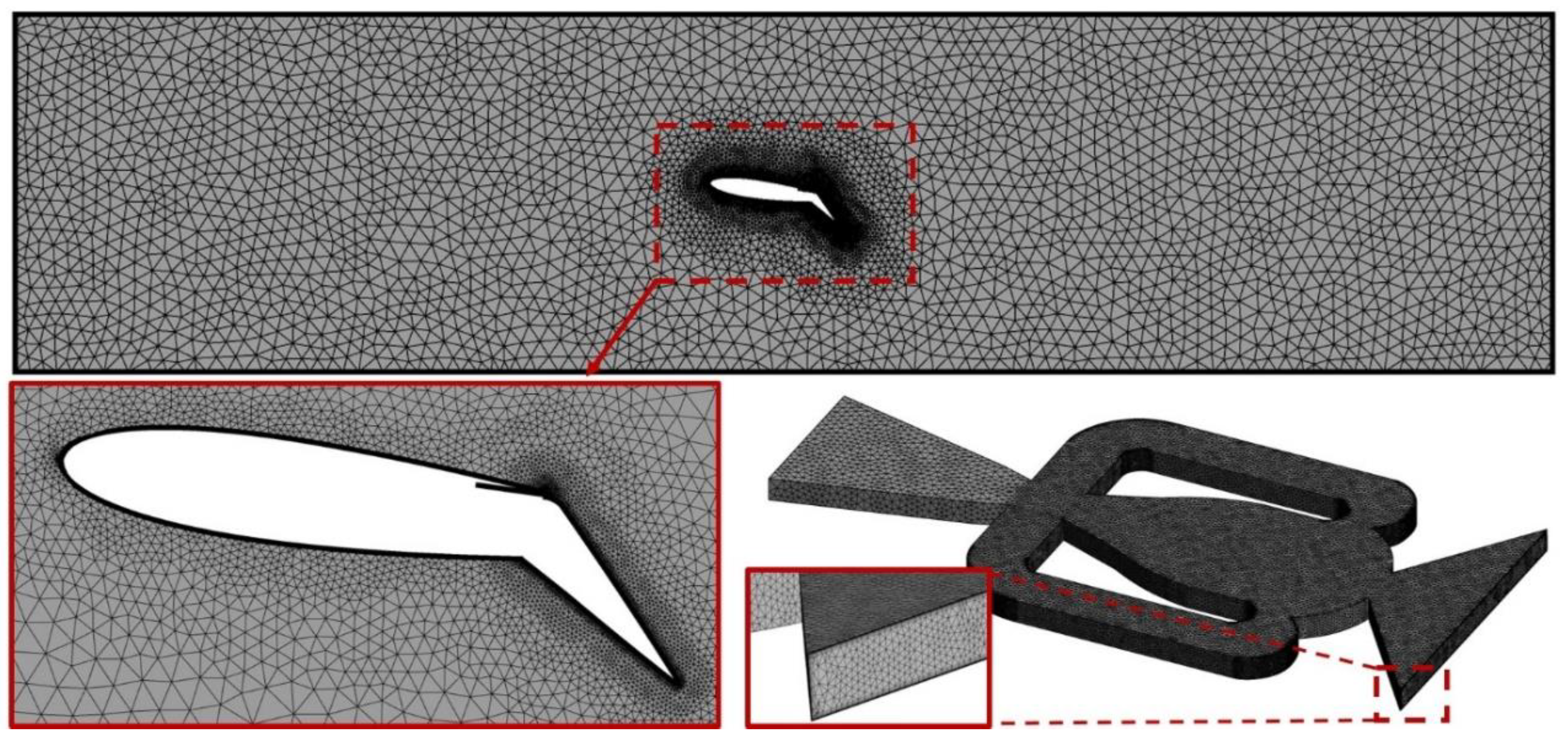
A typical grid system is shown in Figure 5. Unstructured tetrahedral meshes were created using ICEM CFD 15.0® in all domains and, to resolve the high-velocity gradients in the boundary layers, 19 and 12 prism layers were placed on the airfoil surface and the oscillator walls, respectively, with an expansion ratio of 1.2. In all cases, the first grid points on a wall surface were located at y+ < 2.
The computational results for the steady RANS analysis were used as initial values for the URANS analysis. Using the option of adaptive time step selection in ANSYS CFX 15.0®, 5 × 10⁻⁶ s was found as a time step by 2–4 repeating calculations, where the root-mean-square values of the relative residuals of the governing equations were less than 1.0 × 10⁻⁴. The calculations were performed using an Intel Xeon Phi 7250/1.4 GHz processor with 68 CPU cores. The analysis of the entire computational domain took about 48 h.
5. Results and Discussion
Because the same computational domain as in the present work was used in the previous work [20], the grid system used in the previous work was also employed in the present work. The grid system was determined in the previous work based on a grid-convergence index (GCI) analysis [31]. For an internal domain, the analysis was performed for the jet frequency of the fluidic oscillator, and the relative discretization error of the finally selected grid with 4.7 × 10⁵ cells was 0.957%. For the external domain, a grid system with 2.2 × 10⁶ cells was selected with a of 0.072%.
Numerical results were also validated in the previous work [20] using the experimental data of Melton et al. [15]. The results for the frequency of the fluidic oscillator in the calculation of the internal domain showed a relative error of about 2%, compared to the experimental measurement at a mass flow rate of 0.7 g/s, and the lift coefficient showed a relative error of 9% at α = 8° in the external flow calculation. The distributions of the pressure coefficient on the airfoil surfaces also showed reasonable agreement with the measurements.
The present study considered the three cases shown in Table 2. Case 1 is a case where only the bending angle is changed with a fixed pitch angle at β = 0, and Case 2 is a case where only the pitch angle is changed with γ = 0, and Case 3 changes both the bending and pitch angles with −β = γ, which was used to adjust the injection pitch angle in the study of Kim and Kim [22]. Thus, in Case 3, their results are introduced here without new calculations.
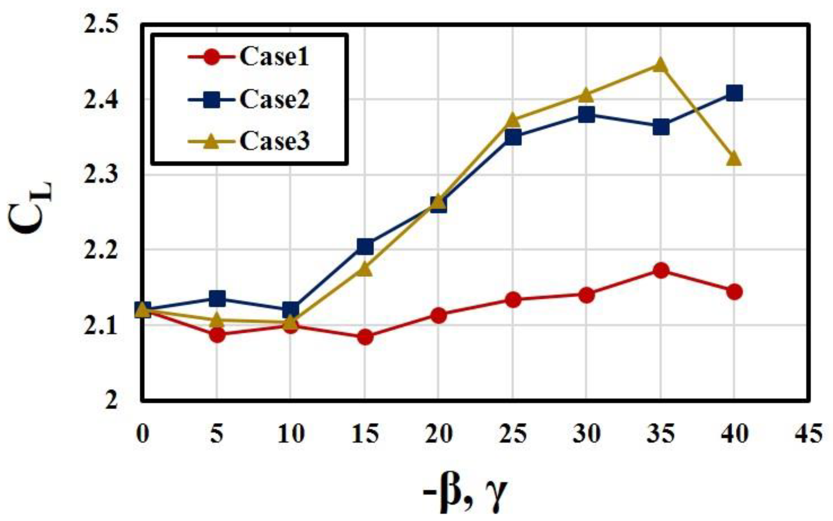
Figure 6, Figure 7 and Figure 8 show the variations of lift and drag coefficients and lift-to-drag ratio, respectively, with the bending and/or pitch angles. It is noticeable that an increase in the bending angle enhances lift coefficient without changing the pitch angle in a range of γ > 20° compared to the case with zero bending angle (Case 1). The highest CL is achieved at γ = 35° in Case 1. Kim and Kim [25] reported that, at γ = 40°, the oscillation was suppressed at low oscillator flow rates and entirely disappeared for the mass flow rates larger than 0.3 g/s in the case of a single isolated fluidic oscillator which is the same as used in the present work. In Figure 6, a sudden decrease in CL is also found at γ = 40° in Case 1 and Case 3. An increase in −β enhances CL largely for −β > 10° in Case 2 and Case 3. When γ and −β are changed together in Case 3, the interaction appears effective in improving the lift coefficient, especially at γ = −β = 35°. The differences in CL between Case 2 and Case 3 at γ = −β = 35° and 40° are obviously due to the bending angle effect shown in the results of Case 1.
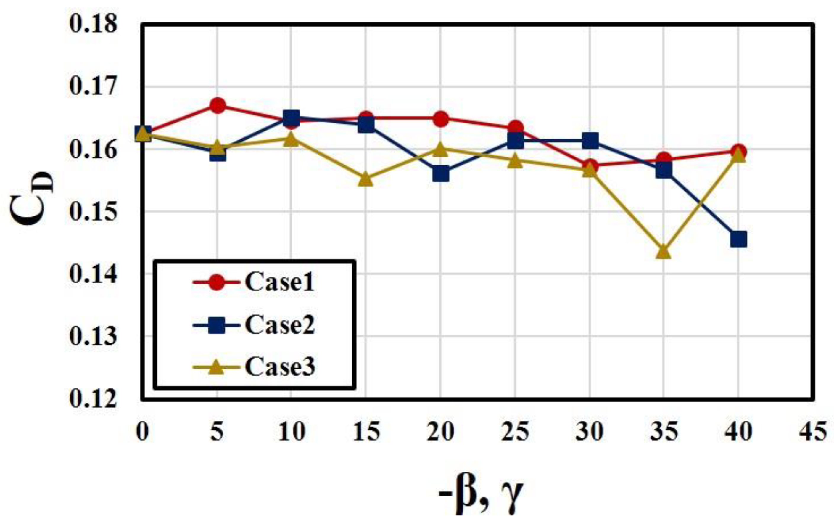
Figure 7 shows that the drag coefficient does not vary largely in all the cases except at the angles larger than 30°. The differences in CD among the cases are not large, either. It is interesting that an increase in the bending angle with β = 0° also slightly reduces CD at γ = 30–40° compared to the case without bending (Case 1). A sudden decrease in CD is found at γ = −β = 35° in Case 3, but there is no noticeable change at this angle in Case 1.
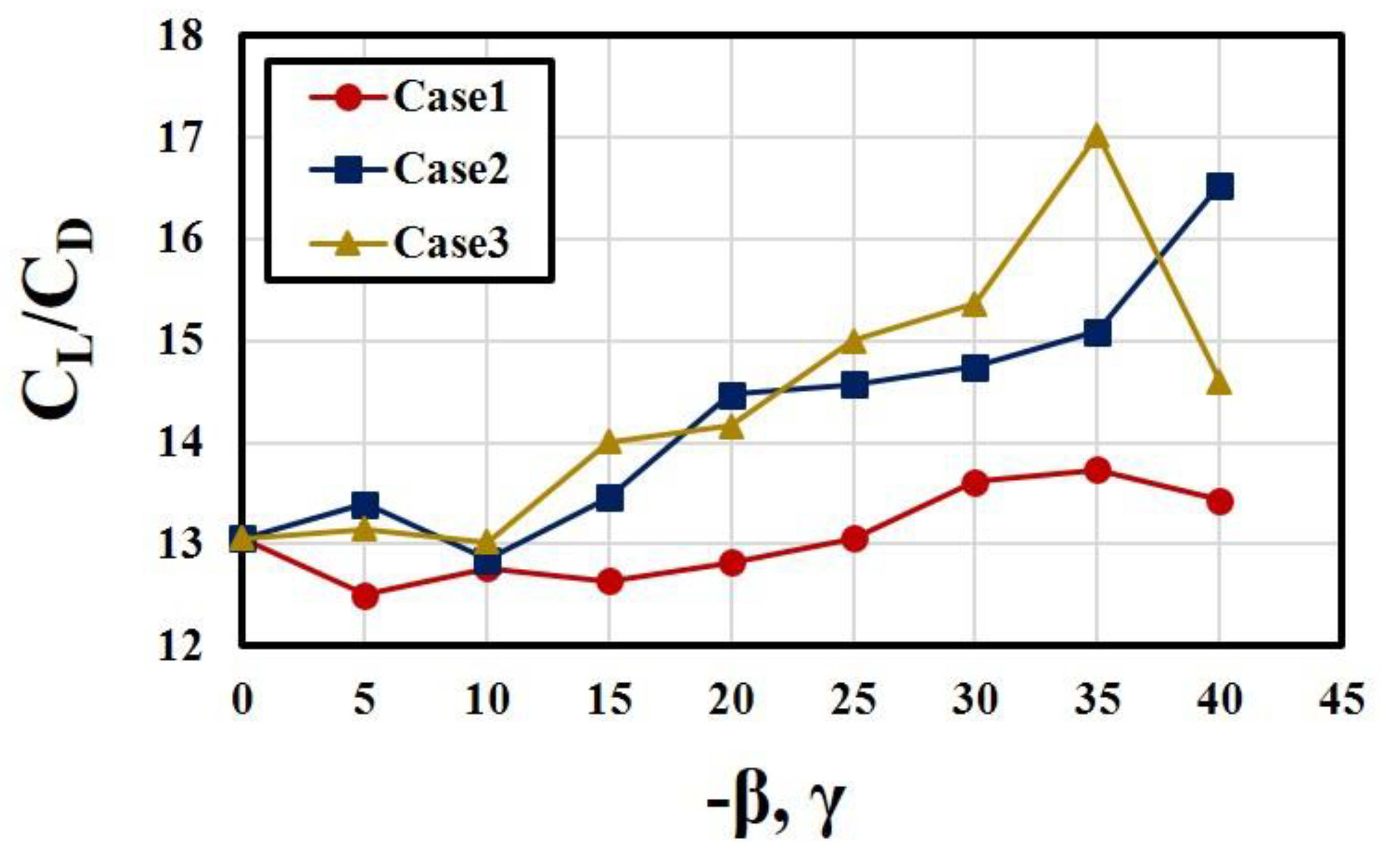
The lift-to-drag ratio is also improved by the bending of outlet nozzle in a range of 25° < γ < 40° as can be seen in Figure 8. Case 2 and Case 3 show similar variations of CL/CD with β for γ < 25°, but Case 3 shows higher values thereafter, except at −β = 40°, which reflects the coupling effect of bending and pitching angles same as in Figure 6 for CL.
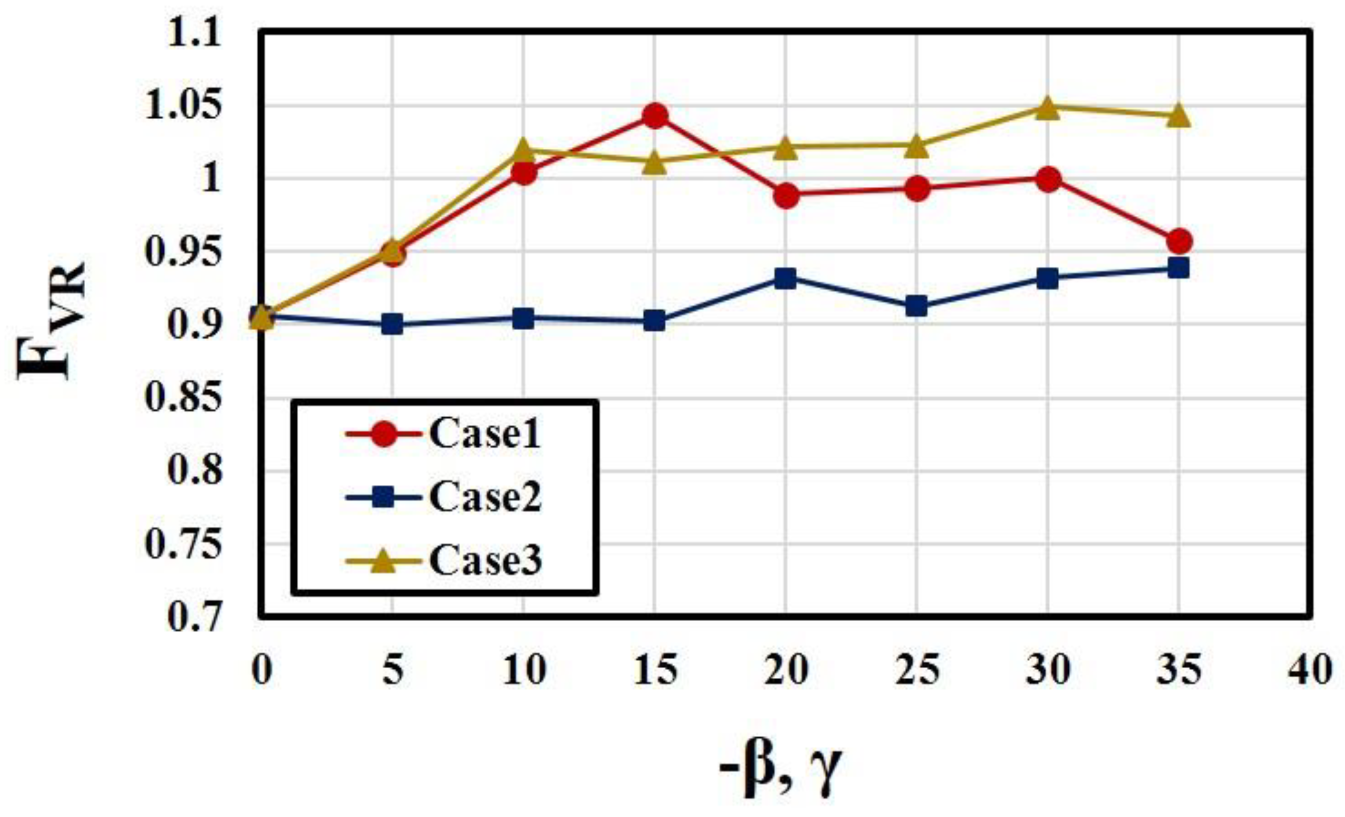
To further analyze the causes of the above results for the aerodynamic performance, changes in the characteristics of the fluidic oscillators depending on the bending and/or pitching angles are presented in Figure 9, Figure 10 and Figure 11. Figure 9 shows variations of the peak velocity ratio (FVR) with the angles in the three cases. The results show that FVR is far more affected by the bending angle (Case 1 and Case 3) than by the pitch angle (Case 2). The effect of pitch angle on FVR appears beyond −β = 15° (Case 2). However, the effect of bending angle on FVR is found over the whole tested range of γ and −β (Case 1 and Case 3). Case 3 shows higher FVR than that of Case 1 for −β > 15°, where contribution of the pitch angle to FVR is found in Case 2.
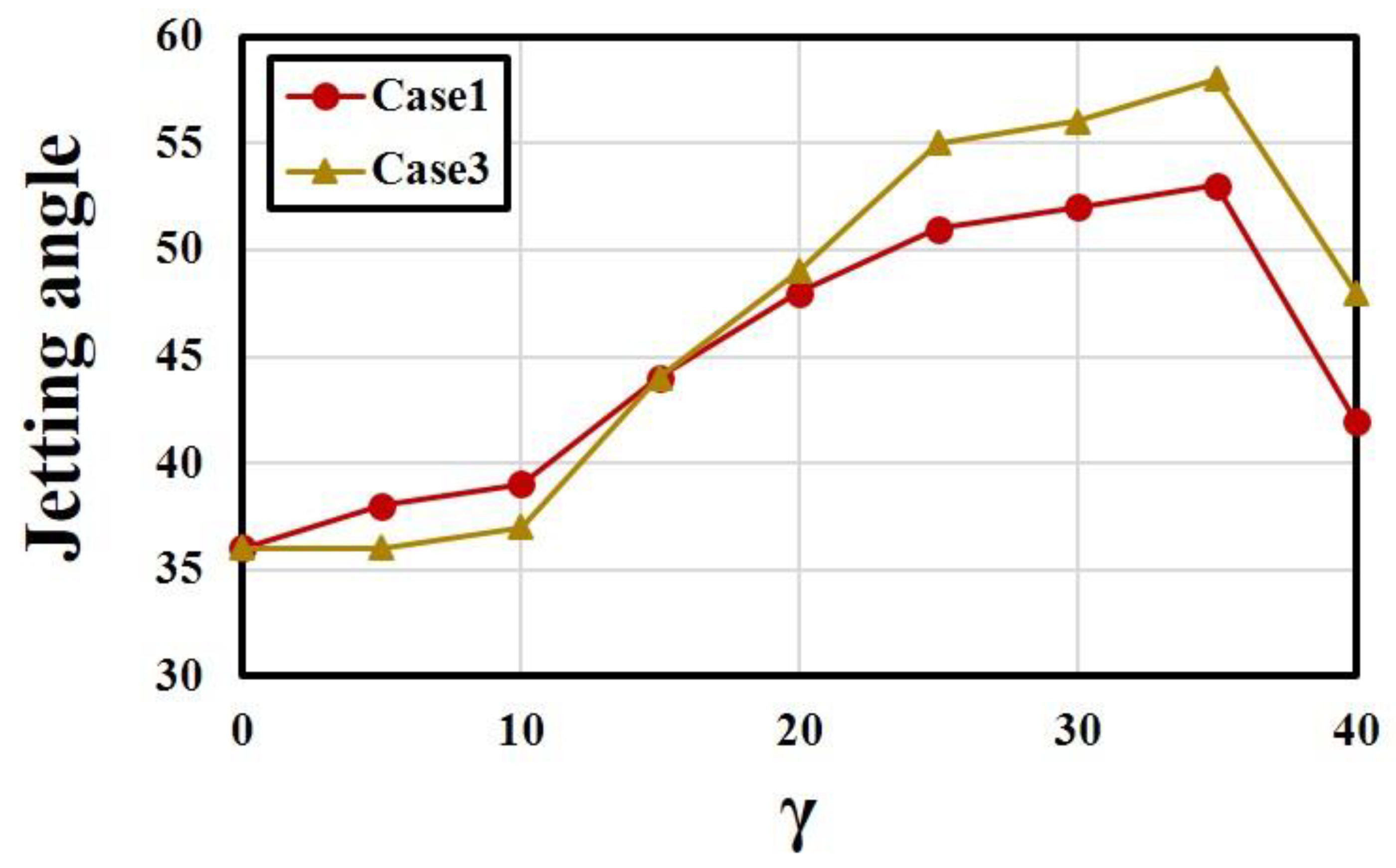
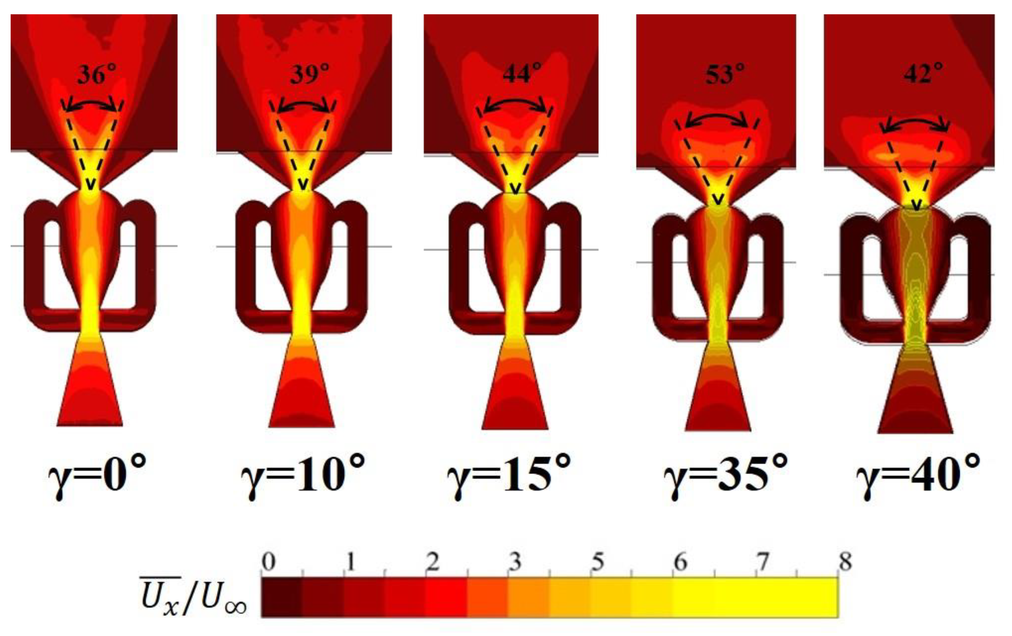
The jetting angle of fluidic oscillators is also strongly affected by the bending angle of the oscillator outlet nozzle. Figure 10 and Figure 11 show that the jetting angle increases rapidly with the bending angle and reaches the maximum at γ = 35° in both Case 1 and Case 3. In Figure 10, both curves for Case 1 and Case 3 show the similar variations, but there must be some contribution of pitch angle to the enhancement of jetting angle for γ = −β > 15° in Case 3. The sudden decrease in the jetting angle at γ = −β = 40° in Case 3 is affected strongly by the bending of the oscillators as shown in Case 1. At this angle, there must be a suppression of oscillation by the bending as reported by the previous work [27]. Therefore, the improved characteristics of the fluidic oscillators (FVR and jetting angle) shown in Figure 9 and Figure 10, especially the jetting angle, must have increased CL and thus CL/CD in Case 3 as shown in Figure 6 and Figure 8, respectively.
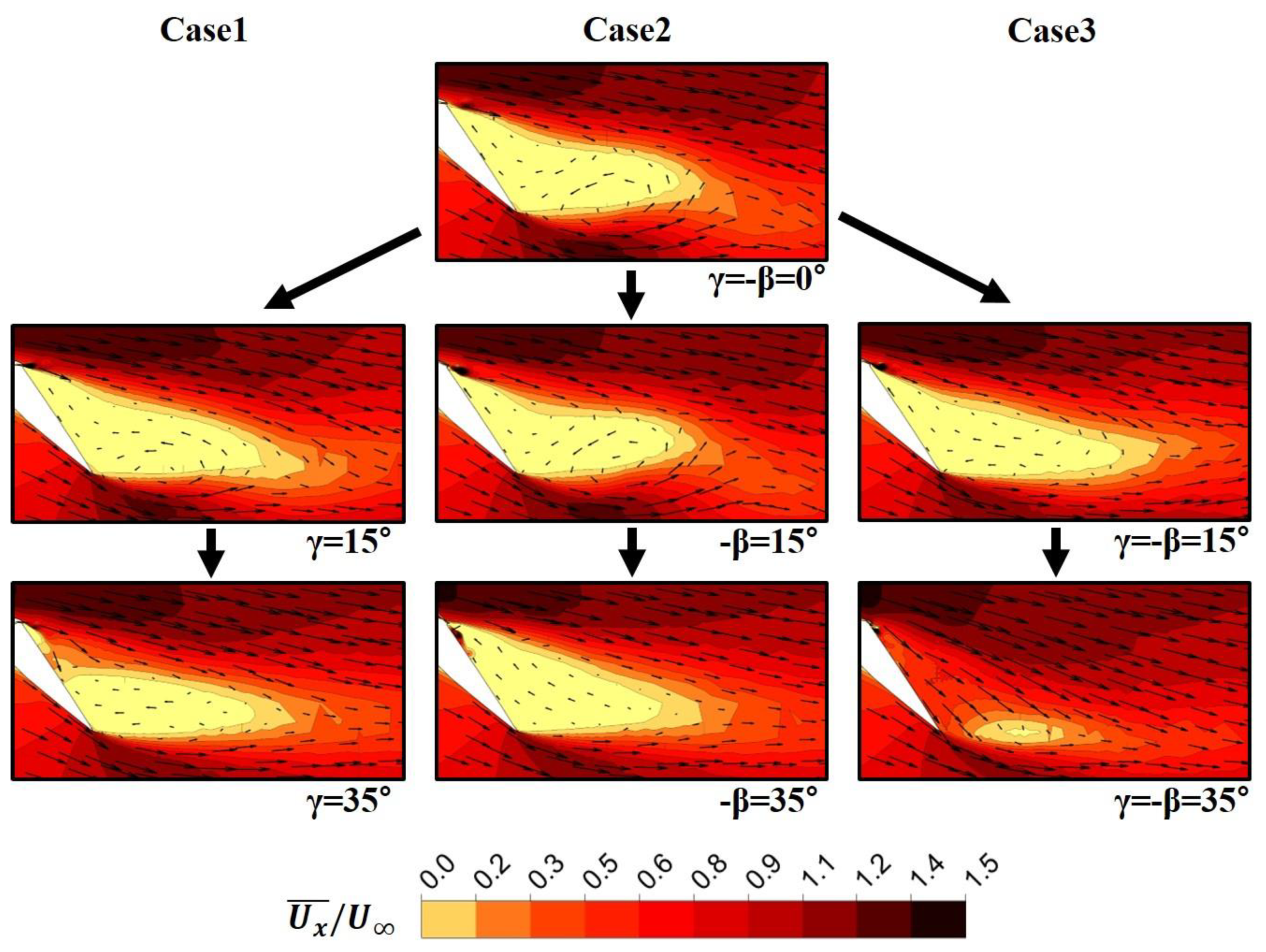
Figure 12 shows the time-averaged velocity contours in the x-z plane on the flap for different γ and/or −β at a flap angle of 40°. In Case 1, the separation area reduces as γ increases, but the pitch angle does not affect largely the separation region in Case 2. However, in Case 3, the separation region on the flap is greatly reduced as the angle increases from 15° to 35°. Therefore, it is found that the bending angle contributes to the improvement of aerodynamic performance in Case 3 by controlling the separation on the flap through changing the jetting angle and peak velocity ratio of the fluidic oscillators as shown in Figure 9 and Figure 10.
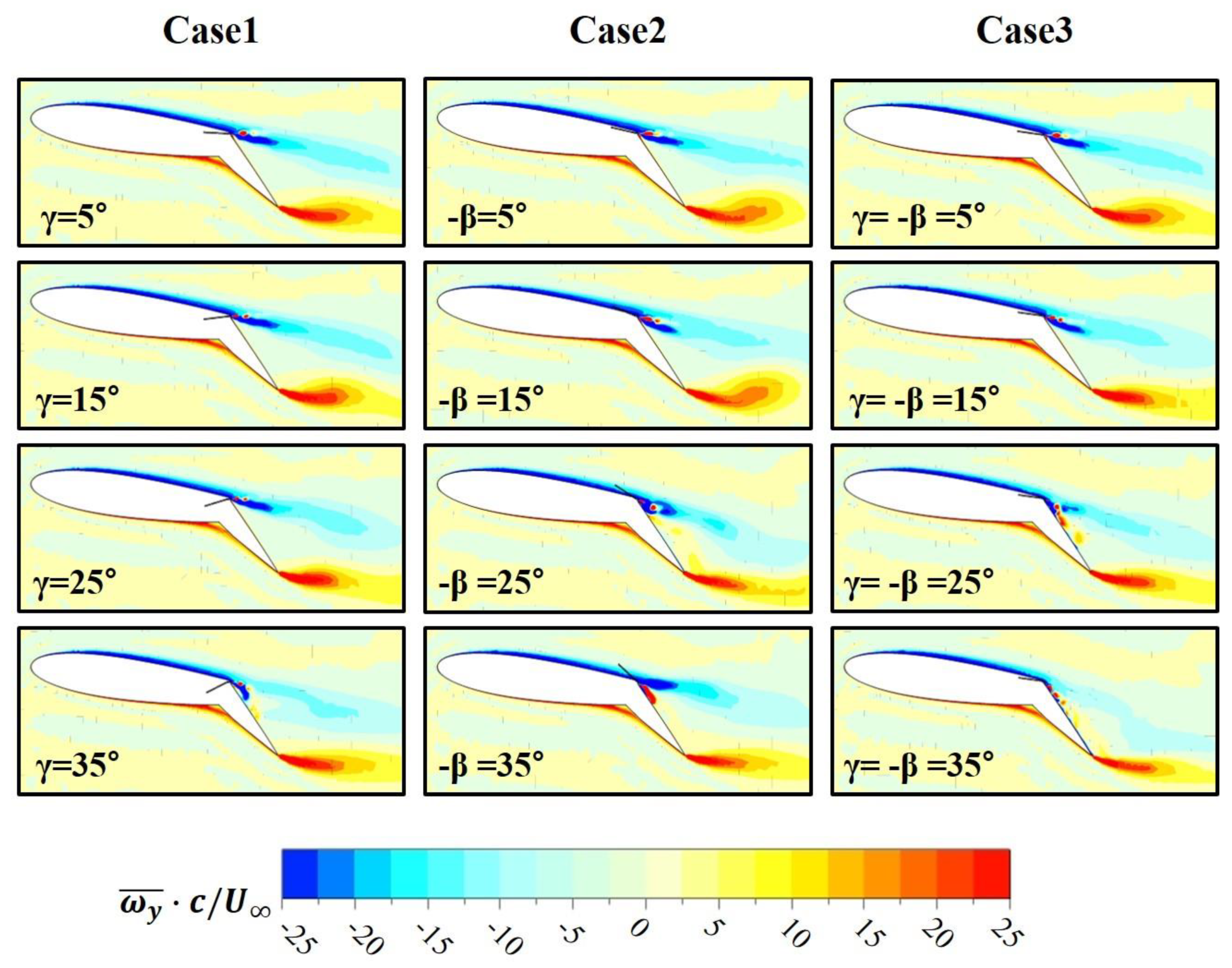
In Figure 13, time-averaged span vorticity distributions around the airfoil are compared at various angles. It is known that positive vortices generally contribute to the thrust, and negative vortices affect the lift [32]. In Case 1, at γ = 35°, the area of negative vorticity is attached to the flap surface, but this kind of attachment is not found in Case 2 with the change of β. When γ and −β are simultaneously changed in Case 3, the area of negative vorticity is attached to the flap surface at γ = 25° and 35°. This means that the coupling effect of γ and β promotes the attachment and thus enhances the aerodynamic performance.
6. Conclusions
The present work investigated the effects of bending the outlet nozzle of fluidic oscillators on the flow control performance of an airfoil with a flap using URANS analysis. Calculations were performed for two cases: the first case changed the bending angle (γ) with zero pitch angle (β) of the oscillators (Case 1), and the second case changed the pitch angle without bending the outlet nozzles (Case 2). The results of these two cases were compared to the previously reported results for the case where both the bending and pitch angles changed with −β = γ (Case 3).
It is noticeable that an increase in the bending angle enhanced the lift coefficient without changing the pitch angle in a range of γ > 20° and the highest CL was achieved at γ = 35° (Case 1). Due to the coupling with this bending effect, Case 3 showed a much higher lift coefficient at −β = 35° but a sudden drop to a lower value at −β = 40° compared to the results of Case 2. Thus, the bending was not beneficial for the lift at γ = 40°, where suppression of oscillation is expected due to excessive bending. The drag coefficient did not show large variations with the angles in all the cases, except at large angles.
Characteristics of the fluidic oscillators were also studied to find their effects on the aerodynamic performance. The peak velocity ratio at the exit of the fluidic oscillators was far more affected by the bending angle than by the pitch angle. Case 3 showed higher peak velocity ratio than that of Case 1 for −β > 15° due to the contribution of the pitch angle. The jetting angle of fluidic oscillators was found to be strongly affected by the bending angle. The jetting angle increased rapidly with the bending angle and reached the maximum at γ = 35° in both Case 1 and Case 3. The sudden decrease in the jetting angle at γ =−β = 40° in Case 3 was due to the excessive bending of the oscillators. Therefore, the improved characteristics of the fluidic oscillators, especially the jetting angle, increased the lift coefficient and the lift-to-drag ratio in Case 3, which showed the best overall performance among the tested cases.
Bending the outlet parts of the fluidic oscillators were introduced inevitably due to the geometric limitations in the installation in the previous work. However, it is interesting that the bending rather improved the aerodynamic performance of the airfoil through improving the characteristics of the fluidic oscillators, such as the jetting angle and peak velocity ratio.
Author Contributions
N.-H.K. and K.-Y.K. contributed to the overall composition and writing of the manuscript; N.-H.K. performed numerical analysis and analyzed the data; K.-Y.K. revised and finalized the manuscript. All authors have read and agreed to the published version of the manuscript.
Funding
This work was supported by the National Research Foundation of Korea (NRF) grant funded by the Korean government (MSIT) (No. 2019R1A2C1007657).
Conflicts of Interest
The authors declare there is no conflict of interest.
References
- Tang, Y.; Liu, Y.; Lu, L.; Lu, H.; Wang, M. Passive separation control with blade-end slots in a highly loaded compressor cascade. AIAA J. 2020, 58, 85–97. [Google Scholar] [CrossRef]
- Rosenblum, J.P.; Vrchota, P.; Prachar, A.; Peng, S.H.; Wallin, S.; Eliasson, P.; Iannelli, P.; Ciobaca, V.; Wild, J.; Hantrais-Gervois, J.L.; et al. Active flow separation control at the outer wing. CEAS Aeronaut. J. 2020, 11, 823–836. [Google Scholar] [CrossRef] [Green Version]
- Ebrahimi, A.; Hajipour, M. Flow separation control over an airfoil using dual excitation of DBD plasma actuators. Aerosp. Sci. Technol. 2018, 79, 658–668. [Google Scholar] [CrossRef]
- Akbarzadeh, A.M.; Borazjani, I. Controlling flow separation on a thick airfoil using backward traveling waves. AIAA J. 2020, 58, 3799–3807. [Google Scholar] [CrossRef]
- Jones, G.; Santer, M.; Debiasi, M.; Papadakis, G. Control of flow separation around an airfoil at low Reynolds numbers using periodic surface morphing. J. Fluids Struct. 2018, 76, 536–557. [Google Scholar] [CrossRef] [Green Version]
- James, P.J.; Nishi, M. Vortex generator jets-means for flow separation control. AIAA J. 1990, 28, 989–994. [Google Scholar]
- Koklu, M.; Owens, L.R. Flow separation control over a ramp using sweeping jet actuators. In Proceedings of the 7th AIAA Flow Control Conference, Atlanta, GA, USA, 16–20 June 2014. [Google Scholar] [CrossRef]
- Ganesh, R.; Surya, R. Cavity resonance suppression using miniature fluidic oscillators. AIAA J. 2004, 42. [Google Scholar] [CrossRef]
- Hossain, M.A.; Prenter, R.; Lundgreen, R.K.; Ameri, A.; Gregory, J.W.; Bons, J.P. Experimental and numerical investigation of sweeping jet film cooling. J. Turbomach. 2017, 140. [Google Scholar] [CrossRef] [Green Version]
- Wu, Y.; Yu, S.; Zuo, L. Large eddy simulation analysis of the heat transfer enhancement using self-oscillating fluidic oscillators. Int. J. Heat Mass Transf. 2019, 131, 463–471. [Google Scholar] [CrossRef]
- Cerretelli, C.; Wuerz, W.; Gharaibah, E. unsteady separation control on wind turbine blades using fluidic oscillators. AIAA J. 2010, 48, 1302–1311. [Google Scholar] [CrossRef]
- Feikema, D.; Culley, D. Computational fluid dynamic modeling of a fluidic actuator for flow control. In Proceedings of the 46th AIAA Aerospace Sciences Meeting and Exhibit, Reno, NV, USA, 7–10 January 2008; pp. 1–13. [Google Scholar]
- Seifert, A.; Greenblatt, D.; Wygnanski, I.J. Active separation control: An overview of Reynolds and Mach numbers effects. Aerosp. Sci. Technol. 2004, 8, 569–582. [Google Scholar] [CrossRef]
- Melton, L.G.P. Active flow separation control on a NACA 0015 wing using fluidic actuators. In Proceedings of the 7th AIAA Journal Flow Control Conference, Atlanta, GA, USA, 16–20 June 2014. [Google Scholar] [CrossRef]
- Melton, L.P.; Koklu, M.; Andino, M.; Lin, J.C. Active flow control via discrete sweeping and steady jets on a simple-hinged flap. AIAA J. 2018, 56, 2961–2973. [Google Scholar] [CrossRef]
- Seele, R.; Graff, E.; Lin, J.; Wygnanski, I. Performance enhancement of a vertical tail model with sweeping jet actuators. In Proceedings of the 51st AIAA Aerospace Sciences Meeting including the New Horizons Forum and Aerospace Exposition, Grapevine, TX, USA, 7–10 January 2013. [Google Scholar]
- Meng, Q.; Du, X.; Chen, S.; Wang, S. Numerical study of dual sweeping jet actuators for corner separation control in compressor cascade. J. Therm. Sci. 2021, 30, 201–209. [Google Scholar] [CrossRef]
- Kim, S.-H.; Kim, K.-Y. Effects of installation conditions of fluidic oscillators on control of flow separation. AIAA J. 2019, 57, 5208–5219. [Google Scholar] [CrossRef]
- Kim, S.-H.; Kim, K.-Y. Effects of installation location of fluidic oscillators on aerodynamic performance of an airfoil. Aerosp. Sci. Technol. 2020, 99, 105735. [Google Scholar] [CrossRef]
- Kim, N.-H.; Kim, K.-Y. Flow control using fluidic oscillators on an airfoil with a flap. Eng. Appl. Comput. Fluid Mech. 2021, 15, 377–390. [Google Scholar] [CrossRef]
- Melton, L.G.P.; Koklu, M.; Andino, M.; Lin, J.C.; Edelman, L. Sweeping jet optimization studies. In Proceedings of the 8th AIAA Flow Control Conference, Washington, DC, USA, 13–17 June 2016. [Google Scholar] [CrossRef] [Green Version]
- Ostermann, F.; Woszidlo, R.; Nayeri, C.; Paschereit, C.O. Experimental comparison between the flow field of two common fluidic oscillator designs. In Proceedings of the 53rd AIAA Aerospace Sciences Meeting, Kissimmee, FL, USA, 5–9 January 2015; Volume 10, p. 6. [Google Scholar] [CrossRef]
- Jeong, H.-S.; Kim, K.-Y. Shape optimization of a feedback-channel fluidic oscillator. Eng. Appl. Comput. Fluid Mech. 2018, 12, 169–181. [Google Scholar] [CrossRef] [Green Version]
- Pandey, R.J.; Kim, K.-Y. Numerical modeling of internal flow in a fluidic oscillator. J. Mech. Sci. Technol. 2018, 32, 1041–1048. [Google Scholar] [CrossRef]
- Kim, N.-H.; Kim, K.-Y. Effects of bent outlet on characteristics of a fluidic oscillator with and without ex-ternal flow. Energies 2021, 14, 4342. [Google Scholar] [CrossRef]
- ANSYS. ANSYS CFX-Solver Theory Guide-Release 15.0; ANSYS: Canonsburg, PA, USA, 2014. [Google Scholar]
- Pandey, R.J.; Kim, K.-Y. Comparative analysis of flow in a fluidic oscillator using large eddy simulation and unsteady Reynolds-averaged Navier–Stokes analysis. Fluid Dyn. Res. 2018, 50, 065515. [Google Scholar] [CrossRef]
- Menter, F.R. Two-equation eddy-viscosity turbulence models for engineering applications. AIAA J. 1994, 32, 1598–1605. [Google Scholar] [CrossRef] [Green Version]
- Bardina, J.; Huang, P.; Coakley, T. Turbulence modeling validation. In Proceedings of the 28th Fluid Dynamics Conference, Snowmass Village, CO, USA, 29 June–2 July 1997; American Institute of Aeronautics and Astronautics: Reston, VA, USA, 1997. [Google Scholar]
- Barth, T.; Jesperson, D. The design and application of upwind schemes on unstructured meshes. In Proceedings of the 27th Aerospace Sciences Meeting, Reno, NV, USA, 9–12 January 1989. [Google Scholar]
- Celik, I.B.; Ghia, U.; Roache, P.J.; Freitas, C.J.; Coleman, H.; Raad, P.E. Procedure for estimation and reporting of uncertainty due to discretization in CFD applications. J. Fluids Eng. 2008, 130, 0780001. [Google Scholar]
- Zha, G.; Yang, Y.; Ren, Y.; McBreen, B. Super-lift and thrusting airfoil of co-flow jet actuated by micro-compressors. In Proceedings of the 2018 Flow Control Conference, Atlanta, GA, USA, 25–29 June 2018. [Google Scholar]
Figure 1.
The mechanism of operation of a fluidic oscillator.

Figure 2.
Computational domain: (a) external domain and (b) internal domain of the oscillator.


Figure 3.
Installation location of fluidic oscillators.

Figure 4.
Installation conditions of fluidic oscillators.

Figure 5.
Grid system in internal and external domains.

Figure 6.
Variations of lift coefficient with pitch and/or bending angles of fluidic oscillators (α = 8°, δf = 40°, Cμ = 2.64%).
Figure 6.
Variations of lift coefficient with pitch and/or bending angles of fluidic oscillators (α = 8°, δf = 40°, Cμ = 2.64%).

Figure 7.
Variations of drag coefficient with pitch and/or bending angles of fluidic oscillators (α = 8°, δf = 40°, Cμ = 2.64%).
Figure 7.
Variations of drag coefficient with pitch and/or bending angles of fluidic oscillators (α = 8°, δf = 40°, Cμ = 2.64%).

Figure 8.
Variations of lift-to-drag ratio with pitch and/or bending angles of fluidic oscillators (α = 8°, δf = 40°, Cμ = 2.64%).
Figure 8.
Variations of lift-to-drag ratio with pitch and/or bending angles of fluidic oscillators (α = 8°, δf = 40°, Cμ = 2.64%).

Figure 9.
Variations of peak velocity ratio with pitch and/or bending angles of fluidic oscillators.
Figure 9.
Variations of peak velocity ratio with pitch and/or bending angles of fluidic oscillators.

Figure 10.
Variations of jetting angle with various pitch and/or bending angles of fluidic oscillators.
Figure 10.
Variations of jetting angle with various pitch and/or bending angles of fluidic oscillators.

Figure 11.
Time-averaged velocity contours and exit jetting angle (Case1).

Figure 12.
Time-averaged streamwise velocity contours and velocity vectors for different γ and/or −β angles on x-z plane at the center of computational domain (α = 8°, δf = 40°).
Figure 12.
Time-averaged streamwise velocity contours and velocity vectors for different γ and/or −β angles on x-z plane at the center of computational domain (α = 8°, δf = 40°).

Figure 13.
Time-averaged spanwise vorticity contours.


Table 1.
Geometrical parameters of the tested fluidic oscillator [20].
Table 1.
Geometrical parameters of the tested fluidic oscillator [20].
| Parameter | Value |
|---|---|
| Fluidic oscillator width, w (mm) | 14.3 |
| Inlet nozzle width, wi (mm) | 2.0 |
| Inlet chamber width, wc (mm) | 2.03 |
| Outlet throttle width, wt (mm) | 2.0 |
| Fluidic oscillator height, h (mm) | 1.0 |
| Inlet nozzle feedback channel width, (mm) | 2.41 |
| Diffuser angle of outlet nozzle, θdiff (°) | 107 |
| Distance between the inlet of mixing chamber and the throat, L (mm) | 15.6 |
Table 2.
Tested Cases.
| Change | |
|---|---|
| Case 1 | γ changed with β = 0 |
| Case 2 | β changed with fixed γ = 0 |
| Case 3 (Kim and Kim [22].) | Both β and γ changed with γ = −β |
Publisher’s Note: MDPI stays neutral with regard to jurisdictional claims in published maps and institutional affiliations. |
© 2021 by the authors. Licensee MDPI, Basel, Switzerland. This article is an open access article distributed under the terms and conditions of the Creative Commons Attribution (CC BY) license (https://creativecommons.org/licenses/by/4.0/).
Share and Cite
MDPI and ACS Style
Kim, N.-H.; Kim, K.-Y. Effects of Bending of Fluidic Oscillators on Aerodynamic Performance of an Airfoil with a Flap. Processes 2021, 9, 1429. https://doi.org/10.3390/pr9081429
AMA Style
Kim N-H, Kim K-Y. Effects of Bending of Fluidic Oscillators on Aerodynamic Performance of an Airfoil with a Flap. Processes. 2021; 9(8):1429. https://doi.org/10.3390/pr9081429
Chicago/Turabian StyleKim, Nam-Hun, and Kwang-Yong Kim. 2021. "Effects of Bending of Fluidic Oscillators on Aerodynamic Performance of an Airfoil with a Flap" Processes 9, no. 8: 1429. https://doi.org/10.3390/pr9081429
Note that from the first issue of 2016, this journal uses article numbers instead of page numbers. See further details here.