
Heat Transfer Coefficient Estimation and Performance Evaluation of Shell and Tube Heat Exchanger Using Flue Gas


1
Industrial and Systems Engineering Department, Morgan State University, 1700 East Cold Spring Lane, Baltimore, MD 21251, USA
2
Center for Advanced Energy Systems and Environmental Control Technologies, School of Engineering, Morgan State University, 1700 East Cold Spring Lane, Baltimore, MD 21251, USA
*
Author to whom correspondence should be addressed.
Processes 2021, 9(6), 939; https://doi.org/10.3390/pr9060939
Submission received: 13 May 2021
/
Revised: 20 May 2021
/
Accepted: 24 May 2021
/
Published: 26 May 2021
(This article belongs to the Special Issue CFD Applications in Energy Engineering Research and Simulation)
Abstract
:In the past few decades, water and air were commonly used as working fluid to evaluate shell and tube heat exchanger (STHE) performance. This study was undertaken to estimate heat transfer coefficients and evaluate performance in the pilot-scale twisted tube-based STHE using the flue gas from biomass co-combustion as working fluid. Theoretical calculation along with experimental results were used to calculate the specific heat of flue gas. A simplified model was then developed from the integration of two heat transfer methods to predict the overall heat transfer coefficient without tedious calculation of individual heat transfer coefficients and fouling factors. Performance including water and trailer temperature, heat load, effectiveness, and overall heat transfer coefficient were jointly investigated under variable operating conditions. Results indicated that the specific heat of flue gas from co-combustion ranging between 1.044 and 1.338 kJ/kgK while specific heat was increased by increasing flue gas temperature and decreasing excess air ratio. The developed mathematical model was validated to have relatively small errors to predict the overall heat transfer coefficient. A flue gas mass flow rate of 61.3–98.8 kg/h, a water flow rate of 13.7–14.1 L/min, and a parallel arrangement of two water-to-air heaters in an empty trailer were found to be optimal conditions for space heating purpose. In addition, a lower poultry litter feeding rate decreased heat loss of flue gas and increased heat gain of water, while a lower water flow rate also provided a lower maximum possible heat transfer rate with a higher actual heat transfer rate to quickly achieve heat equilibrium that ultimately improves the performance. This study demonstrates the possibility of collecting residual heat from the flue gas using the pilot-scale STHE system while outlining a systematic approach and process for evaluating its performance.
1. Introduction
The shell and tube heat exchanger (STHE) is a common type of exchanger apparatus widely used in several industrial processes and areas, such as chemical engineering, petroleum refining, refrigeration system, food processing, and power generation [1]. They have much lower production costs, robust geometry construction, easy cleaning and maintenance, and flexibility in their utility [1,2,3]. The STHE system mainly consists of a shell (vessel with different sizes) and a bundle of tubes inside a shell. Heat is transferred from one fluid into the other fluid, either from the tube side to the shell side through the tube walls or vice versa, to equalize the temperature. These fluids can either be liquids or gases on either the shell or tube side [4]. The type of tube plays an important role in heat transfer enhancement and can have a great effect on the overall heat transfer process. There are several types of tubes, such as plain, twisted, spiral, and longitudinally finned, that are currently used in the STHE system [4]. Compared to the round tube bundle with the same arrangement as the crossflow, Li et al. [5] found the twisted tube bundle to be better convection heat transfer. Tan et al. [6] and Tan et al. [7] investigated and compared the heat transfer performance of the twisted and smooth round tubes. Both results indicated that the twisted tube was better than the round tube in increasing the heat transfer coefficient and the efficiency of heat exchangers.
Besides supporting the tube bundles, the baffle is also responsible for maintaining desirable velocity and creating turbulence for the shell-side working fluid in conjunction with the shell and tube structure [8]. The baffle also resists vibrations to enhance fluid velocity as well as the heat transfer coefficient [2]. The type and inclination angle of the baffle are two important characteristics for influencing the overall performance [2,8]. Various types of baffles, such as segmental, double segmental, helical, disk, and doughnut type, were studied and implemented in the wider applications of STHE systems [9]. The helical baffle serves as a promising technology because of less shell-side pressure drop, better heat transfer performance, and less fluid-induced vibration. However, the helical baffle requires high capital investments to account for costs associated with manufacturing its complex shapes. In contrast, the segmental baffle has been widely adopted and remains the most used baffle in STHE systems because of its ease to fabricate with lower maintenance costs. The segmental baffle forces the shell-side working fluid to pass through in a zigzag manner, thereby improving the heat transfer with acceptable pressure drops. The inclination angle of the baffle is critical for controlling flow velocity and influencing the transfer coefficient. The inclination angle of 90 may cause a zigzag flow, resulting in a dead zone behind each baffle. This ultimately increases the fouling resistance and decreases the heat transfer rate. Zhang et al. [8] compared the performance of heat exchanger systems at inclination angles of 20, 30, 40, and 50, respectively. Results showed that the inclination angle of 40 was the best performing angle. Duan et al. [3] analyzed the flow and thermal performance of six helical baffle based STHE across three different inclination angels (20, 30, 40) and variable volumetric flow rates. The study indicated that having the inclination angle at 40 resulted in the highest heat transfer coefficient per unit pressure drop since a larger angle leads to a lower pressure drop. Based on previous findings, the segmental baffle with an inclination angle of 40 demonstrates the possibility of generating spiral flow while increasing the heat transfer coefficient.
The performance of the STHE system was evaluated in the physical experiments under several operating conditions over the past two decades. Thantharate and Zodpe [10] compared temperature changes and overall heat transfer coefficient for the twisted and plain tube based STHE under four different water flow rates to cover both turbulent and laminar flow ranges. Dubey et al. [4] tested the effectiveness of heat exchangers under variable flow conditions (e.g., 25% opening closed, 50% opening closed, and 75% opening closed) and insulation materials. Kasmir and Joshi [11] investigated the effects of mass flow rate and inlet temperature on the overall heat transfer rate. Emal and Elena [12] studied heat transfer by measuring temperature profiles and the overall heat transfer coefficient under a countercurrent and parallel flow arrangement. Abdulmumuni et al. [13] evaluated heat duty, capacity ratio, general effectiveness, the overall heat transfer coefficient, and the fouling factor under variable water flow rates. Ehyaei et al. [14] also found that extraction mass flow rate was critical to optimize heat transfer and performance of the geothermal power plant. To that end, heat transfer coefficient and its effectiveness are, respectively, two of the most important characteristics used to physically evaluate the performance of the STHE system under variable operating conditions, including water flow rates, tube type, and flow arrangement.
Specific heat of flue gas can be used to calculate enthalpy value, rate of heat flow, and the required surface, as well as overall heat transfer coefficient and the effectiveness of the STHE systems [15]. Thermal and gas properties, such as specific heat, thermal conductivity, density, and viscosity of the common working fluids (e.g., water, air), can be easily found in the thermodynamics table. However, the specific heat of flue gas during the combustion process was not available in the thermodynamic table [16]. Coskun et al. [15] estimated specific heat of flue gas for natural gas, fuel oil, and flame coal, respectively. Results indicated that specific heat ranged from 1.02 to 1.32 kJ/kgK for flame coal, 1.08 to 1.38 kJ/kgK for fuel oil, and 1.11 to 1.43 kJ/kgK for natural gas, all under variable flue gas temperature. Several similar studies investigated the effects of parameters such as the chemical composition of fuel, excess air (EA) amount, and gas temperature on the specific heat of flue gas from well-known fossil fuel combustion [15,16,17,18]. El-shafie et al. [19] estimated thermodynamic properties of flue gases from a glass furnace based on chemical composition analysis measured by the gas analyzer. There has yet to exist a formulation that can calculate the specific heat of flue gas from biomass combustion and co-combustion process, especially poultry litter and natural gas co-combustion process.
Fossil fuel depletion, environmental damages, strict regulation, and policies have collectively shifted energy production from fossil fuels toward using a variety of renewable energy resources, such as biomass. Biomass has been recognized as a major contributor to energy generation because it is abundant, cheap, sustainable, and environmentally friendly. In addition, biomass combustion has a CO2-neutral effect during the photosynthesis and combustion process for reducing greenhouse gas emissions [20,21]. Due to the inherent high moisture content and lower heating value of biomass fuels, the co-combustion of biomass and natural gas are adopted to increase combustion temperature and maintain stable combustion conditions [22]. Poultry litter is one type of biomass and animal waste from the poultry farming process [22,23]. Instead of land application of poultry litter, co-combustion of poultry litter and natural gas has been a viable alternative for producing heat and electricity [22,24]. There is the necessity of collecting heat in the hot flue gas using heat exchangers owing to the rapid development and adoption of biomass co-combustion technologies. As shown in Table 1, Qian et al. [22] found that there are various common working fluids, such as air, water, and diesel, used to test the performance of the twisted tube STHE system over the past few decades.
In more recent studies, computational fluid dynamics (CFD) and numerical simulation tools were also applied to investigate heat transfer mechanisms using the exhaust (or flue) gas, non-Newtonian, and helium as working fluid. El-Shafie et al. [19] used FORTRAN software to compare the overall heat transfer coefficient and pressure drop changes of the compact and STHE heat exchangers using exhaust gas from natural gas combustion. Davarpanah et al. [26] used FLUENT software to study heat transfer mechanism and chemical reactions during the design and simulation of ethylene dichloride thermal cracking reactor. Valizadeh et al. [27] applied CFD and performed a parametric simulation to investigate the influence of non-Newtonian fluids on different parameters, including friction coefficient, shear stress, velocity profiles, and pressure drop on spiral tubes. Wang et al. [28] numerically studied heat transfer performance of the five multi-tube heat exchangers (MTHXs) types, including smooth tubes, identical tube arrangement of transverse corrugated tubes, staggered tube arrangement of transverse corrugated tubes, identical tube arrangement of helically corrugated tubes, staggered tube arrangement of helically corrugated tubes using helium gas. There has been limited research to use flue gas from biomass co-combustion process as working fluid on heat transfer study and performance evaluation of the twisted tube based STHE system.
In the previous study, Qian et al. [29] evaluated the effect of tube shape, flow direction, and water flow rate in the lab-scale STHE system on water and trailer temperature changes using flue gas from the poultry litter and natural gas co-combustion process. As a continuation of the previous study, a pilot-scale STHE system along with the twisted tubes and 40 segmental baffles were fabricated. The main objectives of this study are to calculate the specific heat of flue gas, develop a mathematical model and estimate heat transfer coefficients, and evaluate the performance of the STHE system using flue gas from the poultry litter and natural gas co-combustion process as working fluid under various operating conditions.
2. Materials and Methods
2.1. Estimation of Coefficients, Heat Load, and Effectiveness
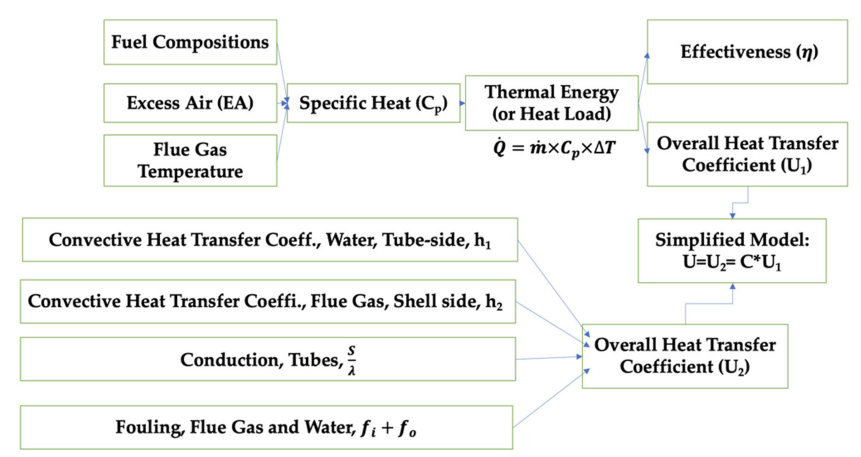
As shown in Figure 1, theoretical calculations were performed as part of the systematic approach to estimating specific heat of flue gas, heat load, effectiveness, and overall heat transfer coefficient. The specific heat of flue gas during poultry litter and natural gas co-combustion process was calculated based on fuel composition, EA, and flue gas temperature. Fuel composition was assumed to be constant because the study’s poultry litter samples were collected from one farm (Bethel Farm, Salisbury, MD, USA), which also maintains a consistent farming process (e.g., bedding materials, cleaning periods, and farming practices) [30]. Co-combustion of 5.76 kg/h poultry litter and 0.69 kg/h natural gas process was assumed to be the ideal case, whereas the complete combustion reaction for carbon, hydrogen, and sulfur in fuels with air was assumed to produce the flue gas and unburned residual products (i.e., ash). Nitrogen in poultry litter is not expected to react with oxygen because flue gas temperature during the co-combustion was less than 1000 °C. It was also generally understood that nitrogen normally reacts with oxygen over 1200 °C [31]. In addition, particulate matter (PM) emission and HCl were disregarded because they exist in relatively lower quantities. Thus, major combustion products of flue gas during the poultry litter and natural gas co-combustion are CO2, H2O, SO2, N2, and O2 [17]. Based on the chemical compositions and feeding rate of the collected poultry litter from fuel analysis and natural gas, the required oxygen amount for the complete combustion of fuels was calculated first [30,31]. Then, the required oxygen amount was divided by 0.21, and the EA ratio was multiplied in the range of 1.0 to 1.5 to calculate the required total air amount. Afterward, the total weight and weight ratio of the major components (in wt.%) in flue gas were calculated. Finally, specific heat was calculated by multiplying the weight ratio and specific heat of individual combustion products at temperatures of 0, 50, 100, 150, 200, 300, 400, 500, and 1000 , respectively. The effects of EA and flue gas temperature on the specific heat of flue gas during the co-combustion process were also investigated.
Heat transfer of the pilot-scale STHE system is determined by the heat load (or thermal energy), also known as heat flow rate, and is calculated as Equation (1):
where = heat load, in J/s; = mass flow rate, in kg/s; = specific heat, in J/g°C (or kJ/kgK); and = change in temperature, in °C. The heat load of water () on the tube side was calculated by multiplying mass flow rates of water, the specific heat of water at the average water temperature of inlet and outlet, and water temperature difference between inlet and outlet. The mass flow rate of water was derived from volumetric flow rates and density, while the specific heat of water at various water temperatures was found from the thermodynamics table [16]. The heat load of flue gas () was determined by a function of flue gas mass flow rate, calculated specific heat at average flue gas temperature of inlet and outlet, and the difference in flue temperature between the inlet and outlet of the STHE system. The mass flow rate of flue gas was assumed to be 85% of the total fuel and air amounts because ash content in poultry litter remained after the combustion process, while minor air leakage was observed due to the small holes associated with the combustion chamber’s air injection nozzles and temperature sensor holes during the physical combustion experiment.
Then, the effectiveness of the heat exchanger was calculated as Equation (2):
where = actual heat transfer rate, in J/s; = heat load of water, in J/s; = maximum possible heat transfer rate, in J/s; = minimum heat capacity rate, in J/s°C; = inlet temperature of hot fluid, in °C; = inlet temperature of cold fluid, in °C; = mass flow rate of flue gas, in g/s; = specific heat of flue gas, in J/g°C. = and because heat capacity rate of hot fluid (hot flue gas: ) is smaller than cold fluid (cold water: ).
In Equation (3), the logarithmic mean temperature difference () was determined from two temperature differences Δt1 and Δt2 at each end of the heat exchanger.
where T1 = flue gas temperature at the inlet (°C), T2 = flue gas temperature at the outlet (°C), t1 = water temperature at the inlet (°C), and t2 = water temperature at the outlet (°C). In Equation (4), the is correlated with a temperature efficiency factor () to determine the corrected effective mean temperature difference () for multi-pass heat exchangers. According to standards issued by the Tubular Exchanger Manufacturers Association (TEMA), the , , and were determined to jointly calculate the , and results showed that F = 0.95 for the pilot-scale STHE system and the was calculated as Equation (4):
Based on the calculated heat load (heat transfer rate of flue gas), , and heat exchanger area of tubes and connections (A = 1.034 m2), the overall heat transfer coefficient, , was calculated using the first method as Equation (5):
In this study, heat is transferred from flue gas into the tube wall by convection, through the tube wall by conduction, and from the tube wall to cold water again by convection. In addition, deposition of ash deposits (e.g., Na2SO4, K2SO4) via flue gas on the outer tube wall and calcium-based deposit on the inner tube wall by hard water could cause a fouling effect to increase thermal resistance and deteriorate the heat transfer rate. Thus, the second method was proposed to calculate the overall heat transfer coefficient, as Equation (6):
where convective heat transfer coefficient determined by water on the tube side (W/m2 K), convective heat transfer coefficient caused by flue gas on the shell side (W/m2 K), tube wall thickness (m), thermal conductivity of the tube material (W/m K), inner fouling factor by water (m2 K/W), outer fouling factor by flue gas (m2 K/W). Equations (7)–(9) were used to establish the convective heat transfer coefficient for both tube and shell side. First, the velocity of medium (i.e., flue gas, water) was calculated as Equation (7):
where = velocity (m/h), = mass flow rate (kg/h), = density (kg/m3), = 29.26 mm is the distance between centers of two pipes, = 15.875 mm is the outside diameter of the tube, and = 52.832 mm is the equivalent diameter for the square pitch layout of tubes. Based on the average temperature of the inlet and outlet for both flue gas and water, Reynolds number () was derived from velocity (), equivalent diameter () with kinematic viscosity (, m2/s). Herein, kinematic viscosity was also calculated by dividing dynamic viscosity (kg/m s) by density (kg/m3). Based on the calculated Re, flow conditions of the medium were determined. In the case of laminar flow ( < 2300) on the tube side, the Nusselt number on the tube side of the annular space was derived [32].
In the case of turbulent flow (Re > 10,000), the Nusselt number, Nu was derived as Equation (8):
where the exponent of the Prandtl number, is assumed to be n = 0.4 for heating of the fluid. number and thermal conductivity are derived from the thermodynamic tables [16]. Then, the convective heat transfer coefficient was calculated as Equation (9):
where = thermal conductivity (W/mK) and D = diameter (m).
The total fouling factor at the tube and shell side was assumed to be 0.0018 m2K/W because the fouling factor of biomass flue gas played such a major role while fouling of water was relatively small [16]. Conduction through copper tube wall is 4 10−6 m2 K/W where the thickness was 0.00159 m, and heat conductivity was assumed to be 385 W/m K. Results for overall heat transfer coefficient from the first and second method were compared. A correlation was found using the first six sets of overall heat transfer coefficient results. A simplified model was developed to predict the overall heat transfer coefficients. Additionally, two sets of results were used to calculate estimation error and validate the accuracy of our simplified model.
2.2. Fabrication of the Pilot-Scale STHE System
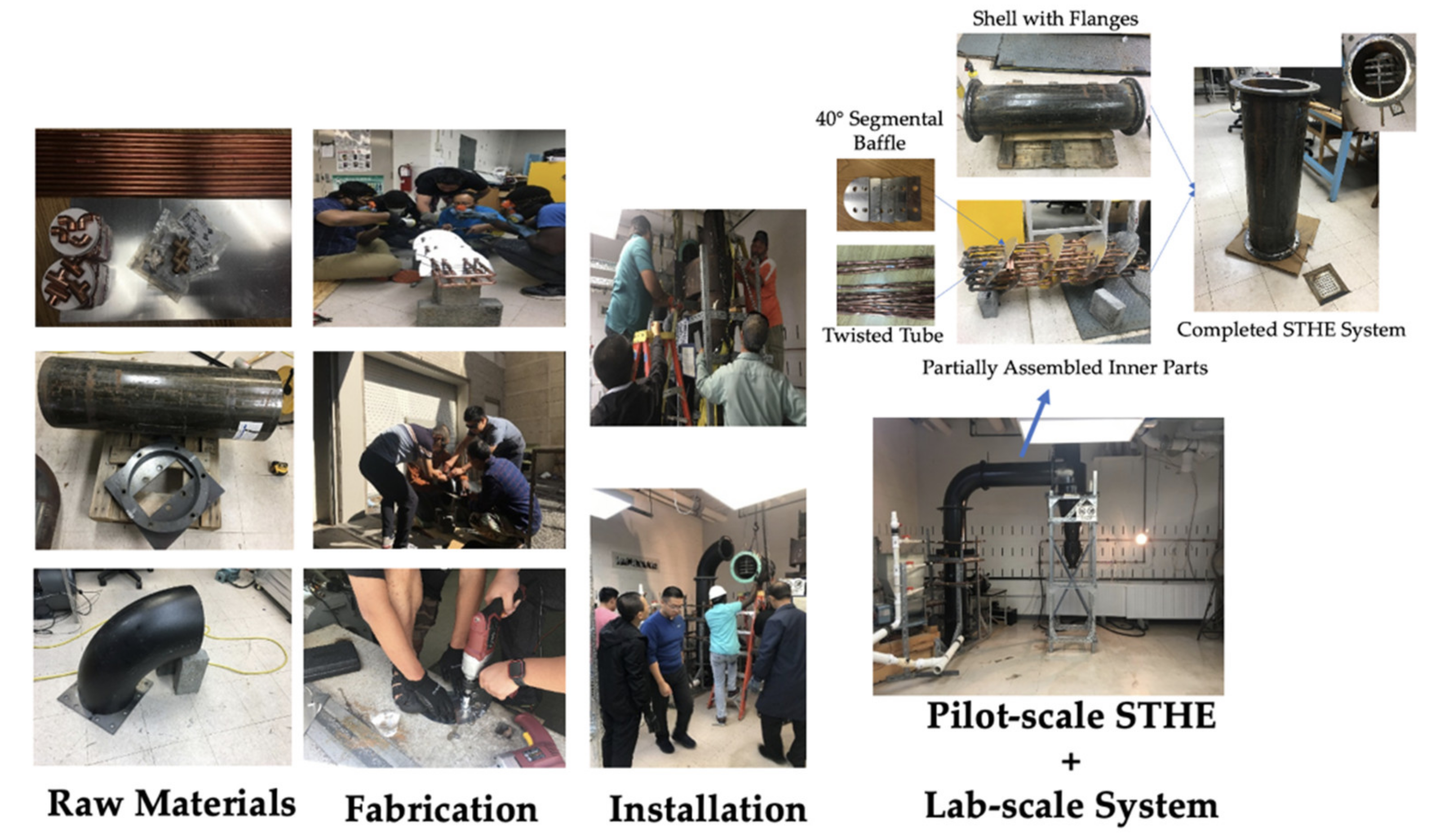
As shown in Figure 2, the pilot-scale STHE system consists of one shell, sixteen twisted tubes, and six segmental baffles.
In this study, the pilot-scale STHE system integrated the twisted tubes and 40 inclination angle of the segmental baffle to increase heat transfer coefficient and efficiency. The shell has a diameter of 304.8 mm and a length of 1016.0 mm. The tube has a diameter of 12.7 mm and a length of 863.6 mm. The segmental baffle has a diameter of 292.1 mm and a height of 206.6 mm (about 25% area cut). Raw materials for the tube section include copper type L pipes, 90 elbow connections, tees, 4-way copper cross fittings, shell material consisting of schedule 40 carbon steel pipe, and an aluminum plate for the baffle. Twisted tubes and segmental baffles were fabricated by the study’s research assistants associated with the Center for Advanced Energy Systems and Environmental Control Technologies (CAESECT) with assistance from the physical plant staff at Morgan State University. Baffle fabrication was also performed by first using a cardboard-based model to then cut the aluminum plate using a 14-gauge swivel head shear (Item 68199, Chicago Electric Power Tools, Calabasas, CA, USA), as well as bi-metal and hole saw set (Items 68,113 and 68,990, Warrior, Camarillo, CA, USA). Fabricated twisted tubes and segmental baffles were preassembled with connections for identifying compatibility between the components. After that, the soldering kit, along with a Bernzomatic Map-Pro gas cylinder and 15% phos-copper silver brazing alloy rod, was acquired to perform the hard-soldering process. Several water leakages tests and hard soldering were performed to seal all small gaps and holes until there was no water leakage in the inner parts of the pilot-scale STHE prototype without the shell. Then, two flanges were welded, and partially assembled inner parts were inserted into the shell to complete the pilot-scale STHE system. Thereafter, the pilot-scale STHE system was installed between the lab-scale swirling fluidized bed combustion (SFBC) system and cyclone system.
2.3. Experimental Setup and Evaluation of the STHE System
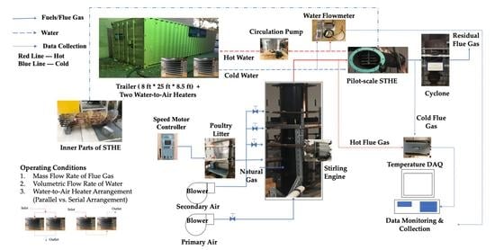
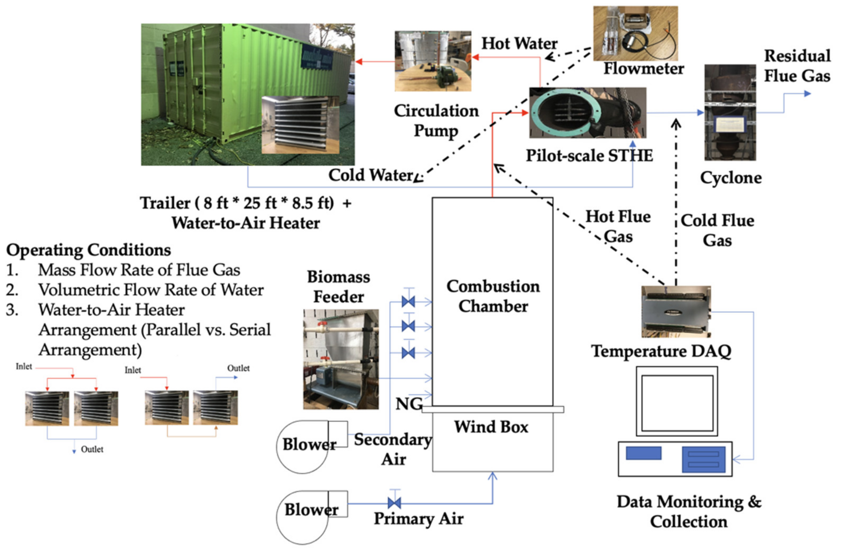
Figure 3 illustrates the experimental setup for the system analysis and performance evaluation of the pilot-scale STHE system during the poultry litter and natural gas co-combustion process. The pilot-scale STHE system was integrated with the SFBC system, two water-to-air heaters, water circulation pump, heat resistant water rubber hoses, and empty trailer (2438.4 mm width 7620.0 mm length 2590.8 mm height, Mobile Mini Storage Solutions, Middle River, MD, USA) to simulate the space heating of a typical poultry house. Natural gas was provided at a height of 120.0 mm for ignition and co-combustion with poultry litter [29,30]. Poultry litter as combustion fuel was fed into the SFBC chamber through the fuel feeder. At the same time, the primary and secondary air blowers, along with a voltage regulator, were responsible for controlling and supplying the air. In this study, hot flue gas was produced from co-combustion and used as working fluid in the shell side of the STHE system. Cold water in the twisted tube side served as another working fluid to absorb heat from the hot flue gas and generate hot water. Processed hot water from the pilot-scale STHE system was then sent to the two water-to-air heaters before rejecting heat into the cold air from an empty trailer house to provide space heating. In this study, two water-to-air heaters and the pilot-scale STHE system became a closed-loop connection with a water circulation pump and several water rubbers hoses. Heat gain was achieved from hot flue gas entering cold water by the STHE system. Heat loss was transferred from hot water into cold air using the water-to-air heaters. Insulation materials were applied to water pipes to avoid heat loss and ensure that (a) the outlet temperature of the STHE system was equivalent to the inlet temperature of the heater and (b) the outlet temperature of the heater was equivalent to the inlet temperature of the STHE system. Residual flue gas was emitted to the outside environment via the cyclone and chimney exit of the SFBC system. Vortex flow meters (SV4610, Ifm electronic company, Essen, Nordrhein-Westfalen, Germany), K-type thermocouples (Omega TJ36-CASS-18U-6, OMEGA Engineering, Norwalk, CT, USA) along with a data acquisition system (Omega OMB-DAQ-2416, OMEGA Engineering, Norwalk, CT, USA) were carefully installed to monitor water flow rate, water inlet/outlet temperature, inlet/outlet flue gas, and chamber temperatures. Trailer temperatures were calculated according to the average temperatures across three positions: window side, door side, and middle of the trailer.
Performance indicators, including temperature changes, heat load, effectiveness, CMTD, and overall heat transfer coefficient, were used to investigate and evaluate the fabricated pilot-scale STHE system under variable operating conditions, such as the mass flow rate on the tube side, mass flow rate in the shell side, and the water flow arrangement. Flue gas mass flow on the shell side is influenced by the feeding rate of poultry litter and natural gas and the amount of air being injected [29,30]. In this experiment, the mass flow rate of flue gas was determined by the feeding rate of fuels (including poultry litter and natural gas) and air. The mass flow rate of poultry litter at 5.76 and 6.81 kg/h, natural gas at 0.69 and 0.77 kg/h, and air between 66.00 and 121.00 kg/h were used to investigate the effect of flue gas mass flow rate on the shell side on the performance of the pilot-scale STHE system under constant water flow rates. Then, poultry litter and natural gas co-combustion process was conducted to reach the stable condition of SFBC chamber and STHE system for the first 90 min. Afterward, natural gas was kept at a constant 2.83 10−4 m3/s while poultry litter was fed at a rate of 5.76 kg/h from 90 to 160 min to study the effects of water flow rate on the tube side on its performance. Data collection commenced after 90 min into the co-combustion process, until 160 min in 10-min intervals. The mass flow range on the tube side was controlled by the volumetric flow rate of water at low (13.7 to 14.1 L/min), medium (14.5–14.6 L/min), and high (18.2–18.5 L/min) water flow rates, respectively. In addition, parallel and serial arrangement of the water-to-air heater in the trailer was tested to identify the effects of arrangement on the changes in water temperature and effectiveness of the pilot-scale STHE system.
3. Results and Discussion
3.1. Estimation of Specific Heat of Flue Gas during Co-Combustion Process
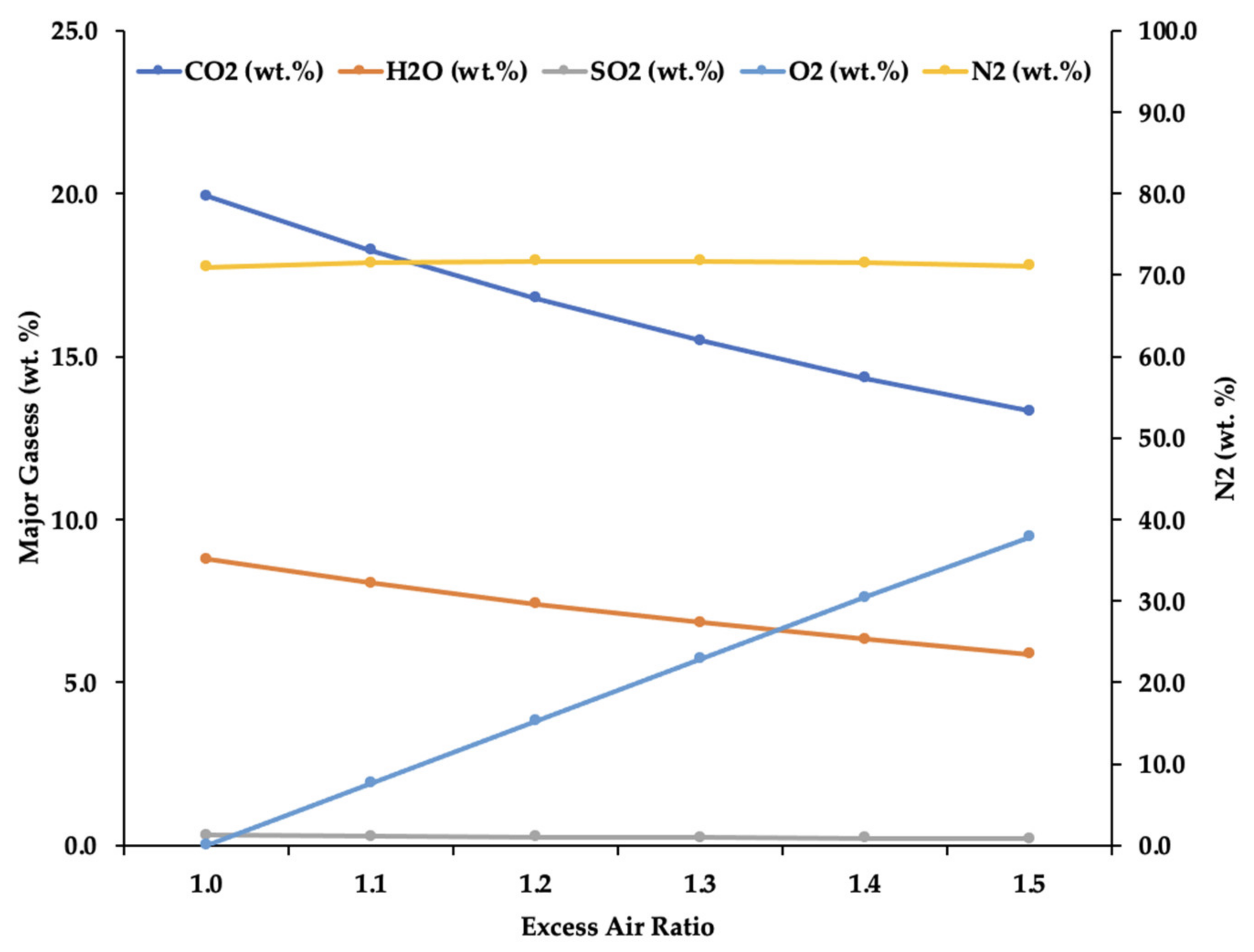
Theoretical co-combustion reaction for carbon, hydrogen, and sulfur in the poultry litter and natural gas under variable EA was calculated using the mass balance equation [15,33]. Theoretically, complete co-combustion of 5.76 kg/h of poultry litter and 0.69 kg/h of natural gas is calculated to require 34.88 kg/h to 52.33 kg/h air to achieve complete combustion and thereby produce 7.74 kg/h carbon dioxide (CO2), 3.41 kg/h water (H2O), and 0.12 kg/h sulfur dioxide (SO2) along with nitrogen (N2) in the amount of 27.56 to 41.34 kg/h and oxygen (O2) in the amount of 0 to 5.49 kg/h. Figure 4 summarizes the composition of major combustion products (in wt. %) during the co-combustion process at EA ratios between 1.0 to 1.5. The composition of H2O ranged from 5.87% to 8.79%, CO2 from 13.32% to 19.93%, and SO2 from 0.21% to 0.31%, along with unreacted 70.97 to 71.74% N2 and 0 to 9.46% O2 in the flue gas. Results showed that changes in SO2 and N2 were not obvious when EA increased from 1.0 to 1.5. However, weightings of CO2 and H2O were found to decrease while O2 weightings increased.
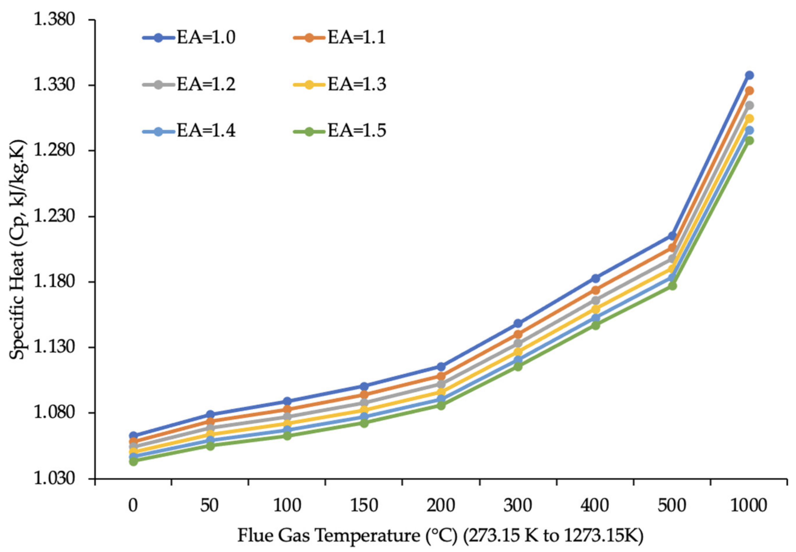
Figure 5 shows specific heat of flue gas during a poultry litter and natural gas co-combustion process range from 1.063 to 1.338 kJ/kgK, 1.058 to 1.326 kJ/kgK, 1.054 to 1.315 kJ/kgK, 1.051 to 1.305 kJ/kgK, 1.047 to 1.296 kJ/kgK, and 1.044 to 1.288 kJ/kgK for EA ratios of 1.0, 1.1, 1.2, 1.3, 1.4, and 1.5, respectively under constant flue gas temperature. It was found that the specific heat of flue gas during the co-combustion process of poultry litter and natural gas decreased with increasing EA ratios. Coskun et al. [15] also investigated the effects of EA ratio between 1.0 to 2.5 on the specific heat of flue gas during the combustion process of fossil fuels, including natural gas, fuel oil, and flame coal. Both studies observed that the specific heat of flue gas decreased when EA was increased across different types of fuel. Combined with the observation from Figure 4, increasing EA decreased the composition of H2O and CO2 while the percentage of O2 increased, resulting in lower specific heat values. This is because both H2O and CO2 have a higher specific heat than O2 [16]. On the contrary, it was found that the specific heat of flue gas during the poultry litter co-combustion process increased by increasing flue gas temperature from 0 to 1000 °C (equivalent to 273.15 to 1273.15 K) at constant EA ratios. As the flue gas reaches higher temperatures, vibrational and kinetic energy also increased, thereby requiring more thermal energy, and ultimately raising specific heat values in the process. It was not surprising that the effect of flue gas temperature and EA on specific heat were inversely related because EA lowers combustion efficiency and flame temperature during co-combustion. Many previous research studies concluded that flue gas temperature and EA had an opposite relationship during the biomass and fossil fuel combustion processes [22,34]. Moreover, it was found that specific heat of poultry litter and natural gas co-combustion had a range of 1.044 to 1.338 kJ/kgK, which is slightly smaller than the specific heat of natural gas combustion (1.11 to 1.43 kJ/kgK) due to different chemical compositions of fuels, such as lower carbon and hydrogen contents of poultry litter compared to natural gas. It was also known that specific heat of air was 1.006 kJ/kgK at 273.15 °K (0 ) and 1.184 kJ/kgK at 1,273.15 °K (1000 ) [16]. This confirmed that the specific heat of flue gas was slightly higher than the specific heat of air because of the difference in composition, whereby flue gas had a higher portion of H2O and CO2 compared to air. These results suggested that one could predict the specific heat of flue gas based on the fuel compositions, EA, and flue gas temperature.
3.2. Estimation and Comparison of Overall Heat Transfer Coefficient
In the laboratory experiment, co-combustion of 5.76 kg/h of poultry litter and 0.69 kg/h of natural gas under variable EA ratios were performed in the lab-scale SFBC chamber. Table 2 summarizes experimental results of the inlet (entering the SHTE) and outlet (exiting the STHE) flue gas temperature, inlet and outlet water temperature, mass flow rate of flue gas, and calculated specific heat of flue gas at average inlet and outlet temperatures of flue gas during the poultry litter and natural gas co-combustion process. It was found that heat load was between 31.6 to 39.1 MJ/h, CMTD was between 201.8 to 223.6 °C, and overall heat transfer coefficient (U1) for the pilot-scale STHE was between 42.1 to 46.9 W/m2K using the first method (Equations (1)–(5)).
Table 3 summarizes the estimation results of the overall heat transfer coefficient (U2) using the second approach (Equations (6)–(9)). It can be observed that convective heat transfer coefficient at shell-side (hi) ranged from 42.7 to 51.0 W/m2K and is much smaller than measurements taken at the tube side (h2, close to 232 W/m2K). This is because the flue gas on the shell side had a lower thermal conductivity than the water on the tube side. It was found that the effects of conduction at the tube wall were 4.13*10−6 m2K/W, and fouling was estimated to be 0.0018 m2K/W. To that end, a combination of these effects resulted in the overall heat transfer coefficient that measured between 33.9 to 39.0 W/m2K using the second method.
The values from the second method, U2, were slightly lower than the overall heat transfer coefficient from the first method, U1 (between 42.1 and 46.9 W/m2K). Abdulmumuni et al. [13] also found that the overall heat transfer coefficient was 201.0 W/m2K when using the first method, thereby exceeding the 98.1 W/m2K heat transfer coefficient associated with using the second method. A possible reason for this difference between the two methods is that the first approach makes a rough estimation of the heat transfer area where it only considers the surface area of tubes and connections between the tubes. Other possible heat transfer areas, such as the segmental baffles and shell in the STHE system, were ignored. In addition, heat loss from the shell surface to the environment via radiation was also ignored. The second method, on the other hand, was more comprehensive and required more data, such as density, kinetic viscosity, thermal conductivity at different temperatures for flue gas and water derived from the thermodynamics tables. Therefore, the second method was widely adopted for our heat transfer studies for optimal accuracy with tedious calculations.
Based on results from the first six data sets in Table 2 and Table 3, we found that there was a correlation factor of 0.814 between U1 and U2. Therefore, this study suggests an approach that uses a simple calculation process using the first method to estimate the overall heat transfer coefficient, Uets. = 0.814U1. Absolute average error (AAE) and average bias error (ABE) were also used to evaluate the accuracy and suitability of regression model applications [35]. It was found that this simple model had lower estimation errors, ABE of 0.08% and AAE of 2.39%. The last two data sets were used to validate the results, whereby errors were measured at 3.7% and 5.6%, respectively. This confirms that this simplified model can be used to estimate the overall heat transfer coefficients for a pilot-scale STHE system during a poultry litter and natural gas co-combustion process.
3.3. Effect of Flue Gas Mass Flow Rate on the Shell Side
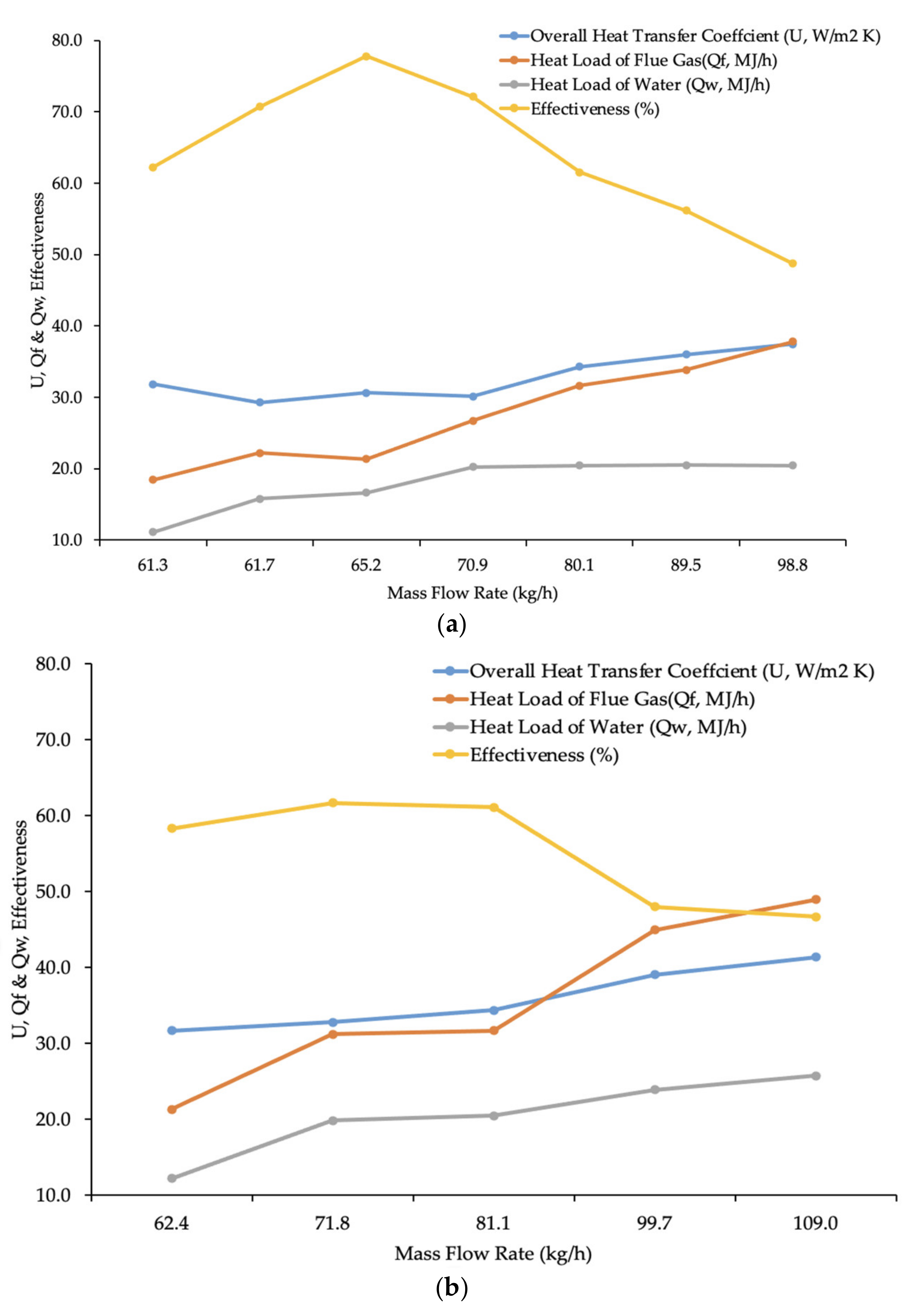
As shown in Figure 6, the overall heat transfer coefficient, heat loss of flue gas, heat gain of water increased from 31.9 to 37.5 W/m2K, 18.44 to 37.82 MJ/h, and 11.10 to 20.46 MJ/h, respectively, by increasing the mass flow of flue gas from 61.3 to 98.8 kg/h, for the case of poultry litter at 5.76 kg/h. Similar results were found when the overall heat transfer coefficient, the heat loss of flue gas, heat gain of water was increased from 21.3 to 48.9 W/m2 K, 21.27 to 48.91 MJ/h, 12.16 to 25.71 MJ/h, respectively, by increasing the mass flow of flue gas from 62.4 to 109.0 kg/h, for the case of poultry litter at 6.81 kg/h. Increments in mass flow rate of flue gas on the shell side increased fluid velocity and the Reynolds number and convective heat transfer on the shell side, which ultimately resulted in the increase in the overall heat transfer coefficient associated with the STHE system. In addition, the heat load of flue gas was increased by increasing the mass flow rate of flue gas because the increasing feeding rates of poultry litter elevated heating values of fuels while releasing more heat into the flue gas during co-combustion. As a result of heat load increments on the shell side, the heat gain of water from the tube side was also increased. It was found that effectiveness ranged between 48.7% and 77.8% for the case of poultry litter at 5.76 kg/h, while effectiveness ranged between 46.7% to 61.7% for the case of poultry litter at 6.81 kg/h. Effectiveness was slightly lower at higher poultry litter feeding rates because heat loss of flue gas increased between 2.83 to 9.99 MJ/h by increasing feeding rate while heat gain of water was relatively small (about 1.06–5.26 MJ/h) by keeping constant for the water flow rate. It also showed that similar overall heat transfer (between 30 and 40W/m2 K) with higher efficacy was achieved at a lower feeding rate of poultry litter (5.76 kg/h). These results support the use of a lower feeding rate of poultry litter at 5.76 kg/h and further investigating effect of water flow rate on the tube side on the system performance.
3.4. Effect of Water Flow Rate in Tube Side
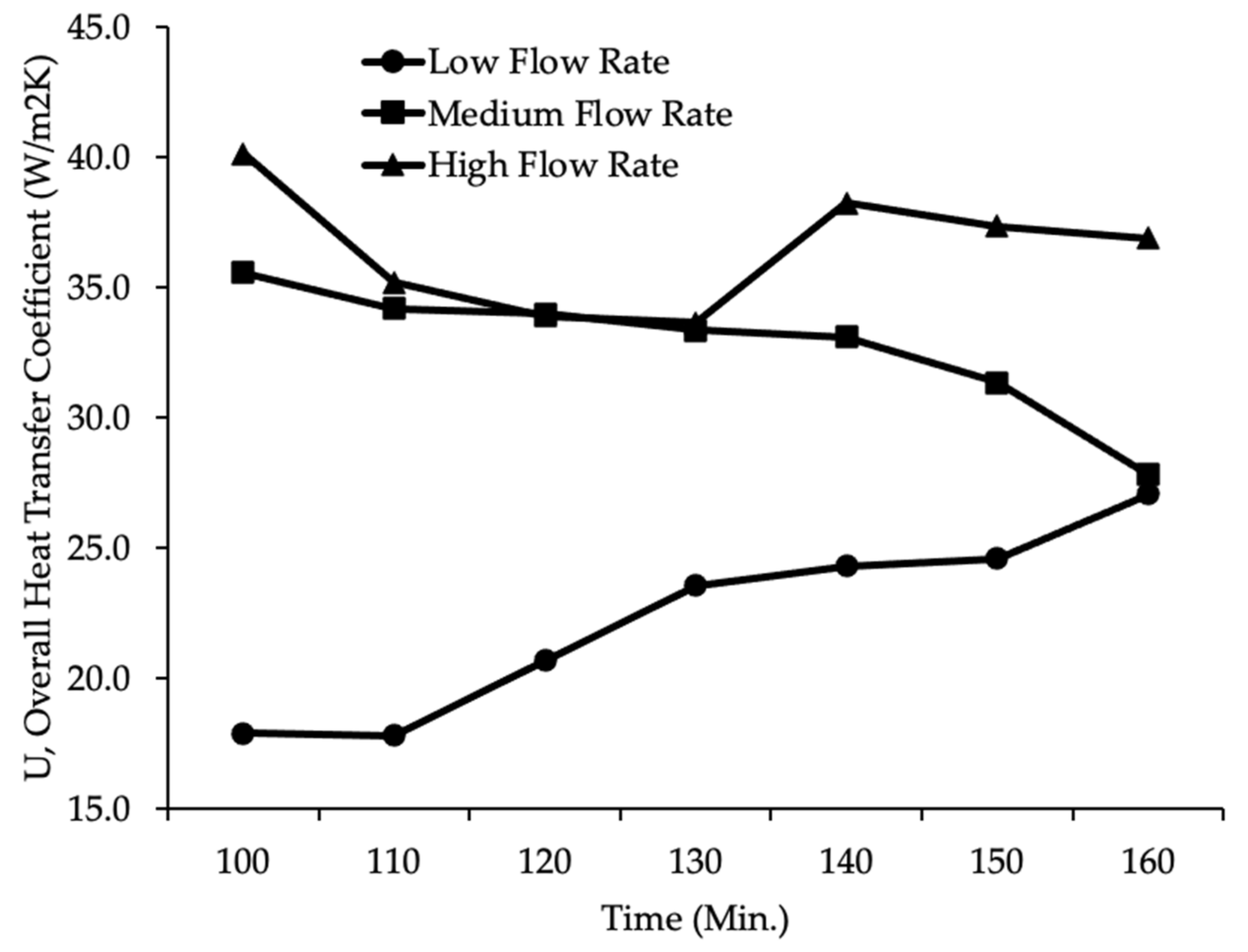
As shown in Figure 7, the overall heat transfer coefficient of the pilot-scale STHE system was between 17.9 to 27.0 W/m2 K, 27.8 to 35.6 W/m2 K, and 36.9 to 40.1 W/m2 K for low, medium, and high flow rates, respectively. It was also discovered that higher water flow rates had relatively higher overall heat transfer coefficients. Results also indicated that the CMTD increased from 214.8 to 232.8 °C at lower flow rates, 177.8 to 235.8 °C at medium flow rates, and 161.6 to 218.2 °C at high flow rates, after 160 min of the co-combustion process. Lower CMTD coincides with higher overall heat transfer at a high flow rate (18.2–18.5 L/min) within the same combustion time. In the meantime, higher water flow rates on the tube side generated high velocity and turbulence flow with a high Reynolds number and convective heat transfer coefficients on the tube side, ultimately leading to a higher overall heat transfer coefficient. An interesting trend is observed where the overall heat transfer coefficient was increased at a lower flow rate while overall heat transfer coefficients were decreased at both medium and high flow rate with increasing combustion times. Ultimately, the gap became smaller after 160 min poultry litter and natural gas co-combustion processes.
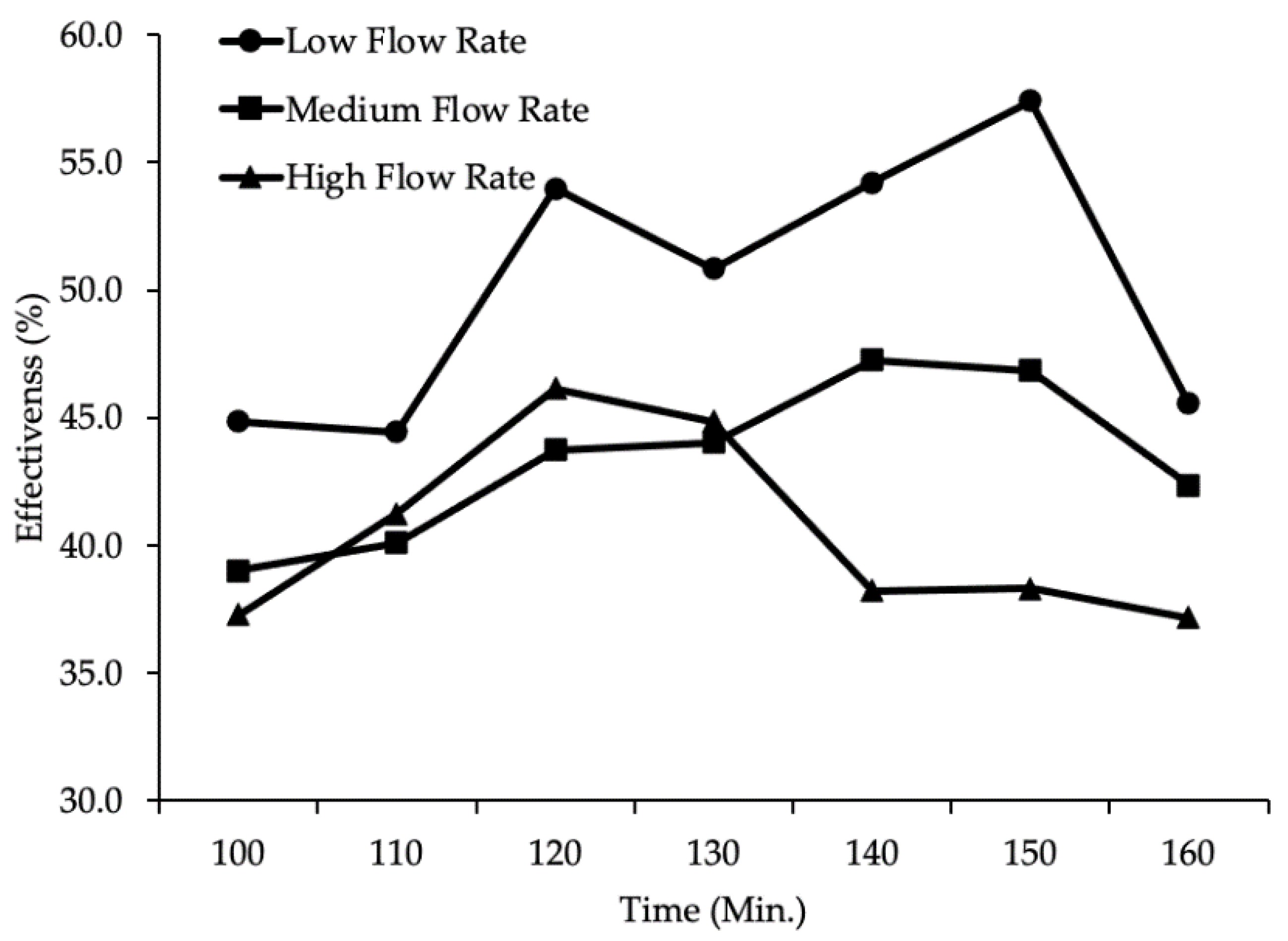
As shown in Figure 8, the effectiveness of the pilot-scale STHE system was further analyzed and ranged from 0.444 and 0.574 for low water flow rate, 0.390 to 0.473 for medium water flow rate, and 0.373 to 0.461 for high water flow rate. It was found that the effectiveness of the pilot-scale STHE system decreased when water flow rates were increased. It is postulated that the medium and higher water flow rates reduced the residence time of water on the tube and passed tube sections without effectively gaining heat from hot flue gas on the shell side. Experimental results indicated that inlet temperature of cold water on the tube side increased from 20 to 47.8 for low water flow rate, 45.0 for medium flow rate, and 45.0 for high flow rate, after 160 min co-combustion process. Therefore, the low flow rate achieved a high inlet temperature of the cold fluid (about 2.8 higher) and thereby caused a lower temperature difference with an inlet temperature of hot flue gas (around 504 ), ultimately reducing the maximum possible heat transfer rate (Qmax). On the other hand, the actual heat transfer rate (Qactual) increased by 55.1% (from 13.62 to 21.12), 37.5% (from 16.04 to 22.06), and 35.1% (from 15.05 to 20.34) for low, medium, and high flow rate, respectively. Thus, a low flow rate is the optimal water flow rate that enabled appropriate velocity and enough residence time of cold water on the tube side to gain heat from hot flue gas in the shell. In the meantime, a low flow rate provided a lower maximum possible heat transfer rate with a higher actual heat transfer rate to quickly achieve heat equilibrium between the two mediums and ultimately increase the effective performance of the pilot-scale STHE system. The current study concluded that the pilot-scale STHE system had an optimal heating performance under the lowest water flow rates (13.7–14.1 L/min), while the lab-scale STHE system experienced optimal performance under different water flow rates (about 6.44 L/min) [28]. Thus, these results infer that optimal water flow rates should be found for different size and capacity STHE systems by controlling mass flow rates on the tube side.
3.5. Effect of Parallel and Serial Arrangement of Water-to-Air Heaters
As shown in Figure 9, it was found that the inlet temperature of the water-to-air heater increased from 20 to 49.4 under a parallel arrangement, while it increased to 45.0 under serial arrangement after 160 min co-combustion process. In the meantime, the parallel arrangement increased trailer temperature from 10.6 to 82.2 , while the serial arrangement increased trailer temperature to 77.9 under similar outside temperature (between 8.3 and 9.4 ). Results show that the parallel arrangement of the water-to-air heaters caused the overall heat transfer coefficient of the STHE to vary from 33.7 to 40.6 W/m2 K, while a serial arrangement caused the overall heat transfer coefficient of the STHE to range from 28.5 to 34.2 W/m2K. To that end, these results indicate that the parallel arrangement performed better than the serial arrangement in terms of the increased inlet temperature of the heater (equivalent to outlet temperature of the STHE), trailer temperature, and the overall heat transfer coefficient. The parallel arrangement of heaters had a slightly faster dynamic response and demonstrated a higher heat transfer rate of 0.5% to 1.9% (about 0.1 to 0.4 MJ/h). Therefore, a parallel arrangement allowed the water-to-air heaters to reject slightly more heat from the hot water into the cold air in the empty trailer and increased trailer temperature by 4.3 . Moreover, a parallel arrangement allowed the pilot-scale STHE system to collect more heat from hot flue gas into the cold water being returned.
Limitation of study may include the estimation of flue gas mass flow rate to predict heat transfer rate and assumption of gas compositions during the poultry litter and natural gas co-combustion process to calculate the specific heat of flue gas. In the future study, the mass flow rate of flue gas can be measured using relatively expensive mass flow meters to compare with estimated flue gas mass flow rates and precisely derive heat transfer rate. Real-time gas compositions under various operating conditions of the co-combustion process can also be measured using the emission analyzer and then used to calculate the more accurate specific heat of flue gas that ultimately assist in estimating heat transfer coefficients and evaluate the performance of the STHE system. To reduce a lot of time and vast expenditures on experiment study, CFD and simulation tool can also be adopted to model the STHE system and investigate the heat transfer, pressure drop, velocity distribution using flue gas as one of the working fluids under various operating conditions, such as tube types, tube arrangement, and tube materials.
4. Conclusions
In this study, the pilot-scale shell and tube heat exchanger (STHE) prototype were specially designed and fabricated for the purpose of heat use in the flue gas from the poultry litter and natural gas co-combustion. The pilot-scale STHE prototype implemented twisted tubes and 40-degree segmental baffles to increase the heat transfer coefficient and maximize system performance. A systematic approach was then used to estimate heat transfer coefficients and investigate the performance of the STHE system. First, the specific heat of flue gas was calculated based on fuel properties, EA ratio, and flue gas temperature. Results indicated that the specific heat of flue gas during biomass co-combustion ranging between 1.044 and 1.338 kJ/kgK was slightly lower than the specific heat of flue gas undergoing fossil fuel combustion. This was because the poultry litter as one of biomass had lower carbon and hydrogen content compared to fossil fuels. Results also indicated that the specific heat of flue gas was increased with decreasing excess air and increasing flue gas temperature. Then, the estimated specific heat was then applied to develop a simplified mathematical model for overall heat transfer coefficient prediction of the pilot-scale STHE system by the integration of two different methods. The developed model was found to have a relatively small average bias error (ABE) of 0.08% and an absolute average error (AAE) of 2.39% to predict the overall heat transfer coefficients. Afterward, the STHE system performance, including water and trailer temperatures, heat load, effectiveness, and overall heat transfer coefficient, were investigated under the variable operating conditions, such as water flow rates on the shell side, flue gas flow rates on the tube side, and the arrangement of the water-to-air heaters in the trailer. Results showed that the increments in flue gas mass flow rate on the shell side increased fluid velocity and convective heat transfer coefficient, ultimately improving the overall heat transfer coefficient and effectiveness of the STHE system. On the contrary, decreasing the mass flow rate of water on the tube side allowed sufficient residence time and higher actual heat transfer, resulting in a higher overall heat transfer coefficient and effectiveness. Moreover, it was found that a parallel arrangement of the water-to-air heater in the trailer contributed toward an increase in inlet temperature of the heater (equivalent to outlet temperature of the STHE), trailer temperature, and overall heat transfer coefficient when compared to a serial arrangement.
In a future study, analysis of the energy flow and heat transfer from the poultry litter co-combustion into the pilot-scale STHE system, water-to-air heaters, and trailer under variable operating conditions can be performed. In the long-term, hot water production from the STHE using flue gas during the poultry litter and natural gas co-combustion process can contribute to energy savings, reduction in disposal costs and environmental problems, and provide a pathway toward a promising and sustainable waste management option for poultry farmers.
Author Contributions
S.W.L. and X.Q. coordinated projects and received grants from the Maryland Industrial Partnerships (MIPS), Maryland Department of Natural Resources (DNR), and Office of Technology Transfer (OTT) at Morgan State University. In conceptualization phase, X.Q. conducted the literature reviews and found the research gaps. X.Q. and Y.Y. designed the approach to set up the testing facility. X.Q. and Y.Y. designed, fabricated, and assembled prototype with major components. X.Q. and Y.Y. collected and performed formal analysis of experimental results. X.Q. wrote the original draft manuscript. S.W.L. and X.Q. reviewed, edited, and provided his constructive comments and suggestions to improve the quality of the article. S.W.L. supervised and coordinated project. All authors have read and agreed to the published version of the manuscript.
Funding
This research was supported and partially funded by the Maryland Industrial Partnerships (MIPS), Maryland Department of Natural Resources (DNR), and Office of Technology Transfer (OTT) at Morgan State University on the subject of space heating system development for the poultry house.
Institutional Review Board Statement
Not applicable.
Informed Consent Statement
Not applicable.
Acknowledgments
Authors would like to acknowledge the MIPS office and DNR for an opportunity for the subject research and partial financial support. This research behind it would not have been possible without an efficient collaboration of our industry partner, CyKloburn Technologies, LLC. We are also grateful for the insightful comments offered by the Morgan State University OTT. In addition, the authors would like to appreciate the kind support of the research staff and facilities from the Center for Advanced Energy Systems and Environmental Control Technologies (CAESECT).
Conflicts of Interest
The authors declare no conflict of interest.
Nomenclature
| heat exchanger area (m2) | |
| specific heat (J/g°C) | |
| specific heat of flue gas (J/g°C) | |
| specific heat of water (J/g°C) | |
| minimum heat capacity rate (J/s°C) | |
| corrected effective mean temperature difference (°C) | |
| outside diameter of tube (mm) | |
| D | diameter (mm) |
| De | equivalent diameter (mm) |
| effectiveness (%) | |
| inner fouling factor by water (m2 K/W) | |
| outer fouling factor by flue gas (m2 K/W) | |
| F | temperature efficiency factor |
| h | convective heat transfer coefficient |
| convective heat transfer coefficient determined by water on tube side (W/m2 K) | |
| convective heat transfer coefficient caused by flue gas on shell side (W/m2 K) | |
| thermal conductivity (W/m K) | |
| logarithmic mean temperature difference (°C) | |
| mass flow rate (kg/s) | |
| mass flow rate of flue gas (kg/s) | |
| mass flow rate of water (kg/s) | |
| Nusselt number | |
| Prandtl number | |
| distance between centers of two pipes (mm) | |
| heat load (J/s) | |
| heat load of water (J/s) | |
| heat load of flue gas (J/s) | |
| maximum possible heat transfer rate (J/s) | |
| actual heat transfer rate (J/s) | |
| Re | Reynolds number |
| density (kg/m3) | |
| thermal conductivity of the tube material (W/m K) | |
| tube wall thickness (m) | |
| change in temperature (°C) | |
| t1 | water temperature at inlet (°C) |
| t2 | water temperature at outlet (°C) |
| T1 | flue gas temperature at inlet (°C) |
| T2 | flue gas temperature at outlet (°C) |
| inlet temperature of hot fluid (°C) | |
| inlet temperature of cold fluid (°C) | |
| overall heat transfer coefficient, first method (W/m2K) | |
| overall heat transfer coefficient, second method (W/m2K) | |
| V | velocity (m/h) |
| kinematic viscosity (m2/s) |
References
- Master, B.I.; Chunangad, K.S.; Boxma, A.J.; Karl, D.; Stehlik, P. Most frequently used heat exchangers from pioneering research to worldwide applications. Heat Transf. Eng. 2006, 27, 4–11. [Google Scholar] [CrossRef]
- Salahuddin, U.; Bilal, M.; Ejaz, H. A review of the advancements made in helical baffles used in shell and tube heat exchangers. Int. Commun. Heat Mass 2015, 67, 104–108. [Google Scholar] [CrossRef]
- Duan, Z.; Shen, F.; Cao, X.; Zhang, J. Comprehensive effects of baffle configuration on the performance of heat exchanger with helical baffles. Nucl. Eng. Des. 2016, 300, 349–357. [Google Scholar] [CrossRef]
- Dubey, V.V.P.; Verma, R.R.; Verma, P.S.; Srivastava, A.K. Performance analysis of shell and tube type heat exchanger under the effect of varied operating condition. IOSR J. Mech. Civ. Eng. 2014, 11, 8–17. [Google Scholar] [CrossRef]
- Li, X.; Zhu, D.; Yin, Y.; Liu, S.; Mo, X. Experimental study on heat transfer and pressure drop of twisted oval tube bundle in cross flow. Exp. Therm. Fluid Sci. 2009, 99, 251–258. [Google Scholar] [CrossRef]
- Tan, X.H.; Zhu, D.S.; Zhou, G.Y.; Zeng, L.D. Experimental and numerical study of convective heat transfer and fluid flow in twisted oval tubes. Int. J. Heat Mass Transf. 2012, 55, 4701–4710. [Google Scholar] [CrossRef]
- Tan, X.H.; Zhu, D.S.; Zhou, G.Y.; Zeng, L.D. Heat transfer and pressure drop performance of twisted oval tube heat exchanger. Appl. Therm. Eng. 2013, 50, 374–383. [Google Scholar] [CrossRef]
- Zhang, J.F.; Li, B.; Huang, W.J.; Lei, Y.G.; He, Y.L.; Tao, W.Q. Experimental performance comparison of shell-side heat transfer for shell-and-tube heat exchangers with middle-overlapped helical baffles and segmental baffles. Chem. Eng. Sci. 2009, 64, 1643–1653. [Google Scholar] [CrossRef]
- Bichkar, P.; Dandgaval, O.; Dalvi, P.; Godase, R.; Dey, T. Study of shell and tube heat exchanger with the effect of types of baffles. Procedia Manuf. 2018, 20, 195–200. [Google Scholar] [CrossRef]
- Thantharate, V.; Zodpe, D.B. Experimental and numerical comparison of heat transfer performance of twisted tube and plain tube heat exchangers. Int. J. Sci. Eng. Res 2013, 4, 1107–1113. [Google Scholar]
- Kasmir, J.; Joshi, S.M. Experimental study of a shell and tube heat exchanger for performance enhancement. In Proceedings of the 2015 International Conference on Technologies for Sustainable Development (ICTSD), Mumbai, India, 4–6 February 2015; pp. 1–3. [Google Scholar] [CrossRef]
- Emal, Q.M.; Elena, P. Overall energy balance and heat transfer in a shell and tube heat exchanger. In Proceedings of the ISER 109th International Conference, Ottawa, ON, Canada, 27–28 February 2018. [Google Scholar]
- Abdulmumuni, B.; Ayoade, A.; Buhari, O.; Olatunde, A.; Olaniyi, F. Design, fabrication and performance evaluation of a shell and tube heat exchanger for practical application. Eur. J. Eng. Technol. Res. 2020, 5, 835–845. [Google Scholar] [CrossRef]
- Ehyaei, M.A.; Ahmadi, A.; Rosen, M.A.; Davarpanah, A. Thermodynamic Optimization of a Geothermal Power Plant with a Genetic Algorithm in Two Stages. Processes 2020, 8, 1277. [Google Scholar] [CrossRef]
- Coskun, C.; Oktay, Z.U.H.A.L.; Ilten, N. A new approach for simplifying the calculation of flue gas specific heat and specific exergy value depending on fuel composition. Energy 2009, 34, 1898–1902. [Google Scholar] [CrossRef]
- Cengel, Y. Heat and Mass Transfer: Fundamentals and Applications; McGraw-Hill Higher Education: New York, NY, USA, 2014. [Google Scholar]
- Menghini, D.; Marra, F.S.; Allouis, C.; Beretta, F. Effect of excess air on the optimization of heating appliances for biomass combustion. Exp. Therm. Fluid Sci. 2008, 32, 1371–1380. [Google Scholar] [CrossRef]
- Chandok, J.S.; Kar, I.N.; Tuli, S. Estimation of furnace exit gas temperature (FEGT) using optimized radial basis and back-propagation neural networks. Energy Convers. Manag. 2008, 49, 1989–1998. [Google Scholar] [CrossRef]
- El-Shafie, M.; Bassiouny, M.K.; Kambara, S.; El-Behery, S.M.; Hussien, A.A. Design of a heat recovery unit using exhaust gases for energy savings in an absorption air conditioning unit. Appl. Therm. Eng. 2021, 117031. [Google Scholar] [CrossRef]
- Patel, M.; Zhang, X.; Kumar, A. Techno-economic and life cycle assessment on lignocellulosic biomass thermochemical conversion technologies: A review. Renew. Sustain. Energy Rev. 2016, 53, 1486–1499. [Google Scholar] [CrossRef]
- Saidur, R.; Abdelaziz, E.A.; Demirbas, A.; Hossain, M.S.; Mekhilef, S. A review on biomass as a fuel for boilers. Renew. Sustain. Energy Rev. 2011, 15, 2262–2289. [Google Scholar] [CrossRef]
- Qian, X. Statistical Analysis and Evaluation of the Advanced Biomass and Natural Gas Co-Combustion Performance. Ph.D. Thesis, Morgan State University, Baltimore, MD, USA, 2019. [Google Scholar]
- Lynch, D.; Henihan, A.M.; Bowen, B.; Lynch, D.; McDonnell, K.; Kwapinski, W.; Leahy, J.J. Utilisation of poultry litter as an energy feedstock. Biomass Bioenergy 2013, 49, 197–204. [Google Scholar] [CrossRef] [Green Version]
- Zhu, S.; Lee, S.W. Co-combustion performance of poultry wastes and natural gas in the advanced Swirling Fluidized Bed Combustor (SFBC). Waste Manag. 2005, 25, 511–518. [Google Scholar] [CrossRef]
- Si, Q.; Xia, Q.; Liang, L.H.; Li, D.X. Investigation of heat transfer and flow resistance on twisted tube heat exchanger. J. Chem. Ind. Eng. (China) 1995, 46, 601–608. [Google Scholar]
- Davarpanah, A.; Zarei, M.; Valizadeh, K.; Mirshekari, B. CFD design and simulation of ethylene dichloride (EDC) thermal cracking reactor. Energ. Sources Part A 2019, 41, 1573–1587. [Google Scholar] [CrossRef]
- Valizadeh, K.; Farahbakhsh, S.; Bateni, A.; Zargarian, A.; Davarpanah, A.; Alizadeh, A.; Zarei, M. A parametric study to simulate the non-Newtonian turbulent flow in spiral tubes. Energy Sci. Eng. 2020, 8, 134–149. [Google Scholar] [CrossRef] [Green Version]
- Wang, W.; Shuai, Y.; Li, B.; Li, B.; Lee, K.S. Enhanced heat transfer performance for multi-tube heat exchangers with various tube arrangements. Int. J. Heat Mass Transf. 2021, 168, 120905. [Google Scholar] [CrossRef]
- Qian, X.; Yang, Y.; Lee, S.W. Design and Evaluation of the Lab-Scale Shell and Tube Heat Exchanger (STHE) for Poultry Litter to Energy Production. Processes 2020, 8, 500. [Google Scholar] [CrossRef]
- Qian, X.; Lee, S.; Chandrasekaran, R.; Yang, Y.; Caballes, M.; Alamu, O.; Chen, G. Electricity Evaluation and Emission Characteristics of Poultry Litter Co-Combustion Process. Appl. Sci. 2019, 9, 4116. [Google Scholar] [CrossRef] [Green Version]
- Katsaros, G.; Sommersacher, P.; Retschitzegger, S.; Kienzl, N.; Tassou, S.A.; Pandey, D.S. Combustion of poultry litter and mixture of poultry litter with woodchips in a fixed bed lab-scale batch reactor. Fuel 2021, 286, 119310. [Google Scholar] [CrossRef]
- Kays, W.M.; Perkins, H.C. Handbook of Heat Transfer; Rohsenow, W.M., Hartnett, J.P., Eds.; McGraw-Hill: New York, NY, USA, 1972. [Google Scholar]
- Moran, M.J.; Shapiro, H.N.; Boettner, D.D.; Bailey, M.B. Fundamentals of Engineering Thermodynamics; John Wiley & Sons: New York, NY, USA, 2010. [Google Scholar]
- Houshfar, E.; Skreiberg, Ø.; Løvås, T.; Todorović, D.; Sørum, L. Effect of excess air ratio and temperature on NOx emission from grate combustion of biomass in the staged air combustion scenario. Energy Fuels 2011, 25, 4643–4654. [Google Scholar] [CrossRef]
- Qian, X.; Lee, S.; Soto, A.-M.; Chen, G. Regression model to predict the higher heating value of poultry waste from proximate analysis. Resources 2018, 7, 39. [Google Scholar] [CrossRef] [Green Version]
Figure 1.
Approach to estimate specific heat and overall heat transfer coefficient.

Figure 2.
Pilot-scale shell and tube heat exchanger (STHE) system, fabrication, and assembly.

Figure 3.
Experimental setup and operating conditions for the pilot-scale STHE system evaluation.

Figure 4.
Gas composition in the flue gas under various EA ratios.

Figure 5.
Specific heat of flue gas under various EA ratios and flue gas temperatures.

Figure 6.
Performance of the STHE under various mass flow rates of flue gas on the shell side. (a) Feeding rate of poultry litter at 5.76 kg/h. (b) Feeding rate of poultry litter at 6.81 kg/h.
Figure 6.
Performance of the STHE under various mass flow rates of flue gas on the shell side. (a) Feeding rate of poultry litter at 5.76 kg/h. (b) Feeding rate of poultry litter at 6.81 kg/h.

Figure 7.
Overall heat transfer coefficients under various water flow rates on the tube side.

Figure 8.
Effectiveness under various water flow rates on the tube side.

Figure 9.
Effect of water-to-air heater arrangement on the system performance.


Table 1.
Investigation of twisted tubes with various tube parameters and working fluids.
| Tube Parameters (mm) | Working Fluid | Reference | ||||
|---|---|---|---|---|---|---|
| Thickness | Pitch | A | B | Tube | Shell | |
| 3.0 | 144, 192, 205 | 21 | - | Diesel | Steam | [5] |
| 2.5 | 200 | 29 | 19.5 | Cold water | Hot water | [6] |
| 2.5 | 230 | 29 | 19.5 | Cold water | Hot water | [7] |
| - | 90 | 18.42 | 12 | Water | Air | [10] |
| 2.0 | 300 | 33 | 16 | Water | Air | [25] |
Table 2.
Estimation of overall heat transfer coefficients (U1) using the first method.
| Flue Gas Temp. (°C) | Water Temp. (°C) | Cp at Avg. Temp. | Heat Load | CMTD | U1 | |||
|---|---|---|---|---|---|---|---|---|
| Inlet | Outlet | kg/h | Inlet | Outlet | kJ/kgK | MJ/h | °C | W/m2K |
| 479.0 | 126.0 | 80.1 | 42.2 | 46.7 | 1.118 | 31.6 | 201.8 | 42.1 |
| 489.0 | 130.0 | 89.5 | 43.3 | 47.8 | 1.122 | 36.1 | 207.0 | 46.8 |
| 492.0 | 135.0 | 89.5 | 44.4 | 48.9 | 1.125 | 35.9 | 210.9 | 45.8 |
| 474.0 | 136.0 | 89.5 | 45.0 | 49.4 | 1.119 | 33.9 | 205.7 | 44.2 |
| 489.0 | 144.0 | 89.5 | 46.1 | 50.6 | 1.127 | 34.8 | 215.8 | 43.3 |
| 499.0 | 150.0 | 98.8 | 46.1 | 51.1 | 1.132 | 39.1 | 223.6 | 46.9 |
| 489.0 | 150.0 | 98.8 | 46.1 | 50.6 | 1.129 | 37.8 | 220.7 | 46.0 |
| 481.0 | 151.0 | 98.8 | 46.1 | 51.1 | 1.127 | 36.7 | 218.9 | 45.1 |
Table 3.
Estimation of overall heat transfer coefficients (U2) using the second method.
| hi (W/m2K) | ho (W/m2K) | U2 (W/m2K) | U1 (W/m2K) | Uest. (W/m2K) | Errors (%) | |
|---|---|---|---|---|---|---|
| 42.73 | 235.0 | 33.9 | 42.1 | 34.3 | ABE 1 = 0.08 | AAE 2 = 2.39 |
| 46.8 | 235.57 | 36.5 | 46.8 | 38.1 | ||
| 46.87 | 236.1 | 36.5 | 45.8 | 37.3 | ||
| 46.73 | 236.37 | 36.5 | 44.2 | 36 | ||
| 46.92 | 236.92 | 36.6 | 43.3 | 35.3 | ||
| 51.0 | 237.0 | 39.0 | 46.9 | 38.2 | ||
| 50.84 | 236.92 | 38.9 | 46 | 37.5 | 3.73 | |
| 50.77 | 237.0 | 38.9 | 45.1 | 36.7 | 5.60 | |
1 ABE = average bias error; 2 AAE = absolute bias error.
Publisher’s Note: MDPI stays neutral with regard to jurisdictional claims in published maps and institutional affiliations. |
© 2021 by the authors. Licensee MDPI, Basel, Switzerland. This article is an open access article distributed under the terms and conditions of the Creative Commons Attribution (CC BY) license (https://creativecommons.org/licenses/by/4.0/).
Share and Cite
MDPI and ACS Style
Qian, X.; Lee, S.W.; Yang, Y. Heat Transfer Coefficient Estimation and Performance Evaluation of Shell and Tube Heat Exchanger Using Flue Gas. Processes 2021, 9, 939. https://doi.org/10.3390/pr9060939
AMA Style
Qian X, Lee SW, Yang Y. Heat Transfer Coefficient Estimation and Performance Evaluation of Shell and Tube Heat Exchanger Using Flue Gas. Processes. 2021; 9(6):939. https://doi.org/10.3390/pr9060939
Chicago/Turabian StyleQian, Xuejun, Seong W. Lee, and Yulai Yang. 2021. "Heat Transfer Coefficient Estimation and Performance Evaluation of Shell and Tube Heat Exchanger Using Flue Gas" Processes 9, no. 6: 939. https://doi.org/10.3390/pr9060939
Note that from the first issue of 2016, this journal uses article numbers instead of page numbers. See further details here.