Applied Cleaning Methods of Oil Residues from Industrial Tanks


Abstract
:1. Introduction
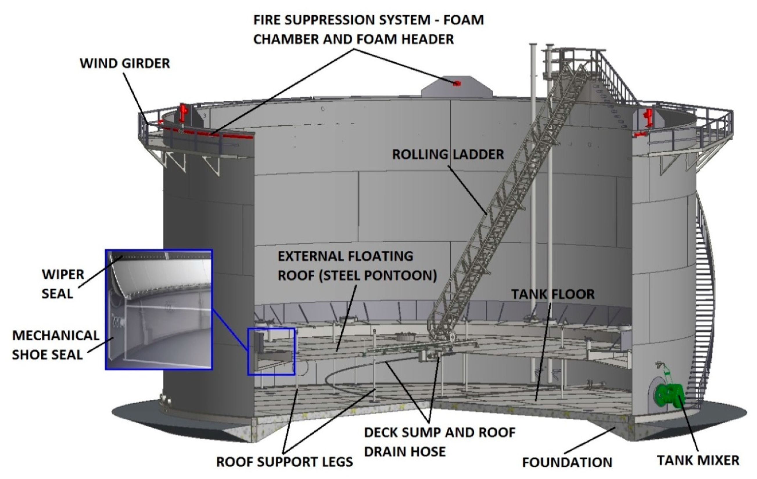
1.1. Industrial Tanks for Oil Storage
1.2. Cleaning of Industrial Oil Tanks
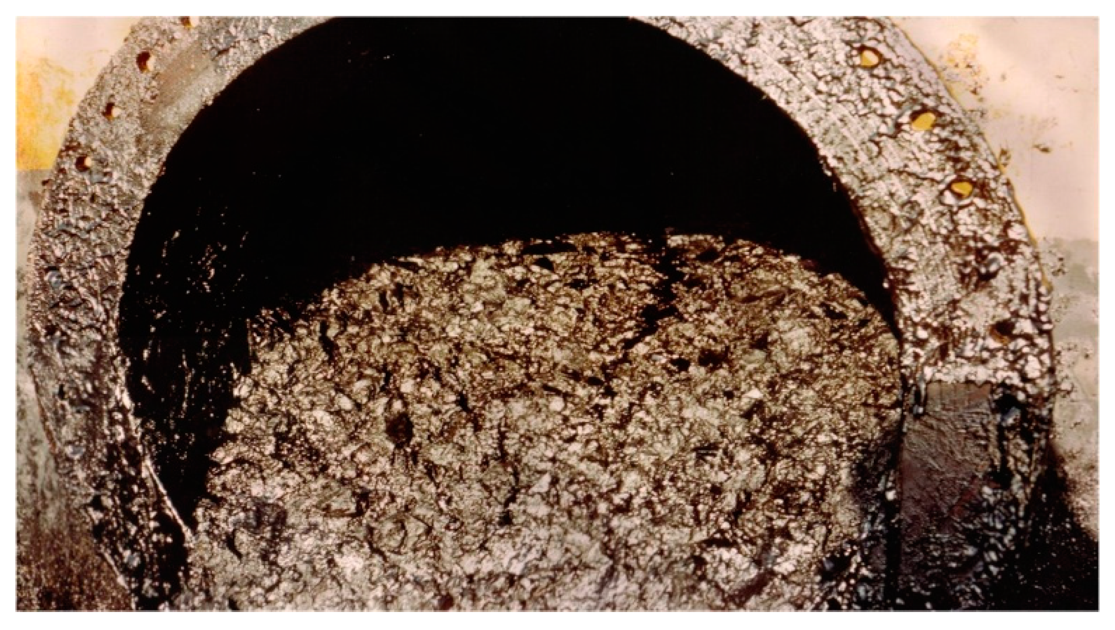
1.3. Composition of Tank Bottom Oil Residues
2. Crude Oil and Petroleum Sludge
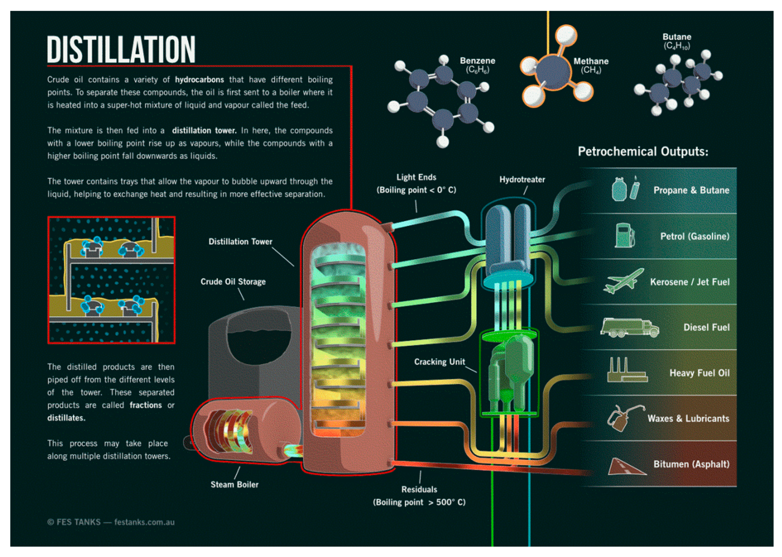
2.1. Crude Oil
- Paraffins (Saturated Hydrocarbons-Alkanes (e.g., octane) with formula CnH2n+2)
- Olefins (unsaturated hydrocarbons-alkenes (e.g., pentene) with formula CnH2n)
- Naphthenes or cycloparaffins (Saturated Hydrocarbons-Cycloalkanes (e.g., cyclohexane) of general formula CnH2)
- Aromatic hydrocarbons (arenes (e.g., benzene))
- Sweet crude oil: Sulfur < 0.5%
- Sour crude oil: Sulfur > 0.5%
- Extractive desulfurization
- Oxidative desulfurization
- Biodesulfurization
- Desulfurization through alkylation
- Chlorinolysis
- By using supercritical water
- Low resins-to-asphaltene ratios
- Temperature and pressure reduction
- Combining certain crudes
- Gas lifting (enhanced oil recovery (EOR) with natural gas or CO2)
- Shear effects and electronic effects during flow
2.2. Petroleum Sludge
3. Oil Tanks Cleaning Methods
3.1. General
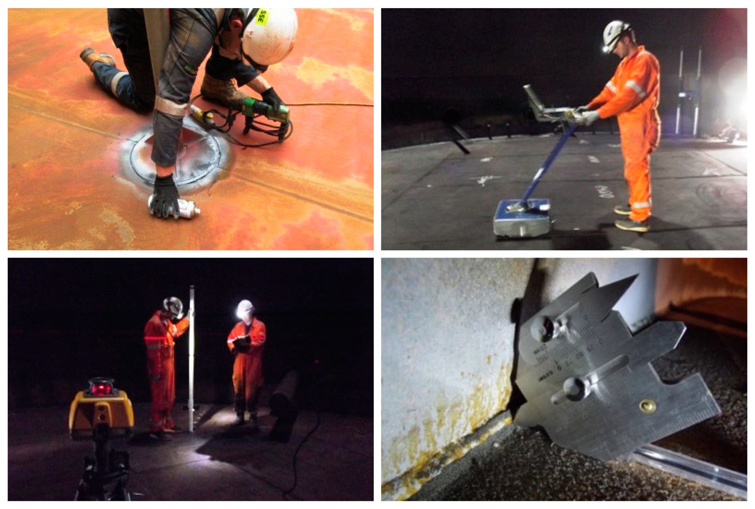
3.2. Manual Cleaning
- Low cleaning efficiency
- Work is conducted in a confined space
- Workers must wear heavy personal protective equipment with breathing apparatus
- Working is only possible for a few minutes
- Manual removal of the sludge
- Utilizing high-pressure water jetting
- The value of the oil is lost together with the sludge
- High amounts of waste (water, sludge, oil) are generated which need to be disposed of
- There is significant use of equipment and manpower
- Health and Safety Executive (HSE) concern applies during the job execution
- Downtime is huge
- Skilled workers for the job are limited and difficult to find
- Cost impact might be multiple times that of the mechanical cleaning cost
3.3. Automated (Non-Human-Entry-Mechanical) Cleaning
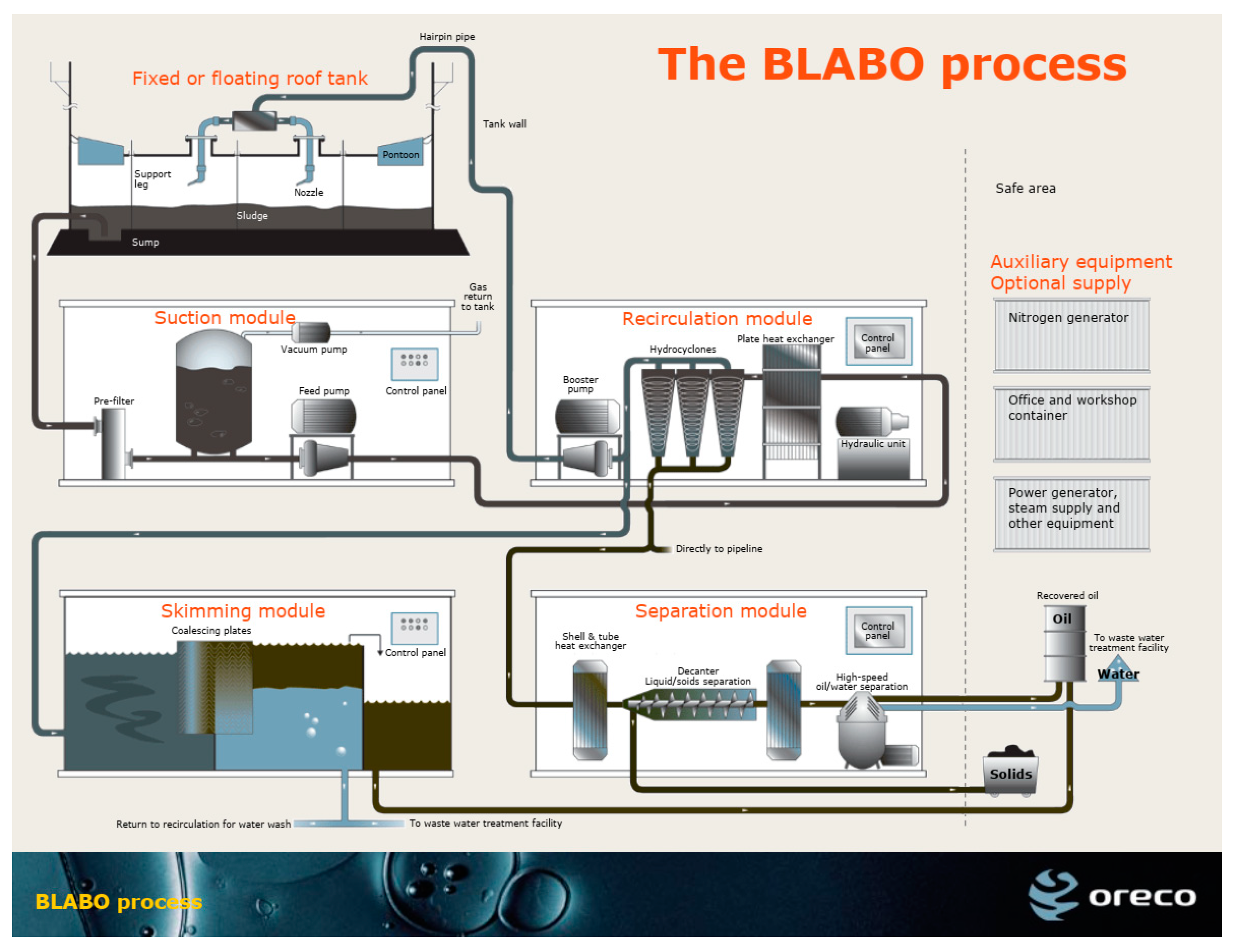
3.3.1. ORECO’s BLABO System
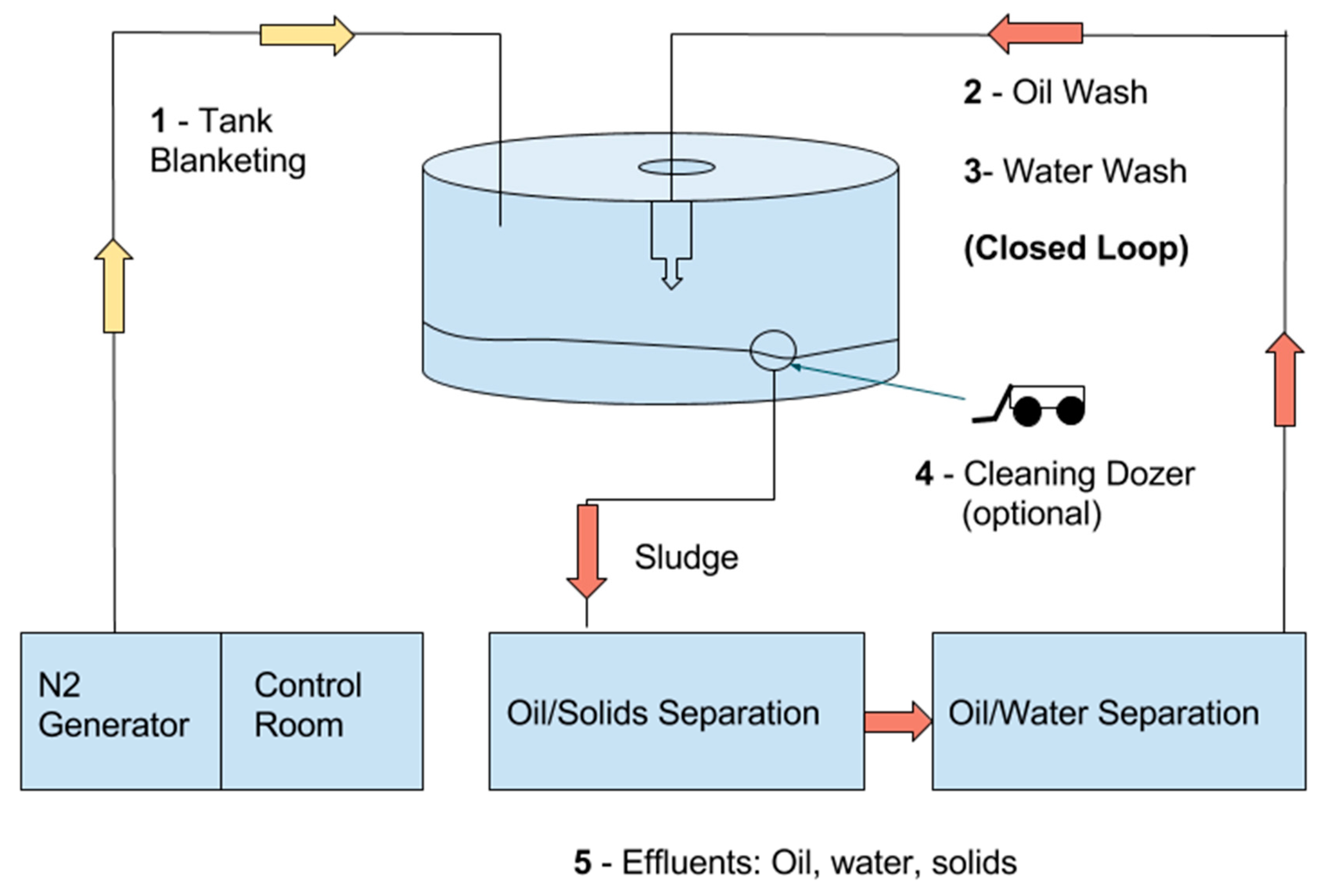
3.3.2. Zaopin Technologies COW System
- Blanketing of the tank with nitrogen until the oxygen level drops below 8%
- Liquefaction-disintegration of the sludge with recirculation oil (cleaning media) that is sprayed through cleaning nozzles
- Pumping the sludge from the bottom of the tank
- Separate the sludge from water–solids and recover the pure oil contained therein
- Final cleaning with water recirculation
- (Optional). Use a hydraulically powered specialized cleaning dozer that enters through a nozzle and is easily assembled in the tank and handled by only one person to remove the very heavy deposits that failed to be suctioned
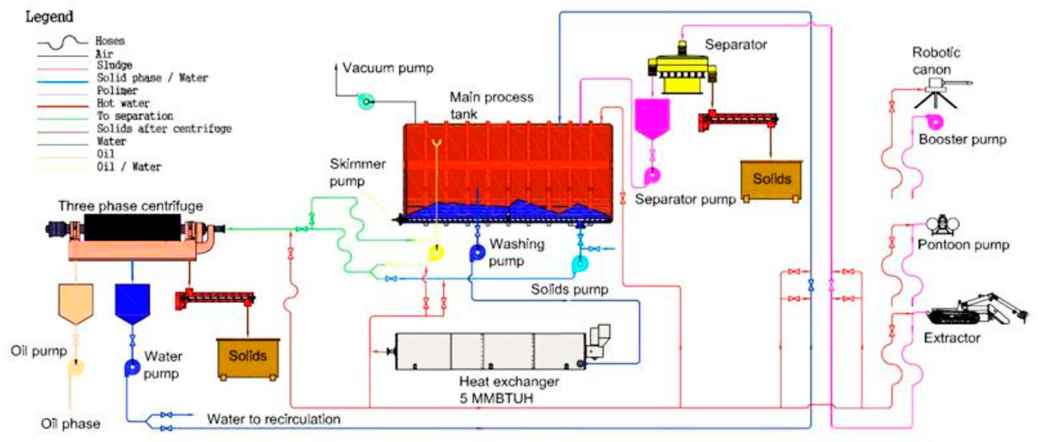
3.3.3. KMT’s MEGAMACS system
3.4. Robotic Cleaning
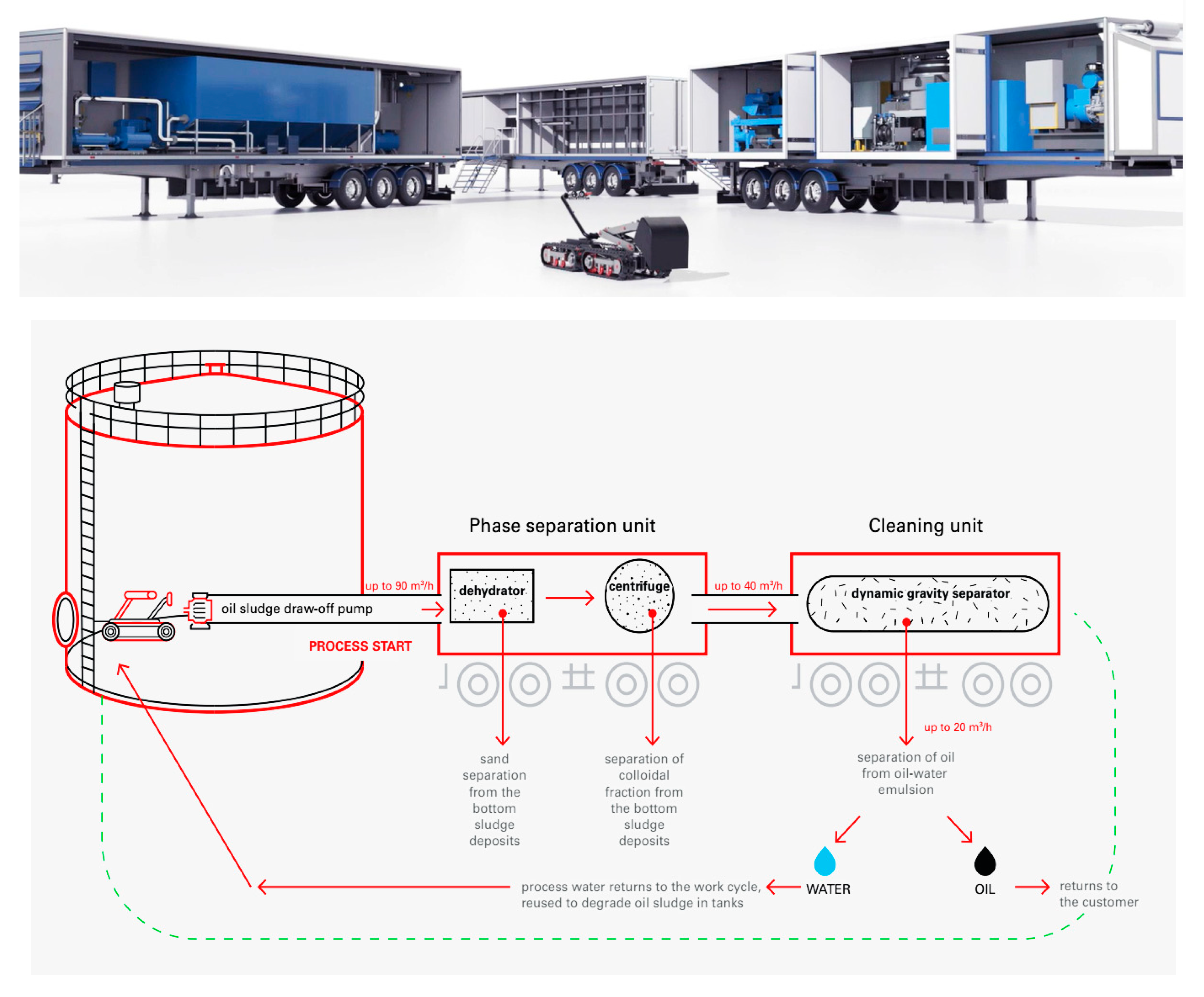
MIRRICO’s MARTin Oil Tech System
- Block for bottom sediments’ extraction and washing of internal surfaces from oil deposits
- Block for cleaning and processing (phase separation) of sediments
- Block for storage and transportation of additional equipment and bandaging materials.
- A fourth block for the disposal (neutralization) of oil waste and water treatment is under development by the “MIRRICO” Group [46].
4. Results and Discussion
4.1. Performance of Cleaning Methods
4.1.1. Manual Cleaning
4.1.2. Automated (Non-Human-Entry-Mechanical) Cleaning
ORECO’s BLABO System
ZAOPIN Technologies COW System
KMT’s MEGAMACS System
- Oil sludge pits and lagoon cleaning
- Catalysts storage tank cleaning
- Railroad tanker cleaning
- Cleaning of various vessels, barges, etc.
4.1.3. Robotic Cleaning
MIRRICO’s MARTin Oil Tech System
4.2. Safety of Cleaning Methods
4.2.1. Manual Cleaning
4.2.2. Automated (Non-Human-Entry-Mechanical) Cleaning
4.2.3. Robotic Cleaning
- No personnel entry into the tank is required at any stage of the process
- All equipment is hydraulically driven
- No electrical components inside the tank
- Tank blanketing is not required
- It does not generate static electricity
- The system can be installed up to 150 m away from the tank
- It has a common ground with the tank and shuts down if there is a problem in the circuit
- The system is stored into semitrailers which are very well insulated and is equipped with air conditioning, protecting the staff from very low or high temperatures.
4.3. Environmental Impact of Cleaning Methods
4.3.1. Manual Cleaning
4.3.2. Automated (Non-Human-Entry-Mechanical) Cleaning
4.3.3. Robotic Cleaning
4.4. Cost of Cleaning Methods
4.4.1. Manual Cleaning
- Tank cleaning cost: 100 $/m3
- Cost of disposal of oil sludge: 127.5 $/m3
- Total cost of tank cleaning: 227.5 $/m3
4.4.2. Automated (Non-Human-Entry-Mechanical) Cleaning
4.4.3. Robotic Cleaning
5. Conclusions
- The faster cleaning system is the automated (mechanical) MEGAMACS with sludge extractor. All other automated and robotic systems in terms of time present very little deviation from each other and provide the same cleaning quality. Manual cleaning ends up being the slowest and most painful cleaning method.
- As far as safety is concerned, the MARTin robotic cleaning system reaches the top, being the only exception where the presence of people inside the tank is not necessary at any stage of cleaning. In all other methods, entering the tank, at one of the cleaning stages, is mandatory.
- The most dangerous and harmful cleaning method is the manual one, in which the presence of people inside the tank is required from the beginning to the end of the process.
- From an environmental point of view, all automated (mechanical) and robotic systems have closed loop cleaning circuits and a very efficient hydrocarbon recovery system. The only method that cleans with an open system and does not recycle the produced waste is the manual one, which is significantly burdening not only people but also the environment.
- MARTin and MEGAMACS have the lowest cleaning costs, while BLABO is the most expensive.
- The modern need in the field of industrial tank cleaning focuses on inventing methods that clean in a short time, with an automated system that does not require people to enter the interior of the tank, with the ability to recover almost all hydrocarbons from the wastes in the lower cost.
Author Contributions
Funding
Acknowledgments
Conflicts of Interest
References
- Energy East Pipeline Ltd. Tank Terminals-General Design. Consol. Appl. 2016, 6, 16. [Google Scholar]
- PetroWiki. Floating Roof Tanks. Available online: https://petrowiki.org/Floating_roof_tanks (accessed on 4 March 2020).
- Thanh, N.X.; Hsieh, M.; Philp, R.P. Waxes and asphaltenes in crude oils. Org. Geochem. 1999, 30, 119–132. [Google Scholar] [CrossRef]
- Kleinfeld, M.; Feiner, B. Health Hazards Associated with Work in Confined Spaces. J. Occup. Environ. Med. 1966, 8, 358–364. [Google Scholar]
- Scott, S. Conventional and Non Man-Entry Tank Desludging and Cleaning. Available online: http://scott7.com/tank-desludging-cleaning/ (accessed on 7 March 2020).
- Philemon Ze Bilo’o, M.B.N. Christelle Solange Jessie Ekoka, Characterization of Oily Sludge from Cameroon Petroleum Refinery. Int. J. Emerg. Eng. Res. Technol. 2016, 4, 34–38. [Google Scholar]
- PennState College of Earth and Mineral Sciences Chemical Constitution of Crude Oil. Available online: https://www.e-education.psu.edu/fsc432/node/5 (accessed on 3 March 2020).
- Demirbas, A.; Alidrisi, H.; Balubaid, M.A. API Gravity, Sulfur Content, and Desulfurization of Crude Oil. Pet. Sci. Technol. 2015, 33, 93–101. [Google Scholar] [CrossRef]
- URET Distillation of Crude Oil & Oil Products. Available online: https://uret.com.tr/en/uret-blog-en/distillation-of-crude-oil-oil-products/ (accessed on 4 March 2020).
- Leontaritis, K.J.; Ali Mansoori, G. Asphaltene deposition: A survey of field experiences and research approaches. J. Pet. Sci. Eng. 1988, 1, 229–239. [Google Scholar] [CrossRef]
- Carnahan, N.; Salager, J.L.; Anton, R. Effect of Resins on Stability of Asphaltenes. In Offshore Technology Conference; Offshore Technology Conference: Houston, TX, USA, 2007; p. 9. [Google Scholar]
- Izquierdo, A.; Rivas, O. A Global Approach to Asphaltene Deposition Problems. In International Symposium on Oilfield Chemistry; Society of Petroleum Engineers: Houston, TX, USA, 1997; p. 8. [Google Scholar]
- Speight., J.G. Petroleum Asphaltenes—Part 1: Asphaltenes, Resins and the Structure of Petroleum. Oil Gas Sci. Technol. Rev. D’ifp Energ. Nouv. Inst. Français Du Pétrole. 2004, 59, 467–477. [Google Scholar] [CrossRef] [Green Version]
- WPenvironmental SOR (Sludge Oil Recovery Unit). Available online: https://www.wpenvironmental.com/sludge-oil-recovery-unit/#iLightbox[gallery_image_1]/0 (accessed on 4 March 2020).
- Al-Futaisi, A.; Jamrah, A.; Yaghi, B.; Taha, R. Assessment of alternative management techniques of tank bottom petroleum sludge in Oman. J. Hazard. Mater. 2007, 141, 557–564. [Google Scholar] [CrossRef] [PubMed]
- Heidarzadeh, N.; Gitipour, S.; Abdoli, M.A. Characterization of oily sludge from a Tehran oil refinery. Waste Manag. Res. 2010, 28, 921–927. [Google Scholar] [CrossRef] [PubMed]
- Johnson, O.A.; Affam, A.C. Petroleum sludge treatment and disposal: A review. Environ. Eng. Res. 2019, 24, 191–201. [Google Scholar] [CrossRef]
- Mansur, A. Recovery and Characterization of Oil from Waste Crude Oil Tank Bottom Sludge from Azzawiya Oil Refinery in Libya. J. Adv. Chem. Eng. 2015, 5, 05. [Google Scholar] [CrossRef]
- SERVICES, W.O. Storage Tank Inspections. Available online: https://willacyoil.com/petrochemical-oil-refinery-services/storage-tank-inspections-non-destructive/ (accessed on 4 March 2020).
- Institution, A.P. Requirements for Safe Entry and Cleaning of Petroleum Storage Tanks; API Publishing Services: Washington, DC, USA, 2018. [Google Scholar]
- API. Guidelines and Procedures for Entering and Cleaning Petroleum Storage Tanks. In ANSI/API Recommended Practice 2016; API Publishing Services: Washington, DC, USA, 2006. [Google Scholar]
- NuovaSaimar Storage Tank Cleaning-Traditional Tank Cleaning Method. Available online: https://www.nuovasaimar.it/en/our-services/tank-cleaning/ (accessed on 4 March 2020).
- TRADEBE TRADITIONAL TANK CLEANING. Available online: https://www.tradebeindustrialservices.com/traditional-tank-cleaning (accessed on 3 March 2020).
- Westates Technologies, I. Complete Tank Cleaning & Sludge Removal Solutions. Available online: http://www.alltankcleaning.com/ (accessed on 3 March 2020).
- Al-Dousary, S.; Dharan, G.P.T. Implementation Of Non-man Entry Technology—An Automated Technology for De-sludging & Cleaning of Tanks. In SPE Kuwait Oil and Gas Show and Conference; Society of Petroleum Engineers: Mishref, Kuwait, 2015; p. 9. [Google Scholar]
- Oreco Tank Cleaning Process and Services. Available online: https://www.oreco.com/solutions/crude-oil-tank-cleaning/the-tank-cleaning-process/ (accessed on 3 March 2020).
- SlideShare Blabo Process. Available online: https://www.slideshare.net/Oreco/blabo-process (accessed on 3 March 2020).
- Tank Cleaning Services, The Blabo Process. Available online: https://www.oreco.com/solutions/crude-oil-tank-cleaning/the-tank-cleaning-process/ (accessed on 3 March 2020).
- Oreco Suction Module. Available online: https://www.oreco.com/solutions/crude-oil-tank-cleaning/how-blabo-works/suction-module/ (accessed on 3 March 2020).
- Oreco Recirculation Module. Available online: https://www.oreco.com/solutions/crude-oil-tank-cleaning/how-blabo-works/recirculation-module/ (accessed on 3 March 2020).
- Oreco Top Entry-Single Nozzle Sweeper for Efficient Tank Cleaning. Available online: https://www.oreco.com/media/1427/190321_oreco_sns_top_entry_brochure.pdf (accessed on 13 April 2020).
- Oreco Separation Module. Available online: https://www.oreco.com/solutions/crude-oil-tank-cleaning/how-blabo-works/separation-module/ (accessed on 3 March 2020).
- Oreco Oil Skimming Module. Available online: https://www.oreco.com/solutions/crude-oil-tank-cleaning/how-blabo-works/skimming-module/ (accessed on 3 March 2020).
- Yayla, S.; Sabah, S.; Olcay, A. Engineering Applications of Computational Fluid Mechanics Numerical investigation of coalescing plate system to understand the separation of water and oil in water treatment plant of petroleum industry Numerical investigation of coalescing plate system to understand the separation of water and oil in water treatment plant of petroleum industry. Eng. Appl. Comput. Fluid Mech. 2017, 11, 184–192. [Google Scholar]
- Oreco Customer Cases. Available online: https://www.oreco.com/references/customer-cases/ (accessed on 4 March 2020).
- VAOS Automated Hydrocarbon Recovery and Tank Cleaning (AHRTC) Services. Available online: http://www.vaos.com/en/services/services/4/automated-hydrocarbon-recovery-and-tank-cleaning-ahrtc-services.htm (accessed on 18 March 2020).
- Technologies, Z. Crude Oil Tank Cleaning Systems. Available online: http://www.zp-tec.com/products/crude-oil-tank-cleaning (accessed on 3 March 2020).
- KMT Mega Macs Tank Cleaning for Crude and Sludge Oil. Available online: https://kmt-tankcleaning.com/megamacs (accessed on 17 March 2020).
- Cleaning, K.-T. CUTTING-EDGE, MOBILE SLUDGE REMOVAL AND PROCESSING SYSTEM. Available online: https://kmt-tankcleaning.com/process (accessed on 15 March 2020).
- KMT Mega Macs Auxillary Equipment. Available online: https://kmt-tankcleaning.com/aux-equipment (accessed on 17 March 2020).
- Suleiman, O.M.E.; Osman, M.Y.; Kassala, S. Deflection of Rectangular Laminated Composite Plates using Dynamic Relaxation Method; LAPLAMBERT Academic Publishing, Member of Omni Scriptum Publishing Group: Latvia, Germany, 2007; ISBN 978-3-330-33164-8. [Google Scholar]
- Amirante, P.; Clodoveo, M.L.; Leone, A.; Tamborrino, A.; Patel, V.B. Chapter 10-Influence of Different Centrifugal Extraction Systems on Antioxidant Content and Stability of Virgin Olive Oil. In Olives and Olive Oil in Health and Disease Prevention; Preedy, V.R., Watson, R.R., Eds.; Academic Press: San Diego, CA, USA, 2010; pp. 85–93. [Google Scholar]
- Sanpeng, D.; Xiaoli, X.; Chongning, L.; Xinghui, Z. Research on the oil tank sludge cleaning robot system. In Proceedings of the 2010 International Conference on Mechanic Automation and Control Engineering, Wuhan, China, 26–28 June 2010. [Google Scholar]
- Group, A.T.K. Equipment Set for the Remotely-Controlled Removal of Sludge from Oil Tanks. Available online: https://www.adroctech.com/ (accessed on 14 March 2020).
- MARTin, MARTin-Innovative solution for no-man entry cleaning of tanks. Available online: https://www.mirrico.ru/en/services-products/products/robotic-method-of-stripping-petrochemical-equipmen (accessed on 14 March 2020).
- StockExpo MARTIN—Mobile Robotic Tank Cleaning Solution. Available online: https://www.stocexpo.com/en/products/martin-mobile-robotic-tank-cleaning-solution/ (accessed on 19 March 2020).
- Tech, M.O. Martin: Innovative Robotic. Unit for Cleaning Oil Tanks. Available online: https://martinoil.tech/ (accessed on 14 March 2020).
- MIRRICO Robotic Cleaning Method of Oilfield Equipment. Available online: https://www.mirrico.ru/en/services-products/products/robotic-method-of-stripping-oil-field-equipment-fr/#technologies (accessed on 19 March 2020).
- MIRRICO Comparative Calculation of the Economic Efficiency of Manual and Robotic Methods for Cleaning Oil Tanks. Available online: https://www.mirrico.ru/en/services-products/products/robotic-method-of-stripping-oil-field-equipment-fr/#calc (accessed on 20 March 2020).
- ORECO Changing from Manual to Automated Tank Cleaning Saved Time and Money. Available online: https://www.oreco.com/media/1093/cases-fawley-uk.pdf (accessed on 29 March 2020).


| Crude Oil Elements | Content% |
|---|---|
| Carbon | 79.5–87.1 |
| Hydrogen | 11.5–14.8 |
| Sulfur | 0.1–3.5 |
| Nitrogen | 0.1–0.5 |
| Oxygen | 0.1–0.5 |
| Metal | Petroleum Development Oman | Tehran Oil Refinery |
|---|---|---|
| Zinc | 278 mg/kg | 6100 mg/kg |
| Lead | 91 mg/kg | 850 mg/kg |
| Nickel | 7.5 mg/kg | 2700 mg/kg |
| Cadmium | Not Found | 100 mg/kg |
| Chromium | 12 mg/kg | Not Found |
| Mercury | 3.5 mg/kg | Not Found |
| Element | Content (%) |
|---|---|
| Oil content | 42.8 (±1.1) |
| Light (volatile) h/c in the oil content | 30.7(±0.07) |
| Non-volatile h/c in the oil content | 69.3 (±0.4) |
| Water content | 2.9 (±0.2) |
| Solid content | 55.2 (±0.6) |
| Organic matter in the solid content | 70 (±0.6) |
| Element | Content (%) |
|---|---|
| API Gravity | 33.03 |
| Density | 0.68 g/L |
| Kinetic viscosity at 70 F | 7.01 cSt |
| Kinetic viscosity at 100 F | 3.655 cSt |
| Ash content | 0.007 g/g oil |
| Salt content (NaCl) | 2.30 mg/L |
| Case Study | Tank Size | Average Sludge Height | Total Sludge Volume | Total Cleaning Time | Recovery Rate |
|---|---|---|---|---|---|
| Fawley Refinery (ESSO), UK | 18,300 m3 | 1.45 m | 1832 m3 | 15 days | 97.8% |
| VEBA Terminal, Ras Lanuf, Libya | 80,400 m3 | 4.5 m | 22,600 m3 | 121 days | 98% |
| Zueitina Terminal, Libya | 79,000 m3 | 0.85 m | 5300 m3 | 32 days | 94% |
| Client | Tank Size (m3) | HC Recovered (USbbl) | HC Recovered (%) | Remaining HC in Tank Before Cleaning (m3) | SNS Operation (h) |
|---|---|---|---|---|---|
| ZOC | 89,033 | 33,000 | 95.93 | 5469 | 624 |
| VEBA OIL | 79,494 | 120,896 | 99.50 | 19,318 | 2496 |
| RASCO | 79,494 | 110,327 | 99.71 | 17,592 | 1296 |
| VEBA OIL | 79,494 | 38,428 | 99.04 | 6169 | 1560 |
| ZOC | 158,987 | 38,267 | 98.12 | 6201 | 1632 |
| VOO | 79,494 | 34,950 | 99.94 | 5560 | 1416 |
| ZOC | 89,033 | 25,225 | 99.90 | 4014 | 816 |
| ZOC | 89,033 | 12,000 | 97.17 | 1963 | 816 |
| AGOCO | 79,494 | 14,472 | 99.12 | 2321 | 1272 |
| ZOC | 89,033 | 40,254 | 99.89 | 6407 | 1344 |
| ZOC | 89,033 | 23,502 | 97.93 | 3816 | 1176 |
| ZOC | 41,337 | 1680 | 98.82 | 270 | 576 |
| ZOC | 89,033 | 18,161 | 99.79 | 2893 | 696 |
| ZOC | 89,033 | 44,218 | 99.93 | 7035 | 1128 |
| SOC | 42,609 | 26,930 | 99.52 | 4302 | 1032 |
| SOC | 42,609 | 18,130 | 99.62 | 2893 | 1032 |
| HOO | 79,494 | 11,984 | 99.96 | 1906 | 648 |
| SOC | 42,609 | 4695 | 99.89 | 747 | 312 |
| SOC | 42,609 | 10,193 | 99.93 | 1622 | 672 |
| SOC | 42,609 | 24,950 | 99.80 | 3975 | 1248 |
| SOC | 42,609 | 24,717 | 98.56 | 3987 | 1440 |
| HOO | 31,797 | 27,281 | 99.63 | 4353 | 1056 |
| ZOC | 89,033 | 57,416 | 99.95 | 9133 | 888 |
| Customer | Tank Size | Tank Quantity | Average Sludge Height | Total Sludge Volume | Total Cleaning Time 1 |
|---|---|---|---|---|---|
| Sinopec Shanghai | 150,000 m3 | 8 | 5 m | 320,000 m3 | 60–65 days |
| Formosa Plastic Group | 10,000 m3 | 4 | 0.5 m | 1400 m3 | 15 days |
| Sinopec Zhejiang Oilfield | 2000 m3 | 4 | 3 m | 1600 m3 | 8 days |
| Sinopec Wenzhou | 50,000 m3 | 2 | 0.5 m | 3000 m3 | 16 days |
| Case | Sludge Removal Performance | Sludge Recycling Performance (Oil–Water–Solids) |
|---|---|---|
| Robotic tank cannon and booster pump | 7 m3/h | 15 m3/h |
| Sludge extractor | 15 m3/h |
| Process/Tank Volume (m3) | 1000 | 3000 | 5000 | 10,000 | 20,000 | 50,000 |
|---|---|---|---|---|---|---|
| Manual cleaning | 8 | 10 | 15 | 25 | 45 | 60 |
| Robotic cleaning | 2 | 4 | 7 | 10 | 14 | 25 |
| Tank Data | Case 1 | Case 2 | Case 3 | Average Values |
|---|---|---|---|---|
| Tank Volume (m3) | 50,000 | 100,000 | 150,000 | 100,000 |
| Diameter (m) 1 | 70 | 85 | 100 | 85 |
| Bottom Surface (m2) 2 | 3848 | 5674 | 7854 | 5792 |
| Sludge Content (m3) 3 | 2309 | 3405 | 4713 | 3476 |
| Cleaning Duration (Days) (24/7) | 12 | 15 | 19 | 16 |
| Performance (m3/day) | 192 | 227 | 248 | 222 |
| Performance (m3/h) (24/7) | 8 | 9.46 | 10.3 | 9.25 |
| Tank Data | Case 1 | Case 2 | Case 3 | Case 4 | Average Values |
|---|---|---|---|---|---|
| Volume (m3) | 50,000 | 80,000 | 100,000 | 120,000 | 87,500 |
| Diameter (m) 1 | 70 | 80 | 85 | 90 | 82 |
| Bottom Surface (m2) 2 | 3848 | 5026 | 5674 | 6362 | 5228 |
| Sludge Content (m3) 3 | 2309 | 3016 | 3405 | 3817 | 3137 |
| Cleaning Duration (Days) (24/7) | 12 | 20 | 25 | 30 | 22 |
| Performance (m3/day) | 192 | 151 | 136 | 127 | 152 |
| Performance (m3/h) (24/7) | 8 | 6.3 | 5.7 | 5.3 | 6.3 |
| Indicator/Company | MIRRICO | KMT | ORECO | ZAOPIN TECH. | ||
|---|---|---|---|---|---|---|
| Equipment | MARTin | MEGAMACS Robotic Cannon | MEGAMACS Extractor | BLABO | COW | Manual |
| Tank cleaning technology | Robotic cleaning | Automated (Mechanical) Cleaning | Manual cleaning | |||
| Performance (m3/h) | 6.3 | 6.7 | 14.8 | 6.6 | 8.6 | 3.5 |
| Sludge recycling capacity (m3/h) | 40 | 15 | 15 | 15 | N/A | |
| Required Feeding (Cleaning media) | Hot water | Hot Water | Diesel | Diesel | Manual water jetting | |
| Personnel inside the tank | Not required | At intervals | All the Time | At final stage | At final stage | All the time |
| Tank Blanketing with Nitrogen | Not required | Required | Not required | Required | Required | Not required |
| Anti-explosive equipment | Yes | Yes | Yes | Yes | Yes | No |
| Atmosphere Monitoring | Automatic all time | Automatic All Time | Automatic All Time | Automatic all time | Automatic all time | Manual at intervals |
| Sludge circuit type | Closed loop | Closed loop | Closed loop | Closed Loop | Open loop | |
| Energy source | Diesel | Diesel | Electricity | Electricity | Electricity/Diesel | |
| Oil recovery ratio | 95% | 95% | 96.6% | 95 | N/A | |
| Total costs ($/m3) | 154.25 | 154.25 | 254.25 | Unknown | 227.5 | |
© 2020 by the authors. Licensee MDPI, Basel, Switzerland. This article is an open access article distributed under the terms and conditions of the Creative Commons Attribution (CC BY) license (http://creativecommons.org/licenses/by/4.0/).
Share and Cite
Chrysalidis, A.; Kyzas, G.Z. Applied Cleaning Methods of Oil Residues from Industrial Tanks. Processes 2020, 8, 569. https://doi.org/10.3390/pr8050569
Chrysalidis A, Kyzas GZ. Applied Cleaning Methods of Oil Residues from Industrial Tanks. Processes. 2020; 8(5):569. https://doi.org/10.3390/pr8050569
Chicago/Turabian StyleChrysalidis, Alexandros, and George Z. Kyzas. 2020. "Applied Cleaning Methods of Oil Residues from Industrial Tanks" Processes 8, no. 5: 569. https://doi.org/10.3390/pr8050569